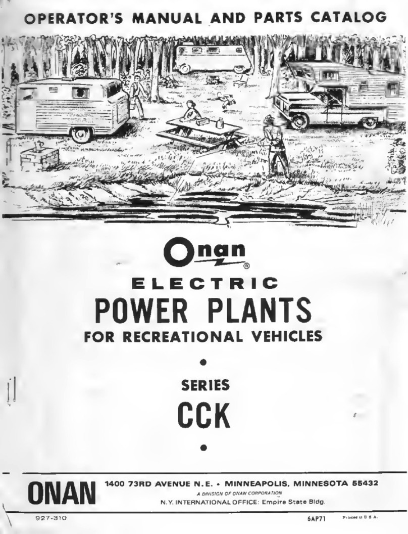
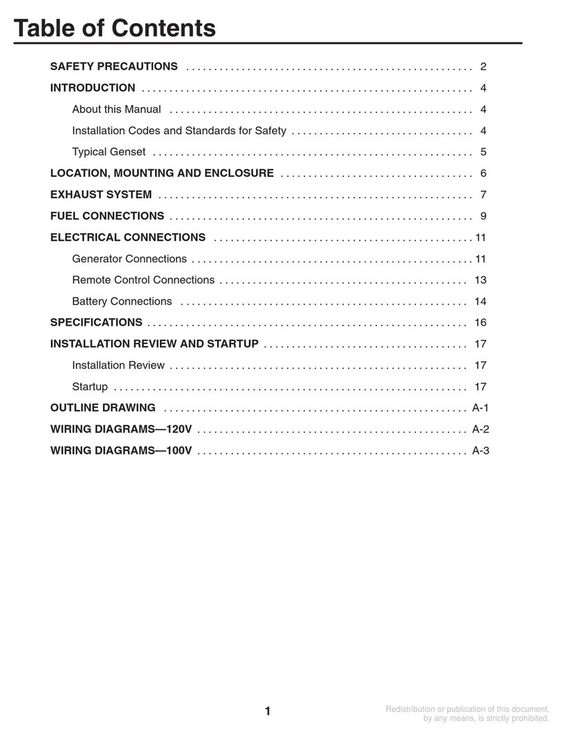
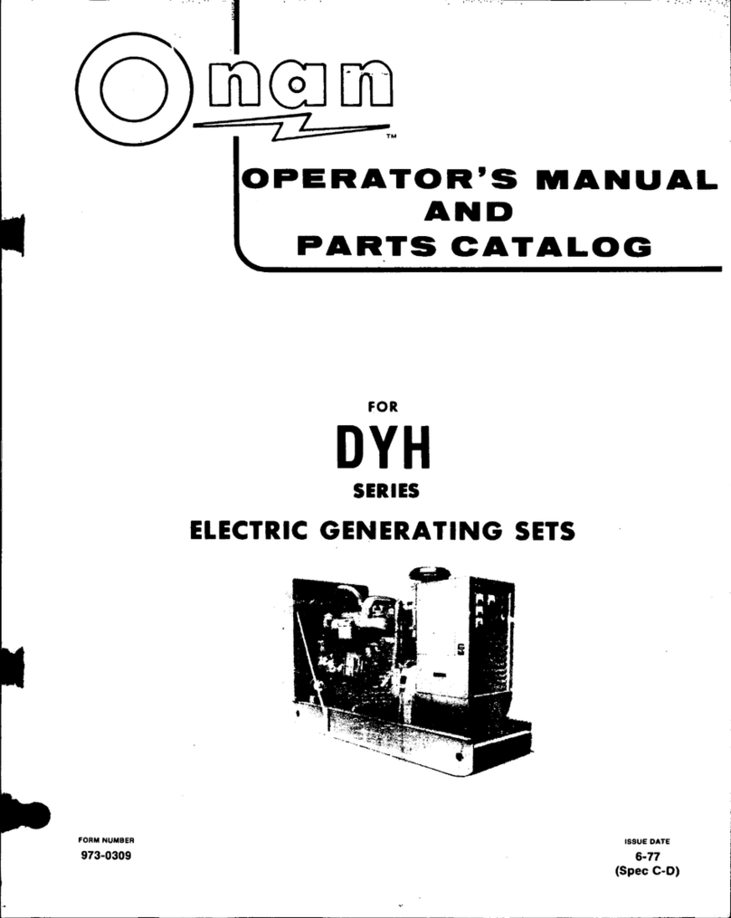
Onan CCK Series User manual


GENERAL
INfORMATION
THE PURPOSE
OF
THIS BOOK.
This
instruction
book
is.furnished
so
that
the
operator
may
learn
of
the
charactertsUcsoftheplant.
.A
thor-
ough study of the
book
wilL help the
operator
to
keeptheplant
in
..
good
operating
condition so
that
it
will give efficient
service.
An
under-
standing of
the
plant
will
also
assist
the
operator
il}
determining
the
cause
of
trouble
if
it
occurs.
KEEP
THIS
BOOK
lIANDY. Such.
simple
mistakes
as
the
use
of
im-
proper
oil,
improper
fuel,
or
the
neglect
of
routine
servicing
mayre-
sult
in
failure
of the
plant
at
a
time
when
it
is
urgently
needed.
It
is
suggested
that
this
book
be
kept
near
the
plant
so
that
it
may
he
refer
...
red
to when
necessary.
' .
SERVICE.
If
trouble
occurs
and
th~operato:t:'
is
unable
to
determine
the
cause
after
a thorough
stuayof
tl1isbook,
or
if
he
is
unable to
deter-
mine
what
repair
parts
are
required,needed
information
will
be
fur-
nished
upon
request.
WHEN
ASKING
FOR INFORMATION,
BESURE
TO
.
STATETHEMODEl,t,.SPEC.,AND SERIAL NUMBERS
OF
THE
PLANT.
THIS INFORMATION
IS
ABSOLUTELY NECESSARY AND
MAYBE
OB-
TAINED FROM THE NAMEPLATE
ON
THE PLANT. .
MANUFACTURER'S
WARRANTY
The Manufacturer warrants each produCt of its manufacture to be
free from·defe.cts
in
materjal and factory workmanship
if
,properly'
installed, serviced and operated under nonnal conditions accord-.
ing
to
the Manufacturers instructions,
Manufacturer's obligation under this warranty
is
limited to
oor~
reeting without charge
at
its factory any part or parts thereof
wllich shan be returned
to
its factory·
or
one
of·
its Authorized
Service Stations, transportation charges prepaid,
within
ninety
(90) days after being
put
into .service
by
theoriglnal user, and
which upon examlnlltioll shall disclose to
the
ManUfacturer's
sat-'
isfaction to have been originally defective. Correction of such
de'-
fect~
by repairto, or supplying of replacements for defective Parts,
shall constitute fulfillment of all obligations
tf)
original user. '
This warranty shall not 'apply to any of
the1.fanufactmer's
prod-
'.
ucts which must be replaced because. of nonnal wear, which have
'.
been mbject to mistlse,
negligenCE)
or acclde:IjJor which shall have
been repaired or altered outside of the !I!anufacturer's factory un-
less autllorlzed by the Manufacturer"
Manufacturer
sh~1J
not
he
liable for
loss,
damage or
e).-pense
directly or indirectly from
the
usc of
it~
product
odrom
any other
cal1se.
The
Manufacturer Inakes
no
"'llrro.ljtY,'~l:>atsoe"er
",.ith re-
spect to componentpartswhich
are
warranted separately by their
respective manufacturers,
..
. .
, .
TIle above warrant)' supersedes
and
is
in lieu of all other war-
rantics, expressed
or
implied, and
no
person,
ag~nt
or dealer is
lluthorized to give all)' warranties.on
hehalfof
tile
~!anufactllrer
nOt
10
nssumefor
the
~I"nllfncttlrer
any' other liability in
COIllI€<?
tion with any
of
Us
pl'oduets Ilnless made
.in
writing and signed .
by
nn
official
of the Manllfacturer.
r~~~~~~~~~~em~~~!~~~~~~1
IMPORTANT
RETT,JRN
WARRANTY ·CAJUJATTACHED TO'UNIT.

• •
••
•
•••
• •
••
• • • • • • • • •
FIGURE
LIST
OF
ILLUSTRATIONS
PAGE NO.
1.
Typical
Installation
.~
;
••.
"
•......
; :
..
n
.8
2. V·entilation
•..............•.................
~
. . . . . . . . . . . . . .. 9
3. Mounting
Base
.
~
.•.•.....•••
~
...
, , .
'.'
;
•..•.•.•.••......
'.
. .
.•
. 10
4. Mounting Cushions •• ,
.............
'
•...
;
......
, '
.....
'
..
" .
.•
10
'5.
Exhaust
Installation.
..
. . . .
..
..
. . .
...
.•
. .
•...
. . . . . . . . . . . . .
..
.
11.
6.
'
Oil
Drain
Extension
.....•......•..........•
,.~~.
.
.•.
. . .
•.
.
...
..11
7.
Dimensional
Outline
for
Manual
Plants
.................
;
..
. .
..
12
8.
Dimensional
Outline
for
Remote
Plants
....•....
; . .
..
. . . • .
..
. • 13
,9.
Dimensional
Outline
for
portable
Plants.
.
..
...
.•
. . . .
.. ..
.
..
. .
14
10.
Battery
Connections -
AC
Remote
Plants
••. • . . •
...
..
.
..
.
•.
.
..
. 15
11.
Battery
Connection,
.Magnet
Service
Plant.
.................
; 15
12.
Start
& Ignition
SWitches,Magnet
Service
Plant
...
:.
..•.
. . . .
•.
16
13.
Load
Wires,
Magnet
Service
Plant
'"
. . . .
...
.
.•.
. . . . •. .
•.
..
. .. 16
14.AC
Load
Wire
Connections..
• . . .
..
. . . . . . . • . .
..
• . . • •. •.
..
. . .• 18
15.
Load
Receptacles
-
Portable
Plants
.................
~
.•
;.
.
..
..
'21
16. '
Plant
Grounding
......
'.'
..................•..............
".
21
17.
Remote
Start~Stop
Stations.
. . . . . ••.
..
•. . . . . . • . . . . . . • . . . . . .
..
22
18.'
Fuel
Reservoir
''Day'' Tank
.....•......•....•....
"
•.....
; " ' 23
19.,
Gas
Hegulator
Connection
...
;
...............•.
:
.........
"
~
25
,20.,
Vacu-FloCooling
.....
;
...•..........•.....•.........•
' '.'
..
•
26
21;
'Crankcase
on.Level
..•.
'"
........
'
.•.
,
........•
"
..
'
.....
','
27,
22.
Governor
Linkage
Lubrication
•.•.....
; :
•...
;
•.•..
;
.....
; . . •
27
23.
Air
Cleaner
Service
.••............
"
..............
,.
; . . . . .
27
24.
Fuel
Shut-Off
Valves;
...........
"
'"
. . . •. . . . . . . . . . . . . . . . . .
27
25.
Priming
the
Fuel
pump"
.••.
',"
. . .
..
. . . . .
•..
•
..
.
..
.
.•
..
. .
..
31
26.
steps
to
Follow in
Starting
the
Plant
....
, •; . •. •. . . . . .
•.
..
. . . 34
27.
Air
Cleaner
Service
...............••.....•.....
" . . . . . •.
..
38
28.
servicing
the
Breaker
Points
•....
'
.•...........
" •. . . . . . .
..
. .
40
29~
Servicing
the
Crankcase
Breather
Valve.
. •. . . . . . . . ••• . . . •.
.•
42
30~
Governor
Adjustments
......................
~
..
" . .
..
...
.•
. 45
31.
speed·Booster
Adjustments.
•. •. .
..
. .
..
. ... . . . . . .
•.
. . . •. . . . . ' 45
32.
Throttle
stop
Lever
Position
.•............•........•
;
•....
; 48
,33.
Oil.Pressure
Relief
Valv-e
Adjustment.
.
•.
.
•.
. •. . . . . . . . . . . .
..
.
49
34.
Carburetor
Adjustments
..•.•...••...
" . .
.•.
. .
..•.
. . . . . . . . . 50
3.5.
>Electric
Choke
Adjustment
;
...........
,
.'
.......
;
...
,.
. •
....
51
36. Magneto
Stator
Installation
.............
"
..........
, .
...
. . . 55
37.
Coil
and
Circuit
for
Magneto
Ignition..
..
. . .
..
. . . . . . . . .
..
. . . •
55
38. Coiha.nd
Circuit
for
Battery
Ignition
.......•.•.
;
..
. . . . . . . . . .
..56
39.-
IgnitionTiming
•.•..
'
.............
"...........................
57
40.
Valve
Service
...•......•...•.
'
........................
" . . . •.
59
41.
Installing
the
Gear
Cover
..
.
..
.
..
. . . . . . . . . . . ••. . . . . . . . .
..
..
60
42.
GovernoJ:' Cup..'
..•...
'.'
...
,
..
;
..•........
','
................
61
0
43.
Timing
Gears
.....
0 ;
•••••••••••••
'
•••••••••••••••••••••
o.
• 62
44;
Fitti~g
piston
Rings
to
the
Cylinder.
. . . .
..
. . . . •. . . •. . •. .
..
. 64
4.5.
RedUCing Connecting Roo
Clearance
•...
. . . .
..
...
.
..
.
..
. .
..•
64
46.
Bearing
Installation.
..
. . . .
...
. .
..
..
. . . . . . . . . . . .
..
..
. •.
..
...
66
47. Oil
seal
Installation.
.
..
.
•.
...
...
. . .
....
. . . . •
..
.
...
. . . . .
...
66
48.
Crankshaft
End-Play.
. . . •.
..
. . . .
•.
. . . . . . . . . • . . . •. . . . . . . .
..
67
49.
Oil
Pump
Removal
.•..•...
,
......•.................
, . . . . . ..
67
50.
Brushes
and
Springs
........
'"
.'
......
, . . .
...
..
...
. . .
•.
.
..
'69 '
51.
"'Commutator
Repair
.•.....
" . . . •. . . . . . .
••
. . . . •. . .
..
•. . . .
..
70
52,
Continuity
Test
Lamp..........................
...........
71
53.'
Armature
Growler
•..•........•..
'
•.....•..•...
'
..•...•..
'
...
71
54.
Generator
Assembly
.........................
;
..
. . •. • • .
..
.
..
73
55.
Servicing
Readi-pull
starter
•..•.•..•.••
"
....•••••....
"0
•
76
'.
•
..
56.
Installing
Readi-pull
starter,
Un1ts"prlor
to
spec.D
!.
,i • "
.~.
'
•...
7'.786.
'.'~".'.'"
57.
n
Installing
Readi-Pull
Starter,
Units beginning spec.'D
•.
.;
•.
••
~
,
'.
..
'.
".
.
~
i

54,>
SUBJECT
TABLE
OF
CONTENTS,
Description
, Introduction
........................
','
................
.
General Description
•.....
,
...
,
.......•....
,
......
, '
..
Engine Details'
............
,
................
, ,
.......
.
Generator
Details,
Controls
.............
,
............
.
Accessories
...........
'
................
'
.....
',
..
,
....
.
Installation
Location,Mobile
Installation
•.•.....
, ,
..............
,
..
Ventilation,
permanent
Mounting
Base
.................
,
Mounting Cushions, Exhaust
..........................•
Oil
Drain
Extension ,
.....
,
...•..
'
...•
,
.......•.......•.
Battery
..............
',
.
~
.............................
.
Start
& Ignition Switches, Magnet Servic,e
Plant
••.•.....•
Connecting the Load
Wires
.....................
,
......
.
Grounding
..•.....
,
..............................
, . "
..
.
Remote Control Switch,
Separate
Fuel
Tank
............
.
Underground Tank,"
''0
ay
" Tarik,
Carrying
Frame,
DOlly
... '
Readi-pull
starter
...
'
..
'
.•.........•.
, .'
................
.
,Gas Regulator
•.........
'
...
;
.......
'
.......
~
.........
~
.
Vacu-Flo Cooling
...............................
'
......•
Preparation
Lubrication ;
•..
'
....•....
'
............................
.
Air
Cleaner
,Fuel,
Before Initial
start
.......•.....•....
Operation
start
ing
the
pIa
nt
•. . . . . . . . . . . . . . •. •. . . . . . . .
..
. . . : . . . . .
Applying the Load
...............
'
......................
'
Charge Rate, Stopping the
Plant,
Changing Fuel
..........
.
Function of the Controls
....................
,
.•..........
Abnormal Operating,Conditions
'Low
Temperatures
..
,
..........
,
....
:
...•
','
...........
.
High,
Temperatures
•.....
". "
....
'
......................
i
...
Dust and
Dirt
....
: . ','
..
'
................
;
......•.......
Periodic
Service
Daily
Service
•...
:
..............
;
......•.
,
..
'
......
,
...
"
Weekly
Service
•................
'
..................•.•
'.
Monthly Service,
.......
,
.........
'
....................
..
Adjustments '
General, Governor and Booster
..•...•.......•
:
.•.••..•
Voltage
Chart;
Speed.
Chart
............
,'
...
,
...........
'
Oil
Pressure
Relief Valve
.......................•....•
Carburetor
.................
;.
"
.....................
.
Electric
Choke
•.....
;
....•
;
........•...
"
....••......•
Maintenance and Repair . ,
General, Table of
Clearances
..•
'"
.........
"
.•.
"
.••.•.
A
ssemblyTorques,
Engine
...........
""
..........••..•
Generator
..................................
~,
......
,"
.
Control
..•
,
..................
"
.....•.
'
......
;
.......
'
..•
Starter
....................•..................•..
'
•....
Service
Diagnosis"
.........
:
.....•....
;'
....
:
...........
~'
Wiring
Diagrams
. ;
......
,.
.,
.'. . . . . . . . .
...........
',"
......
.
PAGE NO.
1
2
4
5
6
7
9
10
11
15
16
16
21
22
23
,24
25
26
28
29
,30
"
31
32
33
,35
36'·'
37
38
39
40,.
43
46
49
50
51
53
69
74
75
79
87
m

ENGINE
SERVICE
CHART
FOR DETAILED SERVICE INSTRUCTIONS, SEE PERIODIC SERVICE.
The
following
recommended
Engine
Servicing
Chart
may
be
used
as
a
guide to
estimating
servicing
requirements
of
ONAN
Gasoline Engines.
.
The
chart
is
based
on
the
Units
operating
under
favorable
conditions,
such
as:
use
of
recommended
fuel and
oils,
etc.
SERVICE &
PARTS.
REQUIRED
Oil
change (Check
daHy).
Clean
and gap
plugs.
____
*A.ir
cleaner.
__________
Ignition pOints. ________
tClean
carbon.
_________
Clean
carburetor.
______
Check
tappets.
_______
_
Grind
valves.
__________
Clean
oil
base.
_______
_
Clean
crankcase
breather
Clean
engine.
________
_
Replace
spark
plugs.
__
Replace
valves,
______
Replace
pOints.
______
.
Replace
piston
rings.
__
*
Check
the
air
cleaner
often~
Thoroughly
clean
and put in
fresh
oil
at
least
every
100
hours.
If
it
is
necessary
to
remove
parts
for
inspection and
gaslmts
are
dis-
turbed
they should
be
replaced
with new ones.,
Periodic
Inspection:
For
loose
or
poor
connections,
fittings,
etc.
t
Recommended
fuel: Use
regular
gradegasoline
of at
least
68
octane
-
. Do not
usepremjurn
type.
If
a high
lead
content
fuel
is
used,
it
will be
necessary
to
remove
t.he
lend
deposits
more
frequently
..
Keep
engine
clean.
IV
HOURS
OF OPERATION
0 0 0 0 0 0 0 0
0 0 0 0 0 0 0 0 0 0 0 0 0 0 0 0 0
0 0 0
~
0 0 0 0 0 0 10
~
(()
0 10 0 10
C\l
(()
10
co
r--
<0
en
(\J
('I) ('I)
""
~
_
_
_
_
_
_
_
JX
IX
IXIXI
~
I
lX
1-.
I--
~~
IXrxIX
t><
IXIXIX
t><
lXIX
rx X
D<
-IX
IXXX
lX
IXZ
-
ex
IX
~
~
IX
IXXlX
-
+--~I--~
..
.tx
LX
IX
~IX
rx]XrxIXIX
IXrxlZ~
--tx
IX
rx
AS
REQUIRED
-
AS
REQUIRED
--
AS
RE~UIR~~
____
--
AS REQUIRED .
0
0
0
It)
l:)
z
....
z
0
t:
0
z
0
U
w
0:
w
f-
w
...J
a.
::E
0
u

DESCRIPTION
1
INTRODUCTION. -This instruction manual
is
supplied to
assist
in the
proper
installation, operation, and
servicing
of
the
CeK
series
electric
generating plants. Unless otherwise stated,
these
instructio~s
apply
to
all
standard plants of the CCK
series.
.
The .plant
model
and specification,
seriaL
number, and
electrical
char-
acteristics
appear
on the nameplate. The
manufacturer
produces
many.
types of generating plants,
industrial
engines,and
separate
generators.
Basic differences such
as
voltage, type ofCQoUng, optional equipment ,
and manufacturing improvements are<i,ncorporated in the model and
speCification
numbers.
Consequently the
MODEL
and SPEC.
NO.
on the
plant nameplate should always
be
mentioned in any
reference
to the plant
if contacting a
dealer
or
the.factory.
Some
details
of these. illstructions may not apply to
special
models hav
..
ing modifications specified
by
the
purchaser.
Due to the wide
variety
()f
uses
for
which
these
plants
are
suitable,
these
instructions
must
be
of a
general
nature.
'I'M
use
of
auxiliary
or
specialequipment,
spectal
installation
requirements,
or
unusual operating conditions may
require
the
operator
of this generating
plantto
modify
these
instructions.
How-
ever,
by using
the.instructions
and recommendations given in
this
man-
ual
as
a
general
guide, it will be possible
to
make
a good installation,
and
to
properly
operate
and
maintain
the
plant.
The
engine end
is
designated
as
the
"Front
End" of the plant.
"Left
Side"
and "Right Side"
of
the
plant
are
determined by viewing
from
the
front end
..
Cylinder number one
(nearer
the timing
gears)
is
on the
"Left
Side" of the
plant.'
.
Instructions apply to both
60
cycle and
50
cycle
alternating
current
plants,
the
main
difference being
in
the
operating speed. Most appliances
can
be
used on
either
500r
60cyde
frequl'!ncycurrentbut
it
is
advisable
to
. check appUances before purchasing
to
assure
that they
are
adaptable
to
the
current
frequency
and"
voltage.

2
DESCRIPTION
GENERAL DESCRIPTION
Each
CCK
generating
plant
is
a complete
electric
power plant,
consisting
•
...
of
an
internal
combustion engine, and a
self
excited
electric
generator
directly
connected
to
the
engine.
Controls
and
accessories
suitable
for
a
normal
installation
and
according
to
the
particular
mOdel
are
supplied.
Each
generating
plant
is
given
an
actual running
test
at
the
factory and
is
carefully
checked under.various
electrical
load conditions
before
·
shipment,
to
assure
that it
is
free
of any
defect
and
that
it
meets
all
performance
requirements.
Inspect the plant
carefully
for
any damage
which may have occured in shipment.
Any
part
so
damaged
must
be
re-
paired
or
replaced
before
putting the plant into
operation.
. .
The
alternating
current
(ac)
plant
generates
current
similar
to
that
supplied by
most
commercial
power
lines.
This
type
plant
must
be
·
operated
whenever
electric
power
is
desired.
The
ac
plant
produces
its
fun
rated
capacity
in
alternating
current
'plus
approximately
135
watts
of
direct
current·
(dc).
Thedc
is
used
as
excitation
current
and,on
electrically
cranked
plants; to
charge
the
starting
batteries.
A
small
auxiliary
load
maybe
taken
from
the
starting
battery
while
the
plant
is
idIe, depending upon
the
charge
condition
oitha
battery.
The
ac
plant
will
not
be
damaged by
operating
it
with no load connected
or
with the.
starting
battery,
on
remote
plants,
disconnected
•.
·
The
direct
cur
I'
Einf
(dc).
plant
is
made in
twobasic.
types:
(1)
for
direct
service
application
asa
power
source
.for lights, power
tools,
etc.;
and
(2)
a
specially
designed
generator
for
lifting magnet
service.
.
.The
dualpurpose
plant
produces
alternating
current,
plus 32 volt de
for
.
battery
charging... When
the
maximum
battery
charging
current
is
in
use,
the
alternatingcurrent
maximum output
is
reduced
to 2250 Watts.
TYPESQFPLANTS.-
The
portable
type
of
plant
is
designed
for
appli-
. . . c.ations
where
portability
is
important.
A
rope-
recoil
starter
serves
for
convenient hand cranking, and
the
plant can
not
be
connected
to
batteries
for
electric
cranking. A
carrying
frame,
a grounding stud and a
pilot
Ught
are
all
desirable
features
of
this
portable
type
plant.
. .
.
.",.
The
.manualtype
of
plant
is
designed
for
applications
where
the
mount-
ing location
is
somewhat
permanent,
either
stationary
or
in a vehicle.
Load
wires
mustbe
connected
djrectly
to
the
output
leads
(except when
an
optional.receptacle
plate
is
added), A
rope-recoil
starter
,serves
for
convenient hand
cranking,and
the
plant can nQtbe connected
to
batteries
for
electric
cranking.
The
remote
control
type
planUs
designed
for
applications
where
the
in-
stallation
will be
more
or
less
permanent.
. When
properly
connected
to
a 12-volt
battery
(or
two
6-voltbatteries
in
series),
tbeplant
may
be
cranlted
electrically
at
the plant,
from
one
or
more
remote
control
1'1,
i ! I \
Ii'.
Ii!
' H
i'l
I
I·
i,
i

switch
location,
or
through
autQmattc
controls.
In
the
event.of
failure
of
the
starting
battery
current,
.the
plant may be
cranked
manually.,
The
remo.te
controitypepla
ll
t
nasa
built:-in
charging
circuit
for
keeping
the
,
startIng
battery
ill:
a
wellcha,rgedcondition.Solderless
terminals,in
the. plant
control.box,serve
fO:r(,!onnectingthe
electrical
load
wires
to
.
the
generator
output
leads.
r··
PORTAt;;:
REMOT}=>.'
5CCK-1
/1A
5CCK-1R/1A
-.-
. *
5CCK-1RV/1A
Magneto
Battery
4
Quart
4
Quart
*
Mounted (4)
CHART
OF
ACPLANT
TYPES.
PLANT·FEATURE
Typical
example:
Ignition: ,
.
Oil
Capacity:
(U. S. Quart)
FuelTank(U.
S. Gallon)
Cranking
and
Choking:
Gasoline
Carburetor:
.Gas-GasQJJI1e
Carburetor:,
Engine RPM
(60
cycle):
EngineRl"M
(50
cycle):
,
Housing;
NOTEt
.*
*
MANUA?,
5CCK~1M/1A
.Magneto
4
Q~rt
*
Separate
(5)
(Mtd. Optional)
Manual
Standard
Optional
1800(nominal)
1500(nominal)
4"
Outlet Box
Optionalt
Optional t
Manual
Standard
Optional
1800(nominal}
1500(nominal)
Receptacles
Standard
Optional
Electric
Standard
Optional
1800(nominal
1500(n.ominal
Terminals
Opt
ionalt
Optional t
Optional
for
Vacu:-Flo

4
DESCRIPTION
ENGINE DETAILS
The
engine
is
a
horizontally
opposed 2
cylinder,
air
cooled, 4
stroke
cy-
cle,
L head
internal
combustion type. Standard
models
burn
gasoline
fuel.. Some
special
models
are
equipped with a combination type
carbure-
tor
for
burning
either
gasoline
or
gas fuel.
The
cylinder
bore
is
3-1/4
inches,
the
piston
stroke
3
inches,
piston
displacement
50 cubic
inches,
compression
ratio
5.
5to
L The
cast
iron
cylinder
and
crankcase
isa
single
casting.
The
engine
speed
is
controlled
by
aflyball
type
governor
built into
the
camshaft
gear.
The
governor
is
externally
adjustable.
The
governor
function
is
supplemented by a
speed
booster.
The
booster
is
operated
by manifold vacuum and
serves
to
improve
stability
under load condi-
tions.
Ignition
current
on
manual
and
portable
type
plants
is
supplied by a high
tension,
flywheel magneto. Ignition
current
on
remote
control
type
plants
is
supplied by
the
starting
battery.
.
The
engine
is
cooled by
air
forced
around
the
cylinder
walls
and head.
Plants
which
are
"pressure
cooled" have
blower
fins
on
the
flywheel
which
draw
air
in
throughthe
opening
at
the
front
of
the
blower
housing.
Special
models
of
the
remote
control
type
plants
may
be
Vacu-FloCooled
and have
blower
fins which expel
heated
air
out through
the
duct
at
the
front
of
the
blower
housing,
as
desirable
for
small
enclosure
installa-
tions.The
letier"V"
appears
in
the
model
ofVacu-Flo
cooled type
plants.
(Example: 5CCK-3RV
/lA).
.
The
engine
has
aluminum alloy 3
ring
pistons,
and full floating type
pis-
ton
pins
..
The
counterbalanced
crankshaft
turns
in two unusually
large
main
bearings
which
are
replaceable-precision-sleeve
type.
The
con-
necting
rods
are
aluminum alloy with
integral
bearing.
Special
models
may
have forged
steel
connecting
rods
and
replaceable
rod
.bearings.
The
exhaust
valves
and
seats
are
Stellite
faced. Valve
tappets
are
ad-
justable
self-locking.
A
positive
rotator
for
each
exhaust
yalve
provides
long
trouble
free
performance
(Rotators
not
on
"Spec A"
models).
The
gear
type
oil
pump supplieS!
pressure
lubrication
to
main
and
con-
nectingrod
bearings.
Oil
pressure
is
controlled
by an
externally-ad-
justable
.spring
loaded
relief
valve.

DEBe
RIP
T
10
N
j"';
I
GEJil"E.RA'I'OR
DETAlLS
. , I . ..
".
.,
I .
·The
alternatingcllrrelJ:tgel}.~rator
..•
isar.eyolytnga¥.~.~~J,lre,self·
exdt
ed, .
inher.ently.reg.41ated.type
•....•.
~h<7AI.1p:E!~el1t
..
q~signp~".tJj~;;~~perator.
with,
saturated,.
4 pole,
...
shuntWO;undf)eld,assureSGJo~~17~g~J~tionof
voltage
b~tween
no
loadalld.f.1.1.1l.·lo~<iconditions;.·····
...
~t?spe~.i.a,Jsertesy;inding.
in
the field of the.remote.star,ting
mode~spermits
the'generatQi:'to be used
!
as
a
starting
motor. .. . .
i
;.-',;':;;
..;:.:(-;'
,
'.
'"
' ":,
",
.
,:'
I"
,:
.' :
"""/,.l.';'·::',···:·'7·:~
..
/.
_ _ _ .
The
armature
isconnecteq
directly.
totl].~".~'ilgine
crapkshaftthr.q"!lgh a
taper
fit
and held
lnplaceiby
a studWl'riii}ipisses through thehollbw
center
of·the
shaft.A.larige.baU.b~ariJ1g
supports the
outer.;endotthe
armature,.
The'.
armaturerfor
the.
ac
.plant contains
bothac
.
and
dc
windings,theac
windinjgscqj).~ecting
to the
collectot
rings, the. de
windings connecting to the commutator.
."
...'
~.
.'.~~~
· " ;
'.
'I'wobasicsizes
of
. ac
generators
prevail
intheCCKseries.The
"
..
smaller
generator
uSeS.
a
4-1/2
inchstack
OfIa.rninations,ratedoutput
is
3500
watts
for
either
60
cycle
or
50
cycle andvoltage.:regulation
is
within plus
or
mlnus3%
of
narneplate;r:atllig.
The.larger
generator,us~s
a
7-1/2
inch
staci{o(laminations,rated
Qutput
is50pOwatts
for60cy-
cle
01"42.50
watts
for
50
cycleandvoltageregulaHoniswithinpluSor
minus
5%
of
nameplate rating. .
..
The
directservice
direct
CI,l.rrent
generator
isa
4 pole,. compOuI1dw()und,
commlltatingpole type
rated
at
5000 watts, 115 volts. ... .
The.magnet servICe generator
is
a4poletypeespectallydes'igKed
for
such
service.
.'I'M
generator·
is
rated
at5000watt.s~Voltage
lsadjust-
ableirom230to
250j
rolts1;>ynieans of the
required
rheostat.
'.
C.ONTROLS
.'
Thenianual
typePlants.h.avea:mariJ~1
choke
on
the
carburetor
and
a stop
button
on
theblowerliollstng.· . . .
·
Thepo!';abletype
plantsha'V~.receptacles.and
aPHb:light
ina~dition
to'
. a manual
chokeana.stopbuu6h>
....
..
The
·~9.rembt.e
tYf>epl~ts.havea~;ele.ctri;.c.~
eonthe
.carbUret()r.,a
start~stop
switc.h,···acharge·~!llm~t.~~Lari.q,~r(.
0.£or
m.anual()relec~
tricstart
10catedonthecontrOlbQx.nl()l1nt~()¥~t'·(the·
gene
r~tor
•..
;
..
'r'he'
..
'
contr()Is
aredesignedS:o
,thatauxiliar.Y'alltQ~:itiQ;;Q~_linetra:nsf~r~qn:-;
tro1.eqllipri'lentinay
be:
cOnnected. .
.....
".
.'
'<.\
.

6
DESCRIPTION
SPECIAL ACCESSORIES
The
following
specIal
accessories
are
not
standard
equipment
but
are
3.-
vailable
at
extra
cost
from
your
dealer.
When
ordering
any of
the
fol-
.
. lowing
special
accessories,
always
be
sure
to give
the
Modetand
Serial
numbers·
of
the
plant
on
the
order.
GASEOUS
FUEL
CONVERSION
~TS.
-
These
kits
contain
parts
and
in-
structions
which
permit
the
use
of Butane,
Propane
or
natural
gas
as
well
as
gasoline;
AUTOMATIC CONTROLS (ACRen:lote
Start
Plants
Only)
....
A
separate
control
is .
available
for
either
50
or
60
cyclea.
c.
units
that
willautomaUcally
start
and
stop
the
plantas
the
load
requires.
LINE TRANSFER CONTROLS
(AG
Remote
Start
Plants
Only).-
Line
transfer
controlsare
available
for
use
with
either
500r
60
cycle
units
instandby
service.
When
regular
power
service
fails,
the
line
transfer
control
aritomaticallystarts>the
standby
plant
and
takes
over
the
load
..
Theplant
stops
automatically
when
regular
service
is
restored.
. ..
. .
UNDERGROUND
FUEL
TANKS
AND
LINES. -
55
gallon and 110 gallon
fuel
tanks
and
5/16
inch
and
3/8
inch
copper
fueLlinesin
either
25
or
50
foot length
are
avail-
able
for
installing
the
fuel tank underground.
REMOTESTART-STOPSWlTCHES
..
-
Additiollairemote
start-stop
switches
are
available
from
your
dealer.
a-CONDUCTOR CABLE.
~
This
#18-wire3-conductor
cable
is
designed
for
remote
start-stop
station
installation
and
.
is
adequate
Size
for
switches
within 250
feet
wire
distance.
TW()..;WHEEL DOLLY. -
The
dolly
makes
the
plant
portable' by one
man.
.
The
dolly
is
designed
to
assemble
to
the
tubu.-
larcarryingframeas
furnished
on
the
portable
type
plant.
Thedolly
has
semi-pneumatic
tires
and
adjustable
folding
handles
with hand
grips
•
..
FUELRESERVOlR(DAY)TANl{.
-
This
tank with fittings
can
be
mounted
. on
the
plant
and
serves
to
assure·
. quick
starting
of
standby
plants
by
replenishing
by
gravity
feed, fuel
lost
from
the
carburetor
during
shut-down
periods.
.
COLD
WEATHER
SHUTTER~
-.
FitsVacu-flo
plants
..
Lirnits
air}Iow.

.feet of
inlet
area
and a
SiIllHa¥\1~mount
for
an
outlet
if
the
plant
is
the
pressure-cooled
type.
':prElY~~~i.recirculanOnolll~,!tted
air
wherever
.' ..
'.
possible_
The
vactium-c,~oled·type;p.1ant
iSl1l()r¢easily.adapted
to
small'
enclosure installation, since h,eatedair call
[)e(;i~C.ted
outside.
....
.
'.- . - "
":-
."";
"':'- ' - - " "
.<:
',,:,'
',-,.
,,\,:'-',
:-
." '
";
.
. .
.EXHAUST GASES FROM INTERNALCOMBPS,;£,
..
,
'ARE,DEAD:LYPOISONQUS.
·.EXCES~lVE~INHA\
.
CA
"USE
SERIOVS'
ILLWESSORI):EATH
•.•...
NEV'
'.
.
'.
'rHEPLANTINSIDE A'BUILDINGOR.
OTHER'
.SPACEWITH()UTPIP:Ii.!OJiLLEbCHAus'tG1\S .
..'
THE
ENCLOS,URE.
. . "
,"
'. .
'..
.
,',
...
'.
,',
.',
LOCATION.
,-TM
pref¢r~bleamb,ien,tait,Jemp~~aturefOrbestengine.'
,.'
..•
.
,",
.performancE!
isweUab9yefree~Wg;.and
theprefe;rable" '
ambie~t
air
temperature
for. mO$tefficteJ:'lt'ge,neratbr
operaUonls
,well
..
under
lOOoF
• and
shouldnotexceedUOoF.if
conditions
permit
con~
·trollingtl}'etemperature.'
. . . .
Iftllegeneratingplant'
ist9,J~¢installed,
in
,~
permanent location,'choose"
a site'{ormQuntin(!t
tile
plant
that
will
be
more
or
less
centrally located .
in;relati'on,tothe
elec~rical
load. 'Plan toaYoici
runningwiringwhich
carries
a heavy e,lectljical,load foralongdisb.U!ce
..
The
greater
Ule
distance,lhe,
larger
t~ewirell1:ust
be>
The
selected
site
should be
in
a.
clean;
dry,.
wellyelltJlated
location,preferably
heated
in
extremely cold
,weather.'
A
dustyor'dan:ip'locationwilln~G¢!ilsitate
more
frequent
ser-
vicing,.
.......
,.,
".'
.",
......
.
..
,.,
......
,
MOBILE
INSTALL:A1;'Io.N~,":,'rhegeneratingplantmust
be
securelybol-
..
.'.....
'
..
'
.'
..ted
to
thefloor
or
other r
igidmember
if
it
,lstobe'mQuntedin,~yehiCle.
'D,ql1otJleglect the piping'of the poisonous
exha~stgases
to
,t~~,911tQQO~s.:KeepJlle,eXh~1l(3tPipWg
Seyer;ll
..
inches
.away
ironj
inf}am,mablemater.ialsMdsupporttlJ.e piping securely so .
tnatU
willrem~inp~~l11l\tneiltlYin,pl~ce.
....
. . .
. ". ..........
.....
.
.C.i'\lJTJON,>:
...
'
........
. .
.'
..•
....
..
'.
Do.
not
run
theveh,icle.J~s;iq.,~aclos.edbuUdingand
operate
the
gellerating
'set
..
'
J:,1e
suretl1;:lt
lhe
eXhau.~t.line~,
are
,carefully.extended to theou.tside
•.•.
ofJhebuilding. . .' . . .
..
·IftbevehiCleisa.~10sedon:~;pr2pet\~~litilatiOnmust
be
proVid~d
..
Sev-
'eral
smallopening13iWill:sufnC~;})ut
therem.ustbe
at
least
3
..
1!2
square>

-
:z.'IG.
1
"7
TYPICAL INSTALLATioN

. .
.
"
_'
, .
__
.
9
INSTA
LLATION
Plahtsl110unted in
vehiclesmdstalso.begrounded
..
Review
the applicable
sections
in
t he
National
Electrical
Code and
local
regulations'
to,.deter;..
mine
the
steps
to
be takenforgrotindi.n.g:the
set,
. .
" "
',~-
'-
, ' -.'
. .
~'
.
.YENTILATION(PIiESSUREJC
GOL
ED,P
LA
NT)
.-Hrovidf;,\,,<lcmpleventi-.
.....
.
....
. la:tion"r:I'P:7re
must
beacol1/>t;int
supplyoffr:esh
air
,forcooHngthe
plant.."
In:.~JJrgeroom,
.
or
outo!
doors,C()olingwiU
be
no.
problem.
Thereshou~d"pe,atleast
two openings,
preferaplyat.opposite
ends
of
theel1cl()s~:re,
to
provide
ampleventHation.'fhe
openings: should be. adj\ll:lta}bJesothat
the
vol~me
of
air
can
pecontrolledfor.cold
weather
operation
..
The
area
of
the
air
inlet snould be
at
least
3-1/2
square
feet. The
area
of
the
air
outlet
should be
at
leasta~.,largeas
that
of
.the
air
inlet..'
FIG. 2-VENTl1.A'!'ION(PRESSURE-COOLED PLANT)
The
installation
of additional openings
maybe.necessary
under
some
conditions
to
prevent
recirculatioriof
heated
air
•.
If
this
becomes.
nec-
essary
•.
airoutJets
in
the
roof
.orin
the wall
near
the ceiling
win
help.
,The
size
of the
air
inlet
.canbe)nc:re~.sed
or
an additional
air
inlet
in-
stalled
nearby.
If
the
unit
is
tobeoperated
wnereflying
Unt,
chaffor
dust
is
likely
to
be
carr
iEidto
thetntake
air:sireal1l'
airJnlet
and outlet openings should
be mad
ewithref
erencetoJ.heprevaHing'
'Wind
...
In.
such
installations
the.
air
inlet
shouldbescreenedan,dthe,
screen
kept cleall
to.
prevent
r"""'.T"II'_
tiortof.airflow.
l?E.RMAN~.NTMOVNTiNG:BASE,
.··.·~.Mo4Pt,the
plantonastibsta,ntia,lly
.
......
.'
.'.
....•.
'..
'.'
,JevelQg~Gr~teo:rtinlberoi
stt,uc-
tural
steel.
base>pref~r~plyat,~e~stl?
,.~nc4~f3high.
··.Locat,e.the.
b~s~
asJo.·px:ovipe.
at
Jeast·
24jllcl1e~:spaCf:)'Ollll,nsides.,
for
conyenieri'ceIn
...
,-,.
,.',',
- .
_."
-i,,:
',',_;
, ._'
-.
_",'
,," .

POS1TlON
MOUN:Tf!llG
BOLTS
IN
CLEATS PLACED ACROSS FORM
..i:;;liiiliJ'il!""'"
fO
INST
A
LLATION
~
..
'-
'
,'.
,~,,;
BOLT
....
~"
",
FIG.
3
-MOUNTINGBASE
support
8
inches
apart~Front
cent~r
to
rear
center
mounting
distance
is
15....;1/8
inches.
Be
.sure
the
mounting
base
is
smooth
and
level
so
as
toav,oidexcessive
strain
on
any
one
of
the
four
mountingfeet.
. .
MOUNTING ClTSmONS. -:1nstaU
the
mounting
cushions
.asillustrated.
.
The
metal
spacer
and
the
fIat
w.asher
at
each
.end,
p:r~vents
excessive.compl'€ssion
of
the
rubber
cushions~
\ -..
EXHAUST.
-Pipe
the
exhaust
gases
outside
the
enclosure,
using 1 inch
pipe
or
larger
..
Increase
the pipe
size
used, one siz.e
for
each
additional
10
feet
.in
distance.
Avoid
sharp
bends
if
possible
by
uSingbentpipe.or
sweeping elbow. where
necessary.
Connect
ihefIex-
ible
exhaust tube
to
thepJant
exhaljstoutlet,
.
Ii
sufficienflengih
of
pipe
to conduct the
ga..s{:!s
outside the enClosure, and
the
mufflertothepipe

11
i 1
ije
T.,6
L L A T I 0 N
'.
Qutstdethe enclosure. Insulate
or
shield the exhaust pipe
if
it
comes
close
to
or
passes
through a !1ammablewall
or
other
material.
If
the
exhaust line must be inclined upward from the plant,
construct
a conden-
sation
trap
of pipe fittings and insta,ll it at the point
wherE;j
the
upward
pitch begins. Drain the
trap
periodically.
.
..
'
If-EXHAUST
j"lE--MUST
:"
p~
PlTCHEe lj,".iWAr2D
,
CONS7RU<:;T
A
,RAP
,
OF
PIPE
FITTINGS
AT
POINT
OF
R?!Sfr
EXHe,l)$T L.IN!': PAS.!iING
CONOtNsATION
THROUGH WA\-L
TRAP
OR
PARTITiON
FIG.
5-
EXHAUST
INSTALLAl'ION
If
exhaust noise from
the
standardrpuffler
will
be
objectionable,' an
un-
dergrounci muffler
ma,y
be
constructed.
Do
not \lSe
an
underground muf-
fler
if
there
is
any danger
of
its
filling with
water
a,tany
time.
Usea
heavy
metal
drum
or.pail
and weld
s~itable
fittings
for
inlet and outlet
pipes.
Do
not
use
a.
container which contained.
any
flammable liquid with-
o\ltfirst
making
sure
that
all
explosive vapors have
been
driven out.
Re-
move the bottom,of the
drum,
or
drill
holes
in
the
bottom, to allow con-'
deU/3ation
from
the
exhaust
gases
to
drain
away.
The
muffler exhaust
pipe
Sho'lj.ld
extend
a,t
least
24 inches
aboveground,
with a gooseneck
fit-
ting
on
the,end
to
prevent
entry
of
rain
or
snow. '
OIL DFtAINEXTENSION. -The addiUon
of
an
oil
drain
e:xl:enSionpipe
. andco\,lpl!ngwill provide for cleanUness and
convenience in draining oil
from
the
oil
base.
Before
fHUng
the oil
base
wjthoil
as.
<:lj.reeted
under
Preparation,
remove
the
dra,in plug from
the
oil
base
and install a
3/8
inch pipe nipple and coupling in
it/3
place.
In-
atall the
drain
plug in
thecoupllng.
Whendl'aining
the
oil, remove only
the
p\ug. .
FlO. (i .. OILDRAIN
lllXTENSION

-~
...
~
~
....
,
·1
~
~
~
(3
~
t-t
o
~
~
~
~
~
!:iJ
'~.
£:
t-<
~
§:
~.
~
[j
i&
.£
M_
i
~ANUAL.
CC
K
SODA
474
FURNISHED WrrH SEPARATE 5
GAL
FUEL
TANK
~
HOSE j ::. FT.
FLEx.
EXHAUST
TUBING
WI
Tt-l
TANK
TYPE
MUFFLER.
INLET
r-
7 l
{AIR
,.
~AUST.
OUTLET
I
PIPE
TAP
f',IR
0UTLET
I
21.L
·'ERMINAL
BOX
1°16 (;;-AR51U:.)
~
~
9 8
--J
i f
\lrFF
~
rfl=1
TI
I
I-
~\
..
OIL
PRESSURE GA.
4MTG
HOLES
.
. FOR
mDIA
BOLTS
~
ON
4QT.,BASE
DRA.lN IS
ON
~
OIL
DRAIN
i PIPE
PLUGS
.
OIL
FILL
MODEL
DIM.
'A'
GEN.
CONN. .
OF'
-IUNAL IL
BASE
l
30.5
CCK
264/8
1<p-2WIRE BASE
CAP.IDIM:'B"IDIM~CIDIM.U'
305CCK
28
1(J)t3<1>-3WIRE
3QUART
\19
'iz I B
'1,6[IS7/161
D.W.ONAN
t
SONS.,INC
5 CCK
29
"VB
1(!J-2 WIRE. 4
QUART
120
')1,;\
9
'14-116
5/
...
I
MINNEAPOLIS,
MINN.
SCCK
31 Y2 1(!J13<!l-3WIRE
'SCCK
:'4-V2
3$-4
WIRE
DWG.
N.2.500A
474-
..
./--
I-'
t.:I
......
Z
00
1-3
>
~
>
~
1-3
....
o
z

"=.i
a
<Xl
o
i
I:i:I
~
.....
o
.!2:
»
t'"
g
~
t::
~l
"=.i
~
.!:tj
pj
5
~
I:i:I
..
r:d
r;
Z
t'Il.
'"'
.oj
....
U')
T
~co
..
I
REMOTE
CCK
SOOA475
THREAD
rs~
li
..
/,UEL
INlET-i
PIPE
\GN.SWITCH
\EX.Hp..tJS1.O
_.U.TL.E.T_
__
/ ..
_._.
IR
..
INLE.T
\H.ARGE
AMMETER
-'\_
.\f.P'PE
TAr·", . 1 .. . .
•••
,
\,\,START
STOP
SWITCH
l=16~
,y -. ..
!~~
\ .
FUEL
INLET
.
-\
-I I
\'
I'
.
-I
I
-
..
~
+:+
1,1
•
......
~=.L.
~------r.
\.
~~~/
k
PIPE
THf).(FAR..SlPE)
• 1.
....
"
11
Il~
.
-,A-J
t---r--r--'
Z
t'Il
t')lv
to,3
o
N
)-
t"'
-I
..,..
t"'
i
)0-
I
~
......
~---~fLf4~~~~~I~~~~
o
z
I
t-6-~
I
:...--.
-12----1
PRESSURE
GA.
\
MTGHOLES
',5.
DRAIN
i PIPE
PLUG
\ FOR
16
DIA
BOLTS
\"OIL
FILL
NOTE:
·!"URNISHE'D
WITH
SEPAR"TE:
M':lOF
305
CCK
305CCK
seCK
seCK
DIM.~A
GEN.
CONN·
26.:y8
1$-2WIRE
28
l(!)t3d>-3W~
297/p.
1$-2
WIRE
31
Y2
1$~3<1>'3WIRE
S
GAL.
I="UEL
TANK
~.
HOSE;
3
FT.
F'LEX.
EXHAUST
TU61l<G
-
D.W.
ONAN
t SONS.,INC-
Y;ITH
TAN
K
TyP
E.
II\UFFLE.R..
MINNEAPOLIS,MINN.
DWG.
NStSOOA41S
....
<:.)

-
~,
~
c;)
I:Q
~
~
c
~
~
t-<
o
t::::::l
I-j
~
~
~
~
'i:I
@
~
&;
~
:t:..
~
tt:5
~"%iiW4l&kig;av
500A473
EXHAUST MUFFLE!=\
ON
.....
1;~W
o
L
C'll~
<\J
4 Q1:,DRAI N
15
ON
,------REA01-PULL
S,"'R,ER
LRECEPTACLE EOX
(yflR. SlOE)
V,ODEL
DIM.:~
GEN.
CONN.
305
CCK
26
¥s
1<j)-2WIRE
305
CCK
28
IQfr3<D-3WIRE.
SCCK
29
"V8
11j)-2WIRE.
seCK
31 1/2
1$~3¢-3IWIRE
seCK
34V2
3dl-4
WIRE
REFERENCE
NOTE.:.
SE.E.
DR."'WING
",2
410C2.35
x
..
OPTIONAL O,L DI"'...-2.C.":>'"
I
~
PORTABLE
CCK
H
Z
00
1-3
>
t-'
t-'
>
1-3
H
o
Z
FOR
DOLLY
D.W.
ONAN
t
SON5,
INC.
MINNEAPOLIS,
MINN.
OWG.
N~
50oA473
Other manuals for CCK Series
2
Table of contents
Other Onan Portable Generator manuals

Onan
Onan NH User manual

Onan
Onan BGE User manual

Onan
Onan 12.0 RDJC Series User manual

Onan
Onan RDJF Series User manual

Onan
Onan Protec Series User manual

Onan
Onan CCK Series User manual

Onan
Onan K5000 User manual

Onan
Onan CCK User manual

Onan
Onan MDJF Series Instruction Manual

Onan
Onan DKHA Series User manual

Onan
Onan MDKBK User manual

Onan
Onan Ensign 4500 User manual

Onan
Onan Emerald Plus BGE Series User manual

Onan
Onan 25.0 DEH-53R Series Instruction Manual

Onan
Onan MJA Series User manual

Onan
Onan EM Series Instruction Manual

Onan
Onan CCKB User manual

Onan
Onan 3.0 AJ User manual

Onan
Onan LK Series Instruction Manual

Onan
Onan JB Series User manual