ARTERY AT32F421 Series User manual

AT32F421 GPIO user guide
2021.11.29 1Rev.2.0.0
www.arterytek.com
AN0069
Application Note
AT32F421 GPIO user guide
Introduction
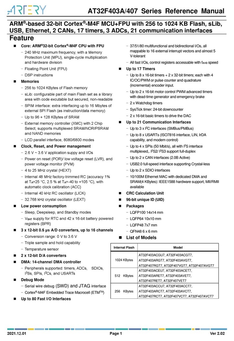
AT32F421xx general-purpose I/Os (GPIOs) provide a wide range of interfaces to achieve digital or
analog communications between MCU and other embedded devices. Besides, AT32F421 series
GPIOs feature rich I/O multiplexed functions to enable multiple peripherals to work at the same
time, and make sure that each pin is connected to only one peripheral at a certain time so as to
avoid conflicts among peripherals.
Reference materials:
AT32F421_Firmware_Library_V2.x.x\project\at_start_f421\examples\gpio
GPIO and IOMUX section in the reference manual of AT32F421
Note: The code in this application note is based on Artery’s V2.x.x BSP (the version of board support
package). When in use, attention should be paid to the differences regarding to the versions of
BSP.
Applicable products:
MCU
AT32F421xx

AT32F421 GPIO user guide
2021.11.29 2Rev.2.0.0
www.arterytek.com
Contents
GPIO features ......................................................................................................... 5
GPIO ........................................................................................................................ 6
GPIO toggle.............................................................................................................. 8
5V-tolerant or 3V-tolerant IO..................................................................................... 8
Standard 3.3V-tolerant pins (TC).................................................................................8
5V-tolerant pin with analog function (FTa)...................................................................8
5V-tolerant pin (FT) ......................................................................................................9
IOMUX ................................................................................................................... 10
I/O multiplexed function input/output ...................................................................... 10
Special I/Os............................................................................................................12
Debug multiplexed function pin .................................................................................12
Oscillator multiplexed function pin.............................................................................12
Backup domain pin ....................................................................................................12
GPIO firmware driver API .................................................................................... 13
Output mode........................................................................................................... 13
Input mode ............................................................................................................. 13
Analog mode ..........................................................................................................14
Multiplexed function mode......................................................................................14
USART I/O multiplexed function mode configuration ...............................................15
TMR I/O multiplexed function mode configuration ....................................................15
I2C I/O multiplexed function mode configuration ......................................................16
Revision history................................................................................................... 17
AT32F421 GPIO user guide
2021.11.29 3Rev.2.0.0
www.arterytek.com
List of tables
Table 1. I/O port bit configuration table................................................................................................7
Table 2. TC pin example ......................................................................................................................8
Table 3. FTa pin example.....................................................................................................................9
Table 4. FT pin example.......................................................................................................................9
Table 5. Configure port A alternate function by GPIOA_AFR register...............................................10
Table 6. Configure port B alternate function by GPIOB_AFR register .............................................. 11
Table 7. Configure port F alternate function by GPIOF_AFR register...............................................11
Table 8. Document revision history....................................................................................................17

AT32F421 GPIO user guide
2021.11.29 4Rev.2.0.0
www.arterytek.com
List of figures
Figure 1. Basic structure of I/O port bit................................................................................................6
Figure 2. I/O toggle speed ...................................................................................................................8

AT32F421 GPIO user guide
2021.11.29 5Rev.2.0.0
www.arterytek.com
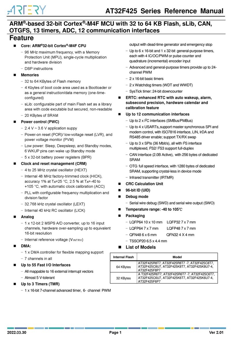
GPIO features
48-pin package (largest) has 39 multi-function bidirectional I/O ports
All I/O ports can be mapped to 16 external interrupt vectors
Almost all I/O ports are 5V tolerant (except for 4x OSC/OSC32 pins)
All fast IIOs, control registers accessible with fAHB speed
The peripheral function of the I/O pin can be locked through a specific operation to avoid
unwanted writing to I/O registers
Each GPIO pin can be individually configured by software as output (push-pull or open-drain),
input (with or without pull-up or pull-down) or a multiplexed function peripheral port
Optional current sourcing/sinking strength
Port bit set/clear register (GPIOx_BSRE) and port bit clear register (GPIOx_BRE) provide bit
access ability for the GPIOx_OPTDT register

AT32F421 GPIO user guide
2021.11.29 6Rev.2.0.0
www.arterytek.com
GPIO
During and just after reset, the multiplexed functions of GPIOs are not active, and most I/O ports
are configured in input floating mode.
When configured as output, the value written to the output data register (GPIOx_OPTDT) is output
on the I/O pin. It is possible to use the output driver in push-pull mode or open-drain mode (only low
level is activated while the high level shows high impedance)
The input data register (GPIOx_IPTDT) captures the data present on the I/O pin at every AHB clock
cycle.
All GPIO pins have an internal weak pull-up and weak pull-down, which can be activated or not,
depending on the value of the GPIOx_PUPDR register.
Figure 1. Basic structure of GPIO
IO
ESD
protect
SMT trigger
PU
PD
output data
output enable
input enable
input data
push/pull
strength control
analog input/output
AHB bus
GPIO controller
Single IO
Analog
module

AT32F421 GPIO user guide
2021.11.29 7Rev.2.0.0
www.arterytek.com
Table 1. I/O port bit configuration table
CFGR[1:0]
OMODE
ODRVR[1:0]
PULL[1:0]
I/O configuration
01
0
ODRV[1:0]
0
0
GP output
PP
0
0
1
GP output
PP
0
1
0
GP output
PP
0
1
1
Reserved
1
0
0
GP output
OD
1
0
1
GP output
OD
1
1
0
GP output
OD
1
1
1
Reserved (GP output OD)
10
0
0
0
AF output
PP
0
0
1
AF output
PP
0
1
0
AF output
PP
0
1
1
Reserved
1
0
0
AF output
OD
1
0
1
AF output
OD
1
1
0
AF output
OD
1
1
1
Reserved
00
x
x
x
0
0
Input
Floating
x
x
x
0
1
Input
PU
x
x
x
1
0
Input
PD
x
x
x
1
1
Reserved (floating input)
11
x
x
x
0
0
Input/output
Analog
x
x
x
0
1
Reserved
x
x
x
1
0
x
x
x
1
1

AT32F421 GPIO user guide
2021.11.29 8Rev.2.0.0
www.arterytek.com
GPIO toggle
All I/O ports of AT32F421 series are fast I/Os with control registers accessible at fAHB speed so that
the GPIO toggle frequency can reach 60 MHz with ease.
Figure 2. I/O toggle speed
5V-tolerant or 3V-tolerant IO
Standard 3.3V-tolerant pins (TC)
All oscillators use standard 3.3V-tolerant pins.
PC14/PC15 (OSC32_IN/ OUT)
PF0/PF1 (OSC_IN/ OUT)
Table 2. TC pin example
Pin name
Pin name
IO structure
Multiplexed function
Additional function
PF0/OSC_IN(PF0)
I/O
TC
I2C1_SDA
OSC_IN
5V-tolerant pin with analog function (FTa)
The ports occupied by comparator input pins and ADC are 5V-tolerant pins with analog function.
PA0 –PA7
PB0 –PB2, PB12 –PB15
When configured as input floating, input pull-up or input pull-down, FTa pins are 5V tolerant;
when configured in analog mode, they are not 5V-tolerant, and input level must be less than
VDD + 0.3V at this time.

AT32F421 GPIO user guide
2021.11.29 9Rev.2.0.0
www.arterytek.com
Table 3. FTa pin example
Pin name
Pin name
IO structure
Multiplexed function
Additional function
PA0
I/O
FTa
TMR1_ETR /
USART2_CTS
/I2C2_SCL /
COMP_OUT
ADC_IN0COMP_INP2
/ COMP_INM6 /
WKUP1
5V-tolerant pin (FT)
Other GPIOs are all 5V tolerant.
Table 4. FT pin example
Pin name
Pin name
IO structure
Multiplexed function
Additiona
l function
PA8
I/O
FT
TMR1_CH1 / USART1_CK /
UART2_TX / I2C2_SCL /
CLKOUT / EVENTOUT
-

AT32F421 GPIO user guide
2021.11.29 10 Rev.2.0.0
www.arterytek.com
IOMUX
I/O multiplexed function input/output
Most peripherals share the same GPIO pin (For example, PA0 can be used as TMR1_ETR /
USART2_CTS /I2C2_SCL / COMP_OUT)
A GPIO pin is connected to only one peripheral at any time.
Some peripheral functions can also be remapped to other pins so as to get more peripherals
that can be used at the same time
Selecting one of the active multiplexed functions on each port line is determined by GPIOx_MUXL
or GPIOx_MUXH multiplexed function register. The user can use these two registers to connect
multiplexed function module to other pins according to the application requirements.
Table 5. Configure port A multiplexed function by GPIOA_MUX register
Pin
name
MUX0
MUX1
MUX2
MUX3
MUX4
MUX5
MUX6
MUX7
PA0
USART2_CTS
I2C2_SCL
TMR1_ETR
COMP_OUT
PA1
EVENTOUT
USART2_RTS
I2C2_SDA
TMR15_CH1
N
PA2
TMR15_CH1
USART2_TX
PA3
TMR15_CH2
USART2_RX
I2S2_MCLK
PA4
SPI1_NSS/I2S1_
WS
USART2_CK
TMR14_CH1
PA5
SPI1_SCK/I2S1_
CK
PA6
SPI1_MISO/I2S1
_MCLK
TMR3_CH1
TMR1_BKIN
I2S2_MCLK
TMR16_CH1
EVENTOUT
COMP_OUT
PA7
SPI1_MOSI/I2S1
_SD
TMR3_CH2
TMR1_CH1N
TMR14_CH1
TMR17_CH1
EVENTOUT
PA8
CLKOUT
USART1_CK
TMR1_CH1
EVENTOUT
USART2_TX
I2C2_SCL
PA9
TMR15_BKIN
USART1_TX
TMR1_CH2
I2C1_SCL
CLKOUT
I2C2_SMBA
PA10
TMR17_BKIN
USART1_RX
TMR1_CH3
I2C1_SDA
PA11
EVENTOUT
USART1_CTS
TMR1_CH4
I2C1_SMBA
I2C2_SCL
COMP_OUT
PA12
EVENTOUT
USART1_RTS
TMR1_ETR
I2C2_SDA
PA13
SWDIO
IR_OUT
SPI2_MISO/I
2S2_MCLK
PA14
SWCLK
USART2_TX
SPI2_MOSI/I
2S2_SD
PA15
SPI1_NSS/I2S1_
WS
USART2_RX
EVENTOUT
SPI2_NSS/I
2S2_WS

AT32F421 GPIO user guide
2021.11.29 11 Rev.2.0.0
www.arterytek.com
Table 6. Configure port B multiplexed function by GPIOB_MUX register
Pin
name
MUX0
MUX1
MUX2
MUX3
MUX4
MUX5
MUX6
MUX7
PB0
EVENTOUT
TMR3_CH3
TMR1_CH2N
USART2_R
X
I2S1_MCLK
PB1
TMR14_CH1
TMR3_CH4
TMR1_CH3N
SPI2_SCK/I2S2_
CK
PB2
TMR3_ETR
PB3
SPI1_SCK/I2S1_
CK
EVENTOUT
SPI2_SCK/I2S2_
CK
PB4
SPI1_MISO/I2S1
_MCLK
TMR3_CH1
EVENTOUT
TMR17_B
KIN
SPI2_MISO/I2S2
_MCLK
I2C2_SDA
PB5
SPI1_MOSI/I2S1
_SD
TMR3_CH2
TMR16_BKIN
I2C1_SMBA
SPI2_MOSI/I2S2
_SD
PB6
USART1_TX
I2C1_SCL
TMR16_CH1N
I2S1_MCLK
PB7
USART1_RX
I2C1_SDA
TMR17_CH1N
PB8
I2C1_SCL
TMR16_CH1
PB9
IR_OUT
I2C1_SDA
TMR17_CH1
EVENTOUT
I2S1_MCL
K
SPI2_NSS/I2S2
_WS
PB10
I2C2_SCL
SPI2_SCK/I2S2
_CK
PB11
EVENTOUT
I2C2_SDA
PB12
SPI2_NSS/I2S2_
WS
EVENTOUT
TMR1_BKIN
TMR15_B
KIN
I2C2_SMBA
PB13
SPI2_SCK/I2S2_
CK
-
TMR1_CH1N
I2C2_SCL
PB14
SPI2_MISO/I2S2
_MCLK
TMR15_CH1
TMR1_CH2N
I2C2_SDA
PB15
SPI2_MOSI/I2S2
_SD
TMR15_CH2
TMR1_CH3N
TMR15_CH1
N
Table 7. Configure port F multiplexed function by GPIOF_MUX register
Pin
name
MUX0
MUX1
MUX2
MUX3
MUX4
MUX5
MUX6
MUX7
PF0
I2C1_SDA
PF1
I2C1_SCL
PF6
I2C2_SCL
PF7
I2C2_SDA

AT32F421 GPIO user guide
2021.11.29 12 Rev.2.0.0
www.arterytek.com
Special I/Os
Debug multiplexed function pin
They are in multiplexed function mode during reset and after reset, instead of being in input
floating mode like other GPIOs
PA13: SWDIO, multiplexed function pull-up
PA14: SWCLK, multiplexed function pull-down
Oscillator multiplexed function pin
When the oscillator is OFF (default state after reset), related pins can be used as GPIO
When the oscillator is enabled, the GPIO configuration of the related pins is invalid
When the oscillator is in bypass mode (use external clock source), OSC_IN/OSC32_IN acts as
an oscillator clock input pin, and OSC_OUT/OSC32_OUT can be used as GPIO.
Backup domain pin
When 1.2V domain is powered off (when the device enters standby mode), PC13/PC14/PC15
lost their GPIO functions. In this case, if GPIO is not configured by RTC as bypass, these pins
are set in analog input mode.
The following contents are not available in AT32F421 series:
Analog switch (power switch) can only allow a small amount of current (3mA), so in output
mode, there are some limits on using I/O functions of PC13/PC14/PC15: they can only work in
a moderate current sourcing/sinking strength mode, with a maximum of 30pF load, and these
I/Os must not be used as current source (such as driving LED)

AT32F421 GPIO user guide
2021.11.29 13 Rev.2.0.0
www.arterytek.com
GPIO firmware driver API
Artery’s firmware driver contains a series of firmware functions to manage the following GPIO
functions:
Initialization configuration
Read input ports or certain input pin
Read output ports or certain output pin
Set or clear the output on a certain pin
lock pins
Pin multiplexed function configuration
For AT32F421xx series, the driver used by GPIO is at32f4xx_gpio_ex.c/.h, located in the following
directory:
AT32F4xx_StdPeriph_Lib_Vx.x.x\Libraries\AT32F4xx_StdPeriph_Driver
Note: The AT32F421 series GPIOs use different driver
at32f4xx_gpio.c/.h from that of other series. The user
should be noted about this when using.
Output mode
GPIO provides two different types of output modes: push-pull and open-drain. Refer to the following
configuration example of output mode.
GPIO_InitStructure.GPIO_Pins = GPIO_Pins_x;
GPIO_InitStructure.GPIO_Mode = GPIO_Mode_OUT;
GPIO_InitStructure.GPIO_OutType = GPIO_OutType_PP; /* push-pull or open-drain */
GPIO_InitStructure.GPIO_Pull = GPIO_Pull_NOPULL; /* None, pull-down or pull-up*/
GPIO_InitStructure.GPIO_MaxSpeed = GPIO_MaxSpeed_50MHz;/* 10,2 or 50MHz */
GPIO_Init(GPIOy, &GPIO_InitStructure);
Input mode
GPIO provides three different types of input modes: input floating, input pull-down and input pull-
down. Refer to the following configuration example of input mode.
GPIO_InitStructure.GPIO_Pins = GPIO_Pins_x;
GPIO_InitStructure.GPIO_Mode = GPIO_Mode_IN;
GPIO_InitStructure.GPIO_Pull = GPIO_Pull_NOPULL; /* None, pull-up or pull-down*/
GPIO_InitStructure.GPIO_MaxSpeed = GPIO_MaxSpeed_50MHz;/* 10, 2 or 50MHz */
GPIO_Init(GPIOy, &GPIO_InitStructure);

AT32F421 GPIO user guide
2021.11.29 14 Rev.2.0.0
www.arterytek.com
Analog mode
When the user needs to use ADC or COMP channel as input, it is necessary to configure the
corresponding pins as analog mode. Refer to the following configuration example of analog mode.
GPIO_InitStructure.GPIO_Pins = GPIO_Pins_x;
GPIO_InitStructure.GPIO_Mode = GPIO_Mode_AN;
GPIO_InitStructure.GPIO_Pull = GPIO_Pull_NOPULL; /* None, pull-up or pull-down */
GPIO_Init(GPIOy, &GPIO_InitStructure);
Multiplexed function mode
1. Regardless of the peripheral mode used, the I/O must be configured as multiplexed function so
that the system can use I/O correctly (input or output)
2. The I/O pin is connected to the corresponding peripheral through a multiplexer, which allows
only one peripheral’s multiplexed function to be connected to the I/O pin at a time in order to
avoid conflicts among peripherals that share the same I/O pin. Each I/O pin has a multiplexer
featuring 16-channel multiplexed function input/output (MUX0 to MUX15) configured by the
gpio_pin_mux_config() function.
—After reset, all I/Os are connected to the system multiplexed function 0 (MUX0).
—Configure MUX1 to MUX7 to map peripherals’ multiplexed functions
3. In addition to these flexible I/O multiplexed function structures, each peripheral can also be
mapped to other different I/O pins. The number of peripheral I/O functions for different
packages can be optimized. For example, USART2_TX can be mapped to PA2 or PA14 pin.
4. Configuration procedure
—Use the gpio_pin_mux_config() function to connect the pin to the desired peripheral
multiplexed function (MUX), for example, configure PA0 as TMR1_ETR input
gpio_pin_mux_config(GPIOA, GPIO_PINS_SOURCE0, GPIO_MUX_4);
—Use the GPIO_Init() function to configure I/O pins:
- Use the following method to configure the desired pin in multiplexed function mode
gpio_init_struct.gpio_mode = GPIO_MODE_MUX;
- Use the following pins to select type, pull-up, pull-down and output speed.
GPIO_Pull, GPIO_OutType and GPIO_MaxSpeed.
The subsequent sections provide common configuration examples of several peripherals
according to the above-mentioned procedures.

AT32F421 GPIO user guide
2021.11.29 15 Rev.2.0.0
www.arterytek.com
USART I/O multiplexed function mode configuration
/* Enable GPIOA clock */
crm_periph_clock_enable(CRM_GPIOA_PERIPH_CLOCK, TRUE);
/* Connect PA9 to USART1_Tx */
gpio_pin_mux_config(GPIOA, GPIO_PINS_SOURCE9, GPIO_MUX_1);
/* Connect PA10 to USART1_Rx */
gpio_pin_mux_config(GPIOA, GPIO_PINS_SOURCE10, GPIO_MUX_1);
/* Configure USART1_Tx and USART1_Rx as multiplexed function*/
gpio_init_struct.gpio_pins = GPIO_PINS_9 | GPIO_PINS_10;
gpio_init_struct.gpio_mode = GPIO_MODE_MUX;
gpio_init_struct.gpio_pull = GPIO_PULL_NONE;
gpio_init_struct.gpio_out_type = GPIO_OUTPUT_PUSH_PULL;
gpio_init_struct.gpio_drive_strength = GPIO_DRIVE_STRENGTH_STRONGER;
gpio_init(GPIOA, &gpio_init_struct);
TMR I/O multiplexed function mode configuration
/* Enble GPIOA clock */
crm_periph_clock_enable(CRM_GPIOA_PERIPH_CLOCK, TRUE);
/* Connect PA6 to TMR1_BRK */
gpio_pin_mux_config(GPIOA, GPIO_PINS_SOURCE6, GPIO_MUX_2);
/* Connect PA8 to TMR1_CH1 */
gpio_pin_mux_config(GPIOA, GPIO_PINS_SOURCE8, GPIO_MUX_2);
/* Connect PA12 to TMR1_EXT */
gpio_pin_mux_config(GPIOA, GPIO_PINS_SOURCE12, GPIO_MUX_2);
/* Configure TMR1 pins(PA6/PA8/PA12) as multiplexed function */
gpio_init_struct.gpio_pins = GPIO_PINS_6 | GPIO_PINS_8 | GPIO_PINS_12;
gpio_init_struct.gpio_mode = GPIO_MODE_MUX;
gpio_init_struct.gpio_pull = GPIO_PULL_NONE;
gpio_init_struct.gpio_out_type = GPIO_OUTPUT_PUSH_PULL;
gpio_init_struct.gpio_drive_strength = GPIO_DRIVE_STRENGTH_STRONGER;
gpio_init(GPIOA, &gpio_init_struct);

AT32F421 GPIO user guide
2021.11.29 16 Rev.2.0.0
www.arterytek.com
I2C I/O multiplexed function mode configuration
/* Enable GPIOB clock */
crm_periph_clock_enable(CRM_GPIOB_PERIPH_CLOCK, TRUE);
/* Connect PB6 to I2C1_SCL */
gpio_pin_mux_config(GPIOB, GPIO_PINS_SOURCE6, GPIO_MUX_1);
/* Connect PB7 to I2C1_SDA */
gpio_pin_mux_config(GPIOB, GPIO_PINS_SOURCE7, GPIO_MUX_1);
/* Configure I2C1_SCL and I2C1_SDA as multiplexed function. Note that I2C
pin output mode should be as open-drain output */
gpio_init_struct.gpio_pins = GPIO_PINS_6 | GPIO_PINS_7;
gpio_init_struct.gpio_mode = GPIO_MODE_MUX;
gpio_init_struct.gpio_pull = GPIO_PULL_NONE;
gpio_init_struct.gpio_out_type = GPIO_OUTPUT_OPEN_DRAIN;
gpio_init_struct.gpio_drive_strength = GPIO_DRIVE_STRENGTH_STRONGER;
gpio_init(GPIOB, &gpio_init_struct);

AT32F421 GPIO user guide
2021.11.29 18 Rev.2.0.0
www.arterytek.com
IMPORTANT NOTICE – PLEASE READ CAREFULLY
Purchasers are solely responsible for the selection and use of ARTERY’s products and services, and ARTERY assumes no liability whatsoever relating to the
choice, selection or use of the ARTERY products and services described herein.
No license, express or implied, to any intellectual property rights is granted under this document. If any part of this document deals with any third party
products or services, it shall not be deemed a license grant by ARTERY for the use of such third party products or services, or any intellectual property
contained therein, or considered as a warranty regarding the use in any manner whatsoever of such third party products or services or any intellectual
property contained therein.
Unless otherwise specified in ARTERY’s terms and conditions of sale, ARTERY provides no warranties, express or implied, regarding the use and/or sale of
ARTERY products, including but not limited to any implied warranties of merchantability, fitness for a particular purpose (and their equivalents under the
laws of any jurisdiction), or infringement of any patent, copyright or other intellectual property right.
Purchasers hereby agrees that ARTERY’s products are not designed or authorized for use in: (A) any application with special requirements of safety such
as life support and active implantable device, or system with functional safety requirements; (B) any air craft application; (C) any automotive application
or environment; (D) any space application or environment, and/or (E) any weapon application. Purchasers’ unauthorized use of them in the
aforementioned applications, even if with a written notice, is solely at purchasers’ risk, and is solely responsible for meeting all legal and regulatory
requirement in such use.
Resale of ARTERY products with provisions different from the statements and/or technical features stated in this document shall immediately void any
warranty grant by ARTERY for ARTERY products or services described herein and shall not create or expand in any manner whatsoever, any liability of
ARTERY.
© 2022 Artery Technology -All rights reserved
Other manuals for AT32F421 Series
3
Table of contents
Other ARTERY Computer Hardware manuals

ARTERY
ARTERY AT32A403A Series User manual

ARTERY
ARTERY AT32F425 Series User manual

ARTERY
ARTERY AT32F402 Series User manual

ARTERY
ARTERY AT32F413 Series User manual

ARTERY
ARTERY AT32F435ZDT7 User manual

ARTERY
ARTERY AT32F421 Series User manual

ARTERY
ARTERY AT32F425 Series User manual

ARTERY
ARTERY AT32F Series User manual

ARTERY
ARTERY AT32F403A Series User manual

ARTERY
ARTERY AT32F403A Series User manual