OneAccess ONE100 User manual

http://www.oneaccess-net.com
ONE100
Installation Manual September 2008

ONE100 - Installation Manual
2
OneAccess
28 rue de la Redoute
92260 Fontenay aux Roses
France
The law of 11 March 1957, paragraphs 2 and 3 of article 41, only authorizes, firstly,
’copies and reproductions strictly reserved for use by copyists and not for general
use and, secondly, analyses and short quotations for the purpose of example and
illustration. Therefore, ’any representation or reproduction, entire or partial, made
without the consent of the author or his representatives is illegal’ (paragraph 1 of
article 40).
Any such representation or reproduction, made in any manner whatsoever, would
therefore constitute an infringement of the law as sanctioned by articles 425 and in
accordance with the penal code.
Information contained in this document is subject to change without prior notice and
does not constitute any form of obligation on the part of OneAccess.
OneAccess and the distributors can in no case be held responsible for direct or
indirect damage of any kind incurred as a result of any error in the software or
guide.
Every care has been taken to ensure the exactitude of information in this manual. If
however you discover an error, please contact OneAccess After Sales Service
division.
July 2007 Issue
1100 00 T 4023102 T 00 ind. A

ONE100 - Installation Manual
3
How to Read this Manual
The present document is broken down into 7 chapters.
Chapter 1 – Safety Instructions
This chapter provides the safety instructions for use and installation of the router.
Chapter 2 – Directives and Standards
This chapter details the list of standards, which the device complies with.
Chapter 3 – Router Description
This section describes the router front and rear panels and the associated technical
characteristics.
Chapter 4 – Interface Description
This section describes the router interfaces.
Chapter 5 – Technical Characteristics
This section describes technical characteristics such as operating conditions.
Chapter 6 - Installation
This chapter describes how to modify the jumper positions and gives instructions to
connect the router.
Chapter 7 – Power-up
This chapter describes the device power-up and how to monitor the self-test
progress.
Appendix – Connection description
These chapters provide the pin-out of cables that are compatible with the router.

ONE100 - Installation Manual
4
Table of Contents
How to Read this Manual ........................................................................................................................3
Table of Contents ....................................................................................................................................4
1Safety Instructions ........................................................................................................................5
1.1 Connection to Power Supply...................................................................................................5
1.2 Overcurrent Protection ............................................................................................................5
1.3 WiFi .........................................................................................................................................6
1.4 Safety Level Interface..............................................................................................................7
2Directives and Standards..............................................................................................................9
2.1 Declaration of Conformity........................................................................................................9
2.2 Standards..............................................................................................................................10
2.3 FCC Statement (USA)...........................................................................................................11
3Router Description......................................................................................................................12
3.1 Hardware Description............................................................................................................12
3.2 Front Panel............................................................................................................................13
3.3 Rear Panel ............................................................................................................................15
3.4 Motherboard..........................................................................................................................21
3.5 Configuration Identification....................................................................................................22
4Interface Description...................................................................................................................23
4.1 LAN 10/100 Mbps Interface (ETHERNET)............................................................................23
4.2 Console port (CONSOLE).....................................................................................................24
4.3 ADSL - ADSL 2/2 + - RE-ADSL Interface (ADSL).................................................................25
4.4 Ethernet Switch Interface (SWITCH).....................................................................................26
4.5 PSTN Modem Interface (PSTN)............................................................................................27
4.6 RS 232 Interface (V.28).........................................................................................................28
4.7 FXS Analog Interface............................................................................................................30
4.8 FXO Analog Interface............................................................................................................31
4.9 S0/T0 interface......................................................................................................................32
5Technical Characteristics............................................................................................................36
5.1 Climatic Environment ............................................................................................................36
5.2 Power Supply ........................................................................................................................36
5.3 Dimensions............................................................................................................................36
6Installation...................................................................................................................................37
6.1 Opening the Chassis.............................................................................................................37
6.2 Install the WLAN antenna......................................................................................................37
6.3 Wall Mounting........................................................................................................................38
6.4 Connections ..........................................................................................................................39
7Power up.....................................................................................................................................40
Appendix A - Console Cable .................................................................................................................41
Appendix B - RS 232 Interface Cable....................................................................................................42

ONE100 - Installation Manual
5
1 Safety Instructions
The following symbol instructs the user to read the manual carefully before any
connection:
1.1 Connection to Power Supply
To connect the power supply, always follow these steps:
•Connect the DC input jack from the power supply to the DC 12V power input
on the rear panel of the router,
•Connect the power supply to an AC electrical outlet (200-240 VAC). Plugging
in the power supply turns on the router.
Unplug the AC input before assembling/disassembling any part on the
device. The AC input is the part you must disconnect first. For safety rea-
sons, you shall be able to easily access this part.
1.2 Overcurrent Protection
The product requires that the building’s electrical installation is designed for
protection against short-circuit (over current) protection.
A fuse or circuit breaker no larger than 240 VAC, 10A must be used on the phase
conductors.

ONE100 - Installation Manual
6
1.3 WiFi
1.3.1 National restrictions
Country Restriction Reason/Remark
Bulgaria General authorization required for
outdoor use and public service.
France Outdoor use limited to 10 mW e.i.r.p.
within the band 2454-2483.5 MHz Military Radiolocation use. Refarming of
the 2,4 GHz band has been ongoing in
recent years to allow current relaxed
regulation. Full implementation planned
2012.
Italy If used outside of own premises, general
authorization is required.
Luxembourg None General authorization required for
network and service supply (not for
spectrum)
Norway Implemented This subsection does not apply for the
geographical area within a radius of
20km from the centre of Ny-Alesund
Russian Federation Only for indoor applications
1.3.2 Geographical restrictions
For sefaty reason the userhas to keep his distance to 20 cm from the
antenna.
1.3.3 Physical restrictions
The user cannot modify any part of the equipment and the antenna.

ONE100 - Installation Manual
7
1.4 Safety Level Interface
The daughter board must be installed only in the products authorized by
OneAccess and only by qualified personnel as recommended in the
installation manual.
1.4.1 LAN Interface 10/100 Mbps (ETHERNET and/or SWITCH)
Interface marking on the router back panel: ETHERNET and SWITCH
The Ethernet 10/100 Mbps auto-sense has a ’SELV’ (Safety Extra Low Voltage)
interface.
They must be used only for indoor applications, connected to a 10/100 Mbps
interface, which has also the ’SELV’ characteristics.
1.4.2 ADSL, ADSL 2/2+, RE-ADSL (ADSL)
Interface marking on the router back panel: ADSL
The router has an ADSL interface TNV-3 type (Telephone Network Voltage),
designed for connection to a telephone line.
1.4.3 PSTN Modem Interface (PSTN)
Interface marking on the router back panel: PSTN
The analog MODEM interface V.32 (bis)/V.34/V.90/V.92 is ’TNV-3’. It must be
connected to a standard telephone line.
1.4.4 RS 232 Interface (V.28)
Interface marking on the router back panel: V.28
The interface is SELV. It must be used only for indoor applications and connected to
RS 232 interfaces, which are also designed as ’SELV’.
1.4.5 FXS Interface (FXS)
Interface marking on the router back panel: FXS
The FXS modules offer up to 8 FXS accesses (RJ45 connectors). These Interfaces
are ’TNV 2’ (Telephone Network Voltage).
1.4.6 FXO Interface (FXO)
Interface marking on the router back panel: FXO

ONE100 - Installation Manual
8
The FXO interface is TNV-3.
1.4.7 T0/S0 interface (ISDN BRI)
Interface marking on the router back panel: ISDN BRI
These BRI interfaces are TNV-1. The TE mode is not available for Malaysia.
The factory configuration of these interfaces is T0, NT mode. Do not
connect the interfaces to a public ISDN access, which can damage the
product immediately.

ONE100 - Installation Manual
9
2 Directives and Standards
2.1 Declaration of Conformity

ONE100 - Installation Manual
10
2.2 Standards
The ONE100 is designed in conformity with the standards listed hereafter, provided
that the basic housing, modules, interface boards and installation kits are mounted
as recommended in the corresponding installation manual(s).
Safety
EN60950-1: 2001, First
Edition Safety of information technology equipment, including electrical
business equipment.
Environment:
Climatic, physico chemical, mechanic, packing
ETS 300 019-1 (95) Environmental conditions and environmental testing for
telecommunication equipment
In use: Temperature Controlled
Test specification:
- class T3.1 (normal)
- class T3.1 (exceptional)
Part 1, Classification of environmental conditions
Storage: partly temperature controlled
T1.1 Part 2, Specification of environmental test
Transportation: careful Transportation
T2.3
Electromagnetic Compatibility, immunity
ETSI EN 301 489-17 V1.2.1
(2002-08) ElectroMagnetic Compatibility (EMC) standard for radio equipment
and services.
Part 17: Specific conditions for 2,4 GHz wideband transmission
systems and 5 GHz high performance RLAN equipment.
ETSI EN 300 328 V1.7.1 Data transmission equipment operating in the 2,4 GHz ISM band
and using wide band modulation techniques;
Harmonized EN covering essential requirements under article 3.2
of the R&TTE Directive.
ETSI EN 300 386 V.1.3.3
(2005-04) Telecommunication network equipment;
ElectroMagnetic Compatibility (EMC) requirements.
Waste Electrical and Electronic Equipment
2002/96/EC The ONE100 respects the European directive on the waste
disposal from the electrical and electronics components.
Restricted use of Hazardous Substances (RoHS)
2002/95/EC The ONE100 respects the European directive on the restricted use
of Hazardous Substances in electric and electronic equipment.

ONE100 - Installation Manual
11
2.3 FCC Statement (USA)
The United States Federal Communications Commission (in 47 CFR 15.105) has
specified that the following notice be brought to the attention of users of this product:
This device has been tested and found to comply with the limits for a Class B digital
device, pursuant to part 15 of the FCC Rules. These limits are designed to provide
reasonable protection against harmful interference in a residential installation. This
device generates, uses and can radiate radio frequency energy and, if not installed
and used in accordance with the instructions, may cause harmful interference to
radio communications. However, there is no guarantee that interference will not
occur in a particular installation. If this device does cause harmful interference to
radio or television reception, which can be determined by turning the device off and
on, the user is encouraged to try to correct the interference's by one or more of the
following measures:
•Reorient or relocate the receiving antenna.
•Increase the separation between the device and the receiver.
•Connect the device into an outlet on a circuit different from that to which the
receiver is connected.
•Consult the dealer or an experienced radio/TV technician for help.
The user may find the following booklet, prepared by the Federal Communications
Commission, helpful: How to Identify and Resolve Radio/TV Interference Problems.
This booklet is available from the U.S. Government Printing Office, Washington,
D.C. 20402, Stock No. 004-000-00345-4.
Use of a shielded cable is required to comply within Class B limits of Part 15 of FCC
Rules.
Pursuant to Part 15.21 of the FCC Rules, any changes or modifications to this
device not expressly approved by OneAccess may cause, harmful interference and
void the FCC authorization to operate this device.

ONE100 - Installation Manual
12
3 Router Description
3.1 Hardware Description
3.1.1 Motherboard Interfaces
The ONE100 motherboard is equipped with the following interfaces. The interface
marking is indicated in bold and between brackets.
•1 ADSL, ADSL 2/2+, RE-ADSL access (ADSL),
•1 console port (CONSOLE),
•1 managed switch with 4 ports (SWITCH),
•0 to 4 ISDN S0/T0 access, which can be configured in TE or NT mode (ISDN
BRI),
•2 optional interface WLAN 802.11b/g,
•1 additional Ethernet port (LAN 100 BT) can be optionally built-in
(ETHERNET).
The addional Ethernet interface of the ONE100 only supports the 100 Mbps
full-duplex operations in auto-sense mode. If connected to devices in 10
mbps or half-duplex, the ONE100 interface will not be connected. The
problem can appear mostly with devices forced in such mode or with old
Ethernet hub.
3.1.2 Daughter-Board
A daughter-board provides additional ports on the ONE100. Please note that the
ONE100 can treat up to 8 simultaneous channels voice. The following ports are
provided on the various types of daughter-boards and their markings on router back-
panel are indicated in bold between brackets:
•0 to 4 ISDN access S0 in TE (for connection to ISDN public network only)
(ISDN BRI),
•0 to 8 analog access designed to connect telephone (FXS interface) (FXS),
•0 to 1 analog access designed to connect telephone line (FXO interface)
(FXO),
•0 to 1 modem access PSTN (PSTN),
•0 or 2 V.28 interface.
The addition of a daughter-board enables the installation of one of the following
interfaces:
•2 FXS,
•4 FXS,
•4 FXS, 1 FXO,
•8 FXS,
•8 FXS, 1 FXO,
•4 FXS, 1 FXO, 1 PSTN modem, 2 V.28 interface,

ONE100 - Installation Manual
13
•2/4 BRI S0 only in TE.
The ONE100 is delivered as a product bundle consisting of a motherboard
pre-equipped with its daughter-board. Only a limited number of
motherboard/daughter-board combinations is commercialised. For more
details, please contact your sales representatives.
3.2 Front Panel
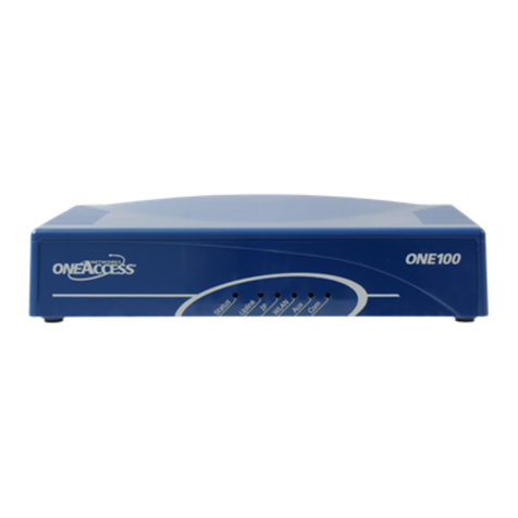
The front panel is provided with LEDS, which inform about the status of several
router functions.
Figure 1. Front panel

ONE100 - Installation Manual
14
Leds OFF Green Red Orange Blinking green
Status Switched Off Switched On &
Operational Switched On &
Not operational Reboot in
progress
Uplink Not used DSL Synchronized Loss of
synchronization Synchronization
in progress
IP Not used All IP interfaces are
up All IP interfaces
are down At least one
IP Interface is
not up
(example:
PPPoA not
connected)
WLAN Not used Interface up Traffic in
progress
Aux Configured and
operational voice
service
Malfunction in
voice service Voice service
configured,
verification of
voice function in
progress.
Com No voice
communication Voice Compression
operational on one
or several channels

ONE100 - Installation Manual
15
3.3 Rear Panel
This section details the various types of ONE100 rear panel so that the user can
identify the interface type and port numbering. It should be noted that only the fully-
loaded configurations are represented. Other configurations can be derived by not
providing some interfaces represented on the product.
3.3.1 Configuration with 4 ISDN
The interface marking is indicated in bold and between bracket.
All the connectors are located on the rear panel:
•1 ADSL 2/2 + access (RJ11) (ADSL)
•1 console port (RJ45) (CONSOLE),
•4 Ethernet ports (RJ45) (SWITCH – E0-0/0 - E3-0/3),
•0 to 4 ISDN access S0/T0 (RJ45) (ISDN BRI – L0-5/0 - L3-5/3),
•2 connectors for WLAN antenna,
•Input for the external power supply connector (DC input jack, 12V-1, 7A).
Figure 2. Rear panel with 4 BRI configuration
Depending of the ordered configuration of the system, the rear panel may
change.

ONE100 - Installation Manual
16
3.3.2 Configuration with FXS/FXO/PSTN board
The interface marking is indicated in bold and between bracket.
All the connectors are located on the rear panel:
•1 ADSL 2/2+ access (RJ11) (ADSL),
•1 console port (RJ45) (CONSOLE),
•1 optional LAN 100 Mbps (RJ45) (ETHERNET),
•4 Ethernet ports (RJ45) (SWITCH – E0-0/0 - E3-0/3),
•4 analog telephone interfaces to connect telephones (FXS interface) (RJ45),
(FXS – L0-5/0 – L3-5/3),
•1 analog telephone access to connect telephone line (FXO interface) (RJ45),
(FXO – L4-5/4),
•1 modem access PSTN (RJ45) (PSTN),
•2 V.28 interface (V.28 – S0 - S1),
•2 connectors for WLAN antenna,
•Input for the external power supply connector (DC input jack, 12V-1, 7A).
Figure 3. Rear panel with FXS/FXO/PSTN configuration
Depending of the ordered configuration of the system, the rear panel may
change.

ONE100 - Installation Manual
17
3.3.3 Configuration with 8 FXS/1 FXO
The interface marking is indicated in bold and between bracket.
All the connectors are located on the rear panel:
•1 ADSL 2/2 + access (RJ11) (ADSL),
•1 console port (RJ45) (CONSOLE),
•Optional, 1 LAN 100 Mbps access (RJ45) (ETHERNET),
•4 communication ports (RJ45) marked (SWITCH – E0-0/0 - E3-0/3),
•8 analog telephone accesses to connect telephone (FXS interface) (RJ45),
marked (FXS – L0-5/0 – L7-5/7),
•1 analog telephone access to connect telephone line (FXO interface) (RJ45),
marked (FXO – L8-5/8),
•2 connectors for WLAN antenna,
•Input for the external power supply connector (DC input jack, 12V-1, 7A).
Figure 4. Rear panel with 8 FXS, 1 FXO configuration
Depending of the ordered configuration of the system, the rear panel may
change.

ONE100 - Installation Manual
18
3.3.4 Configuration with 4 BRI/ 2 FXS
The interface marking is indicated in bold and between bracket.
All the connectors are located on the rear panel:
•1 ADSL 2/2+ access (RJ11) (ADSL),
•1 console port (RJ45) (CONSOLE),
•1 optional LAN 100 Mbps (RJ45) (ETHERNET),
•4 Ethernet ports (RJ45) (SWITCH – E0-0/0 to E3-0/3),
•4 ISDN S0/T0 (RJ45) (ISDN BRI – L0-5/0 to L3-5/3),
•2 analog telephone interfaces to connect telephones (FXS interface) (RJ45),
(FXS – L4-5/4 to L5-5/5),
•2 connectors for WLAN antenna,
•Input for the external power supply connector (DC input jack, 12V-1, 7A).
Figure 5. Rear panel with 4 BRI, 2 FXS configuration
Depending of the ordered configuration of the system, the rear panel may
change.

ONE100 - Installation Manual
19
3.3.5 Configuration with 1 FXS + 1 FXO + 1 ISDN
The interface marking is indicated in bold and between bracket.
All the connectors are located on the rear panel:
•1 ADSL 2/2+ access (RJ11) (ADSL),
•1 console port (RJ45) (CONSOLE),
•1 optional LAN 100 Mbps (RJ45) (ETHERNET),
•4 Ethernet ports (RJ45) (SWITCH – E0-0/0 - E3-0/3),
•1 backup ISDN access (ISDN – L0-5/0),
•4 analog telephone interfaces to connect telephones (FXS interface) (RJ45),
(FXS – L1-5/1 – L4-5/4),
1 analog telephone access to connect telephone line (FXO interface) (RJ45),
marked (FXO – L5-5/5),
•1 modem access PSTN (RJ45) (PSTN),
•2 connectors for WLAN antenna,
•Input for the external power supply connector (DC input jack, 12V-1, 7A).
Figure 6. Rear panel with FXS/FXO/ISDN
Depending of the ordered configuration of the system, the rear panel may
change.

ONE100 - Installation Manual
20
3.3.6 Configuration with 4 + 4 BRI
The interface marking is indicated in bold and between bracket.
All the connectors are located on the rear panel:
•1 ADSL 2/2+ access (RJ11) (ADSL),
•1 console port (RJ45) (CONSOLE),
•4 Ethernet ports (RJ45) (SWITCH – E0-0/0 - E3-0/3),
•4 ISDN S0/T0 (RJ45) (ISDN BRI – L0-5/0 - L3-5/3),
4 ISDN S0/T0 (RJ45) (ISDN BRI – L4-5/4 – L7-5/7),
•2 connectors for WLAN antenna,
•Input for the external power supply connector (DC input jack, 12V-1, 7A).
Figure 7. Rear panel with 4 + 4 BRI
Depending of the ordered configuration of the system, the rear panel may
change.
Other manuals for ONE100
2
Table of contents
Other OneAccess Network Router manuals