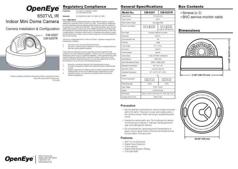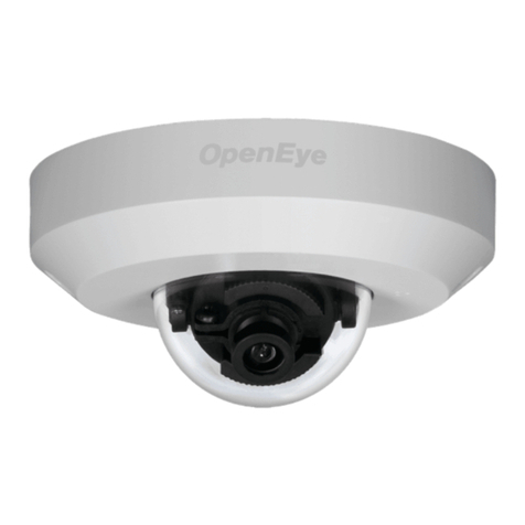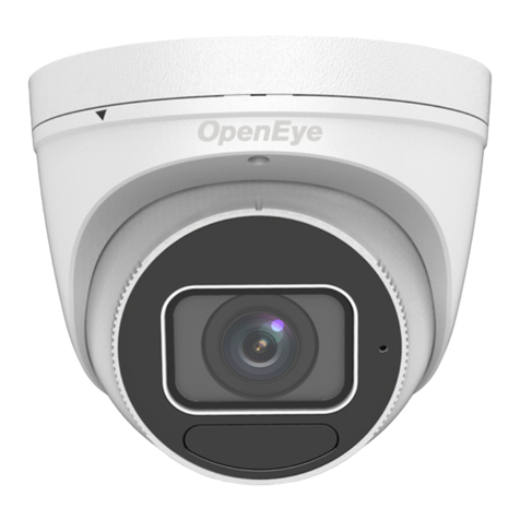
Ceiling Mounting Installation
Before you start:
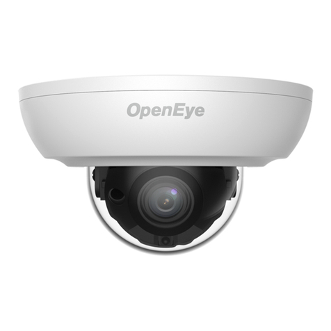
Both wall mounting and ceiling mounting are suitable for the
dome camera. Ceiling mounting will be taken as an example in
this section. And you can take steps of ceiling mounting as a
reference for wall mounting.
Steps:
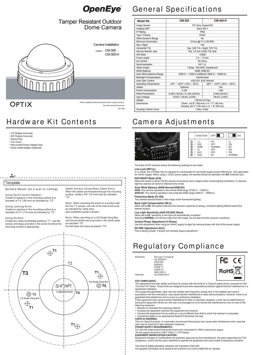
1. Paste the drill template to the ceiling.
2. Drill screw holes and the cable hole (optional) on the ceil-
ing according to the supplied drill template.
Note: Drill the cable hole when adopting the ceiling outlet
to route the cable.
3. Loosen the screws on the bubble of the dome camera to
remove the bubble and the black liner
4. Attach the back box of type I camera/base plate of type
II camera to the ceiling and secure them with supplied
screws.
Note: The supplied screw package contains self-tapping
screws, and expansion bolts.
For cement wall, expansion bolts are required to fix
the camera. For wooden wall, self-tapping screws are
required.
5. Route the cables through the cable hole, or the side
opening.
6. Align the camera with the back box/base plate, and
tighten the screws to secure the camera with the back
box/base plate.
7. Connect the corresponding cables, such as power cord,
and video cable.
8. Power on the camera to check whether the image on
the monitor is gotten from the optimum angle. If not,
adjust the camera according to the figure below to get an
optimum angle.
9. Prior to reattaching the dome, verify the alignment of
the dome gasket and realign the gasket if necessary.
Failure to properly realign the gasket could result in water
ingression and potentially void the camera warranty.
10. Fit the black liner back to the camera and tighten the
screws on the bubble of the dome camera to finish the
installation.
Accessing the Camera’s
On-Screen Menu
Autofocus and Zoom Control
Locally Access OSD Menu
This camera has an on-screen menu for adjusting camera
settings. In order to operate this menu the camera must be
connected to a device that supports UTC control.
1. Connect Camera to a recorder or device which supports
HD-TVI and UTC.
This camera is equipped with an autofocus motorized lens. In
order to control the zoom and focus controls you will need to
trigger them through the camera’s on-screen menu.
1. Access the camera’s on-screen menu
2. Select FOCUS on the main OSD menu to enter the
submenu.
3. Select ZOOM+, ZOOM-, FOCUS+ or FOCUS- to zoom
and focus your camera
a. The camera will automatically focus when you
adjust the zoom
For more information on setting up your HD-TVI camera please
visit openeye.net/support/faqs or contact Technical support at
1-888-542-1103.
The OE-C3442-AWR camera is equipped with a multi-positon
switch that allows you to locally access the OSD menu.
1. Press the center Menu Button to enter the menu.
2. Use the Menu Directional Buttons to navigate to the
desired sub-menu.
3. Press the Menu Button again to enter the sub-menu and
navigate to the desired setting.
4. Navigate to the main menu page to save and exit the
OSD menu to retain your setting’s.
Camera OSD Menu
AE BRIGHTNESS 1-10 Higher values
produce brighter
images
EXPOSURE
MODE
GLOBAL Normal exposure
mode
BLC: 0-8 Backlight
compensation:
improved close
range clarity, poorer
background clarity
WDR Wide Dynamic
Range balances
images brightness
level
AGC HIGH Auto Gain Control
improves image
clarity in poor light
conditions
MIDDLE
LOW
OFF
SENSE UP 0-16 Increases exposure
on signal frame to
make camera more
sensitive to light and
allow production of
low lux images
AWB MODE ATW White balance
adjusts
automatically
according to color
temperature of
scene illumination
MWB Set 1-255
R GAIN/B GAIN to
adjust shades of
red/blue color in
image
RETURN
DAY &
NIGHT
MODE Color Image is colored all
the time
B/W Image is black and
white all the time,
and IR LED turns
on in low-light
conditions
AUTO Turn on/off Infrared
and set value of
Smart IR (1-8)
Infrared Turn on/off IR
LED to meet
requirements
of different
circumstances
Smart IR Set 1-8 to adjust
light to prevent
overexposure
RETURN
VIDEO
SETTINGS
CONTRAST 1-10 Enhances difference
in color and light
SHARPNESS 1-10 Determines amount
of detail an imaging
system can
reproduce
COLOR GAIN 1-10 Change color
saturation
3D DNR 1-10 Decreases noise
effects when
capturing moving
images in low light
conditions
MIRROR DEFAULT Mirror function is
disabled
H Image flips 180°
horizontally
V Image flips 180°
vertically
HV Image flips 180°
both horizontally
and vertically
RETURN
FUNC PRIVACY 4 configurable
privacy areas
Designate areas
you don’t want
recorded. Select a
PRIVACY area, set
DISPLAY status as
ON, click up/down/
left/right button
to define position
and size
MOTION 4 configurable
motion areas
Designate motion
detection areas.
Select a MOTION
area, set DISPLAY
status as ON, click
up/down/left/right
button to define
position and size,
set SENSITIVITY
from 0-100
CAMERA ID Editable
camera ID
Set Camera ID. Set
MODE as ON, click
up/down/left/right
button to position ID
RETURN
RESET Reset all settings to
default
SAVE &
EXIT
Save settings and
exit menu
2. Enable and navigate the on-screen menu using the
devices PTZ interface or dedicated UTC function
a. Most HD Analog Recorders that have UTC
capability utilize the PTZ control menu to access
and navigate the on-screen menu
b. Consult the manufacturers product manual for
specific instructions on UTC or PTZ control
Note: When connecting to an OpenEye M-Series recorder
you must use OWS Command Station and its PTZ controls to
access the cameras on-screen menu. Please see your OWS
Command Station Manual for further instruction on accessing
the camera’s OSD menu.

