threshold with your laser pulses. If the slide is damaged, then either
enlarge your beam or lower the laser energy until damage is no longer
seen.
To measure energy:
1. Set “Measuring” to Energy.
2. Set measurement parameters as described above.
3. Energy will be displayed on the screen as well as the laser’s
frequency.
To measure average power:
1. Set “Measuring” to Power.
2. Set measurement parameters as described above.
3. Average power will be displayed as a function of Energy x Frequency
will be displayed on the screen as well as the laser’s frequency.
To measure exposure:
1. Set “Measuring” to Exposure.
2. Set measurement parameters as described above.
3. Set Stop Mode to manual, time period, or pulse count.
4. Accumulated energy exposure will be displayed on the screen as well
as elapsed time and number of pulses measured.
5Graphical Displays
To present measurements on a graduated scale:
1. Press “Menu” and enter “Display”. Go to “Graph Type” and select
Bargraph. Return to main display screen.
2. To expand the bargraph scale ±5x about the present reading, press the
“Zoom” button. Press the “Zoom” button again to return the bargraph to
full scale.
3. To subtract background and set current reading to zero, press the
“Offset” button. Press “Offset” again to cancel.
To simulate an analog needle:
1. Press “Menu” and enter “Display”. Go to “Graph Type” and select
Needle. Return to main display screen.
2. To expand the needle graph ±5x about the present reading, press
the “Zoom” button. Press the “Zoom” button again to return the needle
range to full scale.
3. To subtract background and set current reading to zero, press the
“Offset” button. Press “Offset” again to cancel.
4. Press “Persist” to keep older measurements on screen and to show
Min and Max measured. Press “Persist” again to cancel.
To graph laser output over time:
1. Press “Menu” and enter “Display”. Go to “Graph Type” and select Line.
Return to main display screen.
2. Set the percentage range of the scale to be displayed to desired setting.
3. Set the horizontal sweep time as necessary.
4. Press “Reset” to clear the Min/Max tracking and to restart the graph.
5. Especially useful to fine-tune laser power.
2Thermal Sensors
2.1. Use of StarBright with Thermal Type Sensors
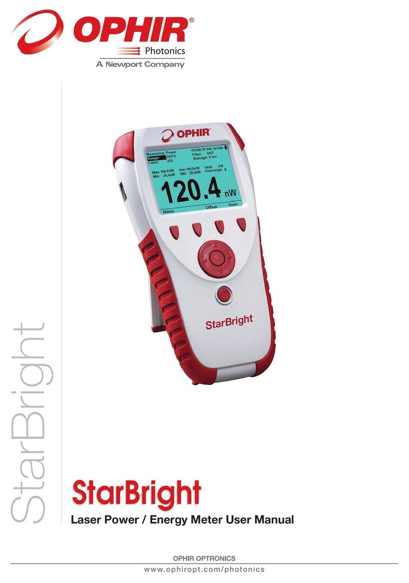
1. Plug in the thermal sensor. StarBright will reconfigure itself to work with
the attached sensor.
2. All of the sensor’s measurement parameters are shown on the main
screen. Use the Navigation keys to select and change the parameters.
3. Use the Navigation keys to select the parameter to change and press
Enter. Change the setting with the Navigation keys. Press Enter to save.
4. StarBright saves the changes automatically for next startup of the
instrument.
Warning:
Do not exceed maximum sensor limits for power, energy, power density
and energy density as listed in the main manual. Otherwise, there is a risk
of damaging the absorber.
2.2. To use the StarBright to Measure Laser Power
1. Set “Measuring” to Power.
2. Set “Range” to AUTO or one of the manual ranges. The correct manual
range is the lowest one that is larger than the expected maximum power
of the laser.
3. Set “Wavelength” to the appropriate laser wavelength.
4. Set “Average” to the period you wish to average power over or set to
“NONE” to disable.
2.3. To use the StarBright to Measure Single Shot Energy
1. Set “Measuring” to Energy.
2. Set “Range”. In Energy mode there is no autoranging. The correct
range is the lowest one that is larger than the expected maximum pulse
energy of the laser.
3. Set “Wavelength” to the appropriate laser wavelength.
4. Set “Threshold” if you wish to change the energy threshold.
5. When the StarBright screen flashes “READY” on and off, fire the laser.
3Photodiode Sensors
3.1. Use of StarBright with Photodiode Type Sensors
1. Plug in the photodiode sensor. StarBright will reconfigure itself to work
with the attached sensor.
2. All of the sensor’s measurement parameters are shown on the main
screen. Use the Navigation keys to select and change the parameters.
3. Use the Navigation keys to select the parameter to change and press
Enter. Change the setting with the Navigation keys. Press Enter to save.
4. StarBright saves the changes automatically for next startup of the
instrument.
Warning:
Do not exceed maximum sensor limits for power, energy, power density
and energy density as listed in the main manual. Otherwise, there is a risk
of damaging the absorber.
3.2. Setting the Measurement Parameters
1. Set “Range” to the appropriate manual range, autorange or dBm
(logarithmic scale). Note that when selecting a manual range,
the correct range is the lowest one that is larger than the expected
maximum power of the laser.
2. Set “Wavelength” to the correct laser wavelength. If the wavelength
you want is not among the wavelengths listed, select one and press
Modify. Using the up/down keys to change each number and the
right/left keys to move to the next number, key in the wavelength you
want. When finished, press Enter.
3. Set “Filter” to IN or OUT as physically configured on the sensor.
4. Set “Average” to the period you wish to average power over or set
to “NONE” to disable.
4Pyroelectric or Photodiode Energy
Sensors
4.1. Use of StarBright with Energy Sensors
1. Plug in the pyroelectric/photodiode energy sensor. StarBright will
reconfigure itself to work with the attached sensor.
2. All of the sensor’s measurement parameters are shown on the main
screen. Use the Navigation keys to select and change the parameters.
3. Use the Navigation keys to select the parameter to change and press
Enter. Change the setting with the Navigation keys. Press Enter to save.
4. StarBright saves the changes automatically for next startup of
the instrument.
Warning:
Do not exceed maximum sensor limits for power, energy, power density
and energy density as listed in the main manual. Otherwise, there is a risk
of damaging the absorber.
4.2. Zeroing Instrument Against Sensor
For most accurate calibration, you should zero the energy sensor against
the StarBright it is being used with. Proceed as follows:
Make sure the sensor is in a quiet environment and not subject to pulsed
radiation. Press “Menu” and select “Instrument”. Press “Zero” and
“Start”. Wait until “Zeroing completed successfully” appears.
4.3. Setting the Measurement Parameters
1. Set “Range” to the lowest one that is larger than the expected maximum
pulse energy of the laser.
2. Set “Wavelength” to the correct laser wavelength. If this sensor is a
metallic type and if the wavelength you want is not among the
wavelengths listed, select one and press Modify. Using the up/down
keys to change each number and the right/left keys to move to the next
number, key in the wavelength you want. When finished, press Enter.
3. Set “Pulse Length” to the shortest time that is longer than the expected
pulse length. Warning: Incorrect readings will result if pulse length is not
set up correctly.
4. For sensors with the diffuser option, set “Diffuser” to IN or OUT as
physically set on the sensor.
5. Set “Threshold” as necessary to screen out false triggers due to noise.
6. Set “Average” to the period you wish to average power over or set to
“NONE” to disable.
4.4. Energy, Average Power or Exposure Measurement
With the pyroelectric sensor, you have been supplied a test slide with
the same coating as on your pyroelectric detector. You can also obtain
this slide from your dealer. You should use this slide to test the damage


