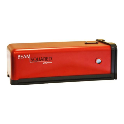
OPHIR Beam Cube User manual

Composite
C M Y CM MY CY CMY K
Beam Cube
INDUSTRIAL LASER BEAM ANALYZER
USER MANUAL
Beam Cube
Beam Cube
www.ophiropt.com
OPHIR OPTRONICS

Rev B1.31-U2.30-1
March-12-2008
Initial Revision

Beam Cube User Guide Introduction
iii
Contents
1Introduction ...................................................................... 5
1.1 Manual Overview.................................................................5
1.2 System Requirements.........................................................6
2System Components and Setup ..................................... 7
2.1 Package Contents...............................................................7
2.2 Beam Cube Assembly.........................................................7
2.3 Beam Cube External Interfaces ..........................................8
3Software Installation and Registration......................... 10
3.1 Spiricon SP Camera Registration and Installation ............10
3.2 StarLab Software Installation (optional) ............................10
3.3 Oscilloscope Software Installation (Optional)....................11
4Setting up for Measurements........................................ 12
4.1 Positioning the Beam Cube and the Laser Under Test.....12
4.2 Electrical Connections.......................................................13
4.3 Setup for Beam Profiling and Operation............................14
4.4 Setup for Power/Energy Measurement using the USB
Interface............................................................................18
4.5 Setup for Temporal Pulse Shape Measurement ...............19
5Beam Profile Measurement ........................................... 21
5.1 Default Startup ..................................................................21
5.2 Add Panel..........................................................................22
5.3 2D Display.........................................................................23

Contents Beam Cube User Guide
iv
5.4 Numerical Values..............................................................24
5.5 Profile Graphs ...................................................................25
5.6 1D Gaussian Fit.................................................................26
5.7 1D Top Hat Fit...................................................................27
5.8 Report Generation.............................................................28
5.9 Beam Wander ...................................................................29
5.10 3D Display.........................................................................29
5.11 Video Data Control............................................................30
5.12 Region of Interest..............................................................31
5.13 Major/Minor Axes ..............................................................32
5.14 Automation........................................................................33
6Power Measurement ...................................................... 34
6.1 Starting and Ending a StarLab Application Session..........34
6.2 Configuring the Display for Power Readings.....................35
7Specifications................................................................. 40
8Ordering Information ..................................................... 42

Beam Cube User Guide Introduction
1 Introduction
The quality and repeatability of laser material processing
is critically dependent on control of the various laser
parameters from production run to production run. The
Beam Cube now allows the operator to measure and
monitor these parameters for industrial Nd:YAG, Diode
and Fiber laser systems of up to 150W average power in
real time and thus closely control the process. It does this
by combining the Beam Profiling capabilities of the
Spiricon series of cameras with the power and temporal
pulse shape measurement capabilities of Ophir’s BA
series.
The user should also check Ophir’s Web page for the latest
updates and FAQs not covered in this manual.
5
Note: This manual is a companion to the BeamStar
User Manual that is included in the Beam Cube
package. All features of the BeamStar software are
available with the Spiricon camera that is embedded in
the Beam Cube.
1.1 Manual Overview
This manual describes the following:
•System Requirements and Components
•Overview of Beam Profiling Capabilities
•Power and Energy Measurement
•Temporal Pulse Shape Analysis

Introduction Beam Cube User Guide
1.2 System Requirements
•Pentium 4, at least 1.7 GHz (>2 GHz for best
performance)
•256 MB of memory
•USB 2.0 port
•Windows XP SP2, Windows Vista-32
•Free USB port on the PC
6
Note: Windows stores all installation information in the
Windows Registry. Therefore, when installing any of the
software components or when attaching the Beam Cube
or USB Interface for the first time, the user must be
logged in with Administrator Privileges.

Beam Cube User Guide System Components and Setup
7
2 System Components and Setup
2.1 Package Contents
The Beam Cube package comes with the following
components
•Beam Cube Assembly
•Beam Cube User Manual
•BeamStar User Manual
•USB cable
•External cable for Thermal head
•BNC to BNC cable
•BeamStar installation CD-Rom
•Ophir Displays CD-Rom
2.2 Beam Cube Assembly
The Beam Cube Assembly contains the following
components
•Spiricon SP503U camera for Beam Profiling (or
SP620U camera in Beam Cube 620 version)
•2 Beam Splitters to reduce the power intensity of
the laser beam as it hits the Spiricon camera by a
factor of 400:1
•A negative imaging lens to expand the size of the
laser beam by a factor of 2-3 while moving the
focal point out, thereby enabling profiling of focal
spots as small as 50µm in size. The lens can also
be removed to measure parallel beams of up to
7mm in size. A -100mm lens is supplied with the
system. Other focal lengths can be purchased if
necessary.

System Components and Setup Beam Cube User Guide
•Photodiode Trigger to enable synching Beam
Profile measurements with pulsed lasers and to
look at the temporal beam shape.
•Variable Attenuator to further reduce the intensity
of the laser beam as it strikes the Spiricon SP
camera
•An Ophir 100C power meter capable of measuring
100W continuously and 150W for short periods.
8
Figure 1: View of components of Beam Cube
Assembly
Beam splitters
SP beam
profiler unit
A
ttenuators
2nd rod
1st rod
Optical trigger
Ophir 100C power meter
Exchangeable input
negative lens
2.3 Beam Cube External Interfaces
The Beam Cube Assembly has 5 external interfaces
•Entrance window for laser beam under test
•USB socket for the Spiricon SP camera

Beam Cube User Guide System Components and Setup
•Connector to attach the power head to power meter
or USBI device
•BNC Output to oscilloscope
•Handles to adjust the Variable Attenuator
Figure 2: Beam Cube with complete casing
9

Software Installation and Registration Beam Cube User Guide
3 Software Installation and Registration
3.1 Spiricon SP Camera Registration and Installation
Spiricon SP camera registration and BeamStar FX
software installation is described fully in the BeamStar
User Manual. A short summary is described here. If any
trouble is encountered in the course of
installation/registration, turn to the BeamStar User Manual
1. Connect the Beam Cube via its USB connector to
the PC.
2. Windows will start its Found New Hardware
Wizard. Press Cancel.
3. Insert the BeamStar FX distribution CD-ROM in
the CD-ROM drive.
4. To start the installation, locate and double-click the
setup icon (setup.exe).
5. When the Choose Installation Type window
appears, select Standard.
10
Note: You must have administrative privileges to install
the software and register the Beam Cube’s Spiricon SP
camera.
3.2 StarLab Software Installation (optional)
If you have purchased the USB Interface to display the
laser power then proceed as follows:
1. Start your computer.
2. Insert the CD into the CD-ROM drive.
3. The CD software should start automatically. If it
does not, double-click index.htm from the CD-
ROM drive to start the software.
4. Under the main heading, click USBI.

Beam Cube User Guide Software Installation and Registration
5. Click Install StarLab. The InstallShield™ Wizard
dialog box appears. The InstallShield™ Wizard
guides you through the installation process. At the
end of the process, the StarLab icon , appears
on the desktop.
The software installation is complete. You can now
connect the USBI or Pulsar device.
3.3 Oscilloscope Software Installation (Optional)
The Beam Cube can be connected directly to an
oscilloscope, thereby enabling temporal pulse width
analysis.
Users may wish to see the temporal pulse shape on their
PC instead. This can be done by using the optional PC
oscilloscope (P/N SPE10008).
Install the oscilloscope application from the CD that
came with the oscilloscope device
11

Setting up for Measurements Beam Cube User Guide
4 Setting up for Measurements
4.1 Positioning the Beam Cube and the Laser Under
Test
The Beam Cube is designed to look at converging beams
either at the focal spot or at some point before the focal
spot so the CCD camera should always be at a point before
the focal spot or at the focal spot. The Beam Cube should
never be placed so far from the source that the focal
spot comes before the camera. This can result in
damage to components inside the Beam Cube when the
laser is run at full power.
In order to facilitate proper setup and positioning of the
Beam Cube, we have provided on the CD included an
Excel program "Setup Program for YAG FSA and
Beam Cube" to help you calculate where to place the
Beam Cube. There are two positions given, the position
that will show the focal spot and the position where the
image will be the largest it can be within the size of the
camera CCD.
12
Note 1: The same Excel program works for Beam Cube
except you should change the Height of CCD in smaller
dimension C from 5.4 to 4.7 before calculation
Note 2: A -100mm negative lens has been provided
with the Beam Cube. If the -100mm lens does not
have sufficient power for the beam focus to reach the
CCD, try -50mm. This alternative lens can be ordered if
necessary. Note that the magnification should optimally
be in the range 1.8 – 3 times

Beam Cube User Guide Setting up for Measurements
In the example above, the source laser has a 100mm focal
length lens which is recessed 10mm into the laser housing
giving 90mm distance from the closest approach to the
laser to the focal point. The beam size at the exit from the
laser is 15mm and the largest beam size on the SP503
camera inside the Beam Cube is 4.7mm and on the SP620
camera inside the Beam Cube 620 is 5.4mm (see note 1
above). As can be seen, the top of the Beam Cube should
be placed between 23.6mm from the source to 36.7mm
from the source to see from the largest sized beam (before
the focal point) to the smallest (at the focal point).
Place the Beam Cube with the input lens directly beneath
the laser. Use the leveling feet if necessary to level the unit
to be exactly perpendicular to the beam. Using the Excel
program provided, place the Beam Cube at a distance
midway between the limits given.
The negative lens in the Beam Cube not only moves the
focal point further from its original position, it also
magnifies the image by the factor given in the Excel
program (by a factor of 2.1 in the example above)
4.2 Electrical Connections
The following diagram shows how to setup the connections of
the Beam Cube (when using the optional USB Interface and
13

Setting up for Measurements Beam Cube User Guide
PC scope to see everything on the PC. You can also use a
regular Ophir smart display and regular oscilloscope).
1. Camera. Connect the USB to USB cable between the PC
outlet of the Beam Cube and the USB2.0 port on the PC
2. Power meter. Connect the D15 to D15 cable between the
power meter outlet of the Beam Cube and the power meter. If
using the USB Interface, also connect the USB to USB cable
between the USBI and the PC.
3. Oscilloscope. Connect the BNC to BNC cable between the
scope output of the Beam Cube and the oscilloscope. If you
are using the PC scope, connect to the PC scope to the PC
with the USB cable.
Figure 3: Electrical Connections of Beam Cube
(when used with USB Interface and PC scope)
14
4.3 Setup for Beam Profiling and Operation
Note: Configuring the camera for the specific laser under
test is detailed fully in chapters 4 and 5 of the BeamStar
USB
PC or Laptop
USB2.0 USB
Beam Cube
CAMER
A
POWER
METER
SCOPE
PC Scope
USB Interface USB to USB cable
D15 to D15 cable USB to USB cable
USB to USB cable
BNC to BNC cable

Beam Cube User Guide Setting up for Measurements
User Manual included. If you are using the LBA software
instead, consult the LBA instructions. A short summary
using BeamStar is described here. If any trouble is
encountered in configuring the camera, please turn to the
BeamStar User Manual
Quick Start Instructions
1. Position Beam Cube directly under laser at the correct
distance from the output lens of the laser as calculated
in the Excel program "Setup Program for YAG FSA
and Beam Cube" we have provided on the CD
included.
2. Connect up as in Figure 3: Electrical Connections of
Beam Cube above.
15

Setting up for Measurements Beam Cube User Guide
16
Figure 4: Camera Format Tab
3. Select the Camera Format Tab of the Control
Panel (lower left corner of the BeamStar display)
4. Set the Optical Scale Factor to “Beam Expanded”.
Set Times to the value given in the Excel program
(magnification factor). Later on we will measure
the expansion factor more accurately.
5. If working with a CW or high rep rate laser, set the
trigger mode to internal by deselecting all the
Trigger options.
6. If working with a pulsed laser, select the BeamStar
Photodiode Accessory and the External Trigger
options.
Note: The default setting when selecting trigger
mode is pulse widths of 3ms. If your pulses are
longer than that, adjust the "Speed" to be somewhat
longer than your pulse width. (see Figure 5 below).
7. If the laser’s pulses are shorter than 20
microseconds, select the Pre-Trigger option.
Otherwise do not select Pre-Trigger.
8. To save these settings, from the Menu Bar, select
Tools>>Options and set the Startup option to
“Start the application with last settings”.

Beam Cube User Guide Setting up for Measurements
Figure 5: Camera Exposure Tab
Optimum gain region
9. Turn on laser at low power ~ 10W. Adjust the
attenuator rods so that the 1st rod is all the way out
and the 2nd rod all the way in. (See fig 1).
10. Adjust the Beam Cube position to get the beam
size and position you want. Raise the laser power
to the level you want while adjusting the attenuator
rods so that the camera gain is in the region noted
in Figure 5.
17

Setting up for Measurements Beam Cube User Guide
For details on how to improve signal quality (if necessary),
please refer to the chapter 5 of the BeamStar User Manual
for detailed explanations of Noise Control, Reference
Subtraction, Background Subtraction, and Averaging.
18
Note: The Beam Cube is equipped with a variable
attenuator instead of removable filters. If the BeamStar
Manual suggests to remove a filter, then decrease the
attenuation. If the suggestion is to add a filter, then
increase the attenuation.
4.4 Setup for Power/Energy Measurement using the
USB Interface
(If using an Ophir power meter, connect between the
Beam Cube and your power meter using the included D15
– D15 cable and follow the instructions in your power
meter manual).
1. Connect between the power meter output of the
Beam Cube and head input point on the USBI
instrument with the “external cable for Beam Cube
power head”. This connects the head that is inside
the Beam Cube Assembly to the USBI device.
Figure 6: USBI Device, Head Connector Side
2. Connect the USB cable to the USBI instrument and
to the USB port of your PC.

Beam Cube User Guide Setting up for Measurements
Figure 7: USBI Device: PC - Device Connector Side
3. The LINK LED should flicker momentarily,
indicating USB enumeration of the device.
4.5 Setup for Temporal Pulse Shape Measurement
The following explanation assumes use of the optional PC
oscilloscope accessory. These instructions should be
adapted to the oscilloscope actually used to perform
temporal pulse shape measurement.
1. Perform all steps of “Setup for Power/Energy
Measurement” described above. This is necessary
in order to provide an electrical power supply for
the temporal pulse module inside the Beam Cube
to operate.
2. Connect the PC oscilloscope module to the USB
input of the laptop or desktop using the USB cable
provided and connect the BNC cable from the
Beam Cube to the left side BNC input of the
oscilloscope.
19

Setting up for Measurements Beam Cube User Guide
Figure 8: PC Scope screen
3. Start the PC oscilloscope program from its icon.
4. With the laser operating and the Beam Cube
measuring, set the time scale to a value several
times the laser pulse width, the voltage scale to
auto, the input to DC and channel B to off. Set the
trigger to Auto.
5. After you see the pulse shape, set the voltage scale
to the best value. Set the trigger to ChA and the
trigger level to a point that insures stable readings.
6. If the signal is too high, attenuate it using the
Variable Attenuator levers that are on the side of
the Beam Cube.
7. As a further check that everything is working
properly, lower the time scale so you can see
several pulses on the screen.
20
Table of contents
Other OPHIR Measuring Instrument manuals
Popular Measuring Instrument manuals by other brands

insize
insize ISF-DF Series Operation manual

Tektronix
Tektronix S-4 instruction manual

ACS contsys
ACS contsys Sonicont USN4SP Technical manual

Intellitec
Intellitec Mini-Bus Application Installation and Troubleshooting Guide

TOOLCRAFT
TOOLCRAFT Cross-Line CL8 operating instructions

Xylem
Xylem WTW pH/Cond 3320 quick start guide