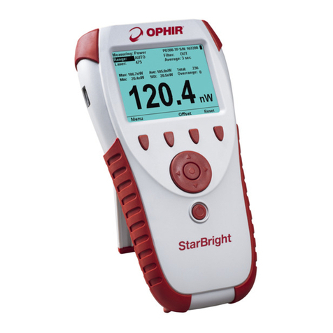
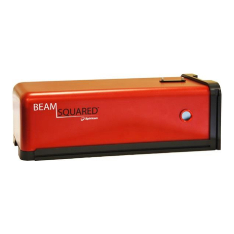
OPHIR StarBright User manual

StarBright
StarBright
StarBright
Laser Power / Energy Meter User Manual

この度はオフィール社のStarBrightディスプレイをご購入頂き誠にありがとうございます。
スターブライト本体のヘルプ機能が充実しており、マニュアルなしでも操作が簡単に行える
ようになっていますが、操作などご不明点ございましたら、お手数ですが下記までお問い
合わせお願いいたします。
Youtubeでも簡単な機能説明についてご覧いtだけます。

StarBright User Manual 1
Table of Contents
1Introduction................................................................................................................... 5
1.1 This Document............................................................................................................... 5
1.2 Related Documentation ................................................................................................ 5
1.3 Support .......................................................................................................................... 5
2Quick Reference............................................................................................................. 6
2.1 Getting Started .............................................................................................................. 6
2.2 Thermopile Sensors....................................................................................................... 7
2.2.1 Using StarBright with Thermopile Type Sensors ...............................................7
2.2.2 Using StarBright to Measure Laser Power.........................................................7
2.2.3 Using StarBright to Measure Single Shot Energy...............................................7
2.3 Photodiode Sensors....................................................................................................... 8
2.3.1 Using StarBright with Photodiode Type Sensors ...............................................8
2.3.2 Setting the Measurement Parameters ..............................................................8
2.4 Pyroelectric or Photodiode Energy Sensors .................................................................. 8
2.4.1 Using StarBright with Energy Sensors................................................................8
2.4.2 Zeroing Instrument against Sensor....................................................................9
2.4.3 Setting the Measurement Parameters ..............................................................9
2.4.4 Energy, Average Power, or Exposure Measurement.......................................10
2.5 Graphical Displays ....................................................................................................... 10
2.6 Math Functions............................................................................................................ 12
2.7 Logging Data to a File for Upload to PC....................................................................... 12
3Using the StarBright Display Unit .................................................................................. 13
3.1 General Description..................................................................................................... 13
3.2 StarBright Display Unit Components........................................................................... 14
3.3 StarBright Hardware Components/Interfaces............................................................. 15
3.3.1 Sensor Input.....................................................................................................15
3.3.2 LCD Display and Backlight................................................................................16
3.3.3 Soft Keys ..........................................................................................................16
3.3.4 Navigation Keys ...............................................................................................16
3.3.5 On-Off Switch/Backlight Control .....................................................................17
3.3.6 Charger Input...................................................................................................18
3.3.7 Analog Output .................................................................................................18
3.3.8 RS232 and USB Outputs...................................................................................19
3.4 StarBright Functions –Independent of Sensor Type................................................... 19
3.4.1 Instrument Settings .........................................................................................20
3.4.2 Field Upgrade –Updating the StarBright Firmware ........................................22
3.4.3 Clock Settings...................................................................................................22
3.4.4 Zero Adjustments ............................................................................................23
3.4.5 Line Frequency.................................................................................................24
3.4.6 Language..........................................................................................................24
3.4.7 Measurement Screens (Graph Types) .............................................................25
3.4.8 Color Scheme...................................................................................................27
3.5 StarBright Screen Layout ............................................................................................. 29

StarBright User Manual 2
4Points to Consider ........................................................................................................ 30
5Thermopile Sensors...................................................................................................... 31
5.1 Operation of StarBright with Thermopile Absorber Sensors ...................................... 32
5.2 Measuring Laser Power with Thermopile Sensors ...................................................... 32
5.3 Measuring Laser Energy with Thermopile Sensors ..................................................... 33
5.3.1 Measuring Pulses of Very Low Energy.............................................................35
5.3.2 Measuring Energy of Rapidly Repeating Pulses...............................................35
6BeamTrack Sensors ...................................................................................................... 36
6.1 Setting Measurement Parameters .............................................................................. 37
6.2 Tracking Laser Beam Position and Size........................................................................ 38
6.3 Tracking Stability - Laser Beam Position Over Time .................................................... 38
7Photodiode Sensors...................................................................................................... 39
7.1 Operation of StarBright with Photodiode Sensors...................................................... 41
7.2 Measuring Laser Power with Photodiode Sensors...................................................... 41
7.3 Averaging and Measuring Very Low Power Measurements ....................................... 43
8Pyroelectric and Photodiode Energy Sensors................................................................. 44
8.1 Pyroelectric Sensors –Method of Operation.............................................................. 44
8.2 Photodiode Energy Sensors –Method of Operation .................................................. 44
8.3 Measuring Pulses of High Energy Density ................................................................... 45
8.4 Operation of StarBright with Pyroelectric and Photodiode Energy Sensors............... 45
8.4.1 Zeroing the Energy Sensor Against the StarBright Meter ...............................46
8.4.2 Setting Measurement Parameters When Using Energy Sensors ....................46
8.4.3 Energy, Average Power, or Exposure Measurement.......................................48
8.4.4 Measuring Laser Energy...................................................................................48
8.4.5 Measuring Average Power...............................................................................49
8.4.6 Measuring Total Energy Exposure ...................................................................50
9Graphical Displays ........................................................................................................ 51
9.1 Display Settings............................................................................................................ 52
9.2 Bargraph ...................................................................................................................... 53
9.2.1 Measuring Modes............................................................................................53
9.2.2 Zoom................................................................................................................54
9.2.3 Offset ...............................................................................................................54
9.2.4 Measuring Loss Using the dB Offset Function.................................................55
9.2.5 Bargraph Style..................................................................................................56
9.3 Analog Needle ............................................................................................................. 58
9.3.1 Measuring Modes............................................................................................59
9.3.2 Persist ..............................................................................................................59
9.4 Line Graph ................................................................................................................... 60
9.4.1 Measuring Modes............................................................................................60
9.4.2 Percentage Range (Y-Axis Scale)......................................................................61
9.4.3 Horizontal Sweep Time (X-Axis Scale) .............................................................61
9.4.4 Reset ................................................................................................................62
9.5 Statistics....................................................................................................................... 62
9.5.1 Measuring Modes............................................................................................63

StarBright User Manual 3
9.6 Pass/Fail....................................................................................................................... 63
9.6.1 Measuring Modes............................................................................................64
9.6.2 Upper/Lower Limits .........................................................................................64
9.7 Exposure (for Pyroelectric Sensors)............................................................................. 65
9.7.1 Measuring Modes............................................................................................66
9.7.2 Manual/Timeout/Pulses ..................................................................................66
9.8 Position (for BeamTrack Sensors)................................................................................ 67
9.8.1 Measuring Modes............................................................................................68
9.9 Stability (for BeamTrack Sensors)................................................................................ 68
9.9.1 Measuring Modes............................................................................................69
9.10 Other Display Settings ................................................................................................. 69
9.10.1 Show/Hide Settings .........................................................................................70
9.10.2 Color Scheme...................................................................................................70
10 Math Functions ............................................................................................................ 73
10.1 Display on Main Measurement Screen ....................................................................... 73
10.2 Functions Screen ......................................................................................................... 74
10.3 Average........................................................................................................................ 75
10.4 Fixed Offset.................................................................................................................. 75
10.5 Scale Factor.................................................................................................................. 76
10.6 Normalize .................................................................................................................... 77
10.7 Density......................................................................................................................... 78
10.8 Function Limitations.................................................................................................... 79
11 Logging Data to a File for Upload to PC ......................................................................... 80
11.1 Launching the Log Setup ............................................................................................. 80
11.2 Setting Logging Parameters for the Various Stop Modes ........................................... 81
11.2.1 Manual Mode ..................................................................................................82
11.2.2 After Timeout ..................................................................................................83
11.2.3 After Measurements........................................................................................85
11.3 Start Logging................................................................................................................ 86
11.4 Displaying Logged Data ............................................................................................... 87
11.5 Viewing the Log File on Your Computer...................................................................... 90
12 Special Sensors............................................................................................................. 91
12.1 BC20............................................................................................................................. 91
12.2 PD300-CIE .................................................................................................................... 92
12.3 PD300-BB..................................................................................................................... 92
12.4 PD300RM..................................................................................................................... 92
12.4.1 Irradiance Measurement.................................................................................93
12.4.2 Dosage Measurement .....................................................................................94
12.4.3 Offset ...............................................................................................................94
12.4.4 Function Limitations ........................................................................................94
13 Circuit Description........................................................................................................ 95
13.1 Analog Module ............................................................................................................ 95
13.1.1 Analog Circuit...................................................................................................95

StarBright User Manual 4
13.1.2 Fast Analog Input.............................................................................................95
13.1.3 Analog Output .................................................................................................95
13.2 Processor Board........................................................................................................... 95
13.2.1 Power Supply ...................................................................................................95
13.2.2 EMI Protection.................................................................................................96
14 Calibration, Maintenance, and Troubleshooting............................................................ 97
14.1 Updating Sensor Calibration Factors........................................................................... 97
14.2 Calibration of Thermopile Sensors .............................................................................. 98
14.2.1 Absorber Types and Method of Calibration of Ophir Power Meters ..............98
14.2.2 Surface Absorbers............................................................................................98
14.2.3 Linearity and Accuracy of Ophir Thermopile Sensors......................................99
14.2.4 Updating Thermopile Sensor Calibration Factors..........................................100
14.3 Calibration of Photodiode Sensors............................................................................ 106
14.3.1 Method of Factory Calibration ......................................................................106
14.3.2 Accuracy of Calibration..................................................................................106
14.3.3 Updating Photodiode Sensor Calibration Factors .........................................107
14.4 Calibration of Pyroelectric Sensors............................................................................ 108
14.4.1 Absorber Types Used in Ophir Pyroelectric Measuring Sensors ...................108
14.4.2 Calibration .....................................................................................................109
14.4.3 Accuracy of Calibration..................................................................................109
14.4.4 Updating Pyroelectric Sensor Calibration Factors.........................................110
14.5 Error Messages .......................................................................................................... 112
14.6 Troubleshooting ........................................................................................................ 112
14.6.1 StarBright Meter............................................................................................112
14.6.2 Thermopile Sensors, Energy Measurements.................................................113
14.6.3 Thermopile Sensors, Power...........................................................................113
14.6.4 Pyroelectric Sensors.......................................................................................113
14.7 Maintenance.............................................................................................................. 114
14.7.1 Maintenance of Thermopile Sensors.............................................................114
14.7.2 Battery Replacement.....................................................................................114
15 StarBright Specifications..............................................................................................115
15.1 System/Meter Specifications..................................................................................... 115
15.2 Sensor Specifications................................................................................................. 117

StarBright User Manual 5
1Introduction
The Ophir StarBright is a microprocessor-based Laser Power/Energy Meter that provides a broad
range of measurements, displays, and data handling options. It operates with Thermopile,
Pyroelectric, and Photodiode sensors. Taking advantage of smart connector technology, it is easy-
to-use—simply connecting the sensor configures and calibrates the StarBright to operate with that
sensor. The sensor configuration and calibration information is stored in an EEROM in the sensor
connector plug. This means that when the sensor is plugged in, StarBright automatically identifies
the sensor type, calibration, and configuration. The user does not have to adjust anything.
The StarBright’s 320x240 full color screen enhances measurement readouts in ways that simple
monochrome displays cannot. The StarBright can graph power or energy versus time. It displays
power measurements in both digital and analog form simultaneously and also has a needle type
display. It will also autorange, so you do not have to set scales; or it can manual range if you wish.
It will remember what mode you were using before you turned it off and will return to that mode
when turned on. You can zoom in on the present reading, or subtract background. Although the
calibration information is stored in the smart connector, you can recalibrate from the screen and
store the new calibration in the sensor. You can also zero the StarBright at the touch of a button.
StarBright is capable of logging data onto a USB Flash Drive (Disk On Key), as well as real-time
reporting of data via USB to Ophir’s StarLab application to display and process the information.
StarBright has RS232 capabilities as well. StarBright also has the infrastructure for field upgrading
of the embedded software, should the need arise.
Above all, the StarBright has advanced circuitry and digital signal processing for excellent
sensitivity, signal to noise ratio, accuracy, and response time. It also has special circuitry to reject
electromagnetic interference.
StarBright’s User Interface is intuitive. The keypad functionality is context-sensitive and functions
according to the needs to the present screen. Where necessary, on-screen help is provided as well,
so you should not have to refer to this manual very often.
1.1 This Document
This document covers everything you need to know to make full use of the StarBright for all your
laser measurement needs. It includes a Quick Reference (Chapter 2) to allow you to perform basic
measurements immediately, without reading the whole manual.
1.2 Related Documentation
Ophir takes pride in the wealth of laser measurement information that we provide including
FAQ’s, Catalogs, Spec Sheets, and more. Go to http://www.ophiropt.com/laser-measurement-
instruments/laser-power-energy-meters.
1.3 Support
If you have a question or require further assistance, contact Ophir customer support at

StarBright User Manual 6
2Quick Reference
This section provides a quick reference for performing basic measurements with the StarBright
Laser Power/Energy Meter.
2.1 Getting Started
The StarBright is equipped with "soft keys." That is, the functions of the keys change as indicated
by the legend above each key. It is also equipped with 4 navigation keys and a round Enter key in
the center.
To connect sensor to the StarBright meter:
Insert the 15 pin D type connector of the measuring sensor cable into the socket
marked Sensor Input on the rear panel of the StarBright meter.
To switch the StarBright on:
1. To switch on, briefly press the On/Off/Backlight switch. The unit will switch on, and the display
will appear.
2. The backlight for the StarBright’s LCD can be configured to toggle between full, half, and low
illumination. This toggling will be performed by briefly pressing the On/Off switch after the
StarBright has been switched on.
3. To switch the StarBright off, press the On/Off switch and hold it for ~ 2 seconds until the
display blanks.
To set general instrument settings:
1. Disconnect the sensor. Use the Navigation keys to select the parameter to change and press
the Enter key. Change the setting with the Navigation keys. Press the Enter key to save.
2. RS232 Baud: Set baud rate for PC communication through its COM port.
3. Max An. Output: Set desired max analog output.
4. Language: Set to desired language.
5. Line Frequency: Set to 50Hz or 60Hz, depending on the electrical power grid of the area that
you are in.
6. Date and Time: Set to correct date and time.
The StarBright automatically saves the current settings for next power up.
To zero the instrument:
1. Disconnect the sensor.
2. Make sure the instrument is not in an electrically noisy environment and is undisturbed.
3. Press Zero and Start. Zeroing takes about 30 seconds. Wait until “Zeroing completed
successfully” appears.

Quick Reference
StarBright User Manual 7
2.2 Thermopile Sensors
2.2.1 Using StarBright with Thermopile Type Sensors
1. Plug in the Thermopile sensor. StarBright will reconfigure itself to work with the attached
sensor.
2. All of the sensor’s measurement parameters are shown on the main screen. Use the
Navigation keys to select and change the parameters.
3. Use the Navigation keys to select the parameter to change and press the Enter key. Change
the setting with the Navigation keys. Press the Enter key to save.
4. StarBright saves the changes automatically for next startup of the instrument.
Warning: Do not exceed maximum sensor limits for power, energy, power density, and energy
density as listed in Sensor Specifications. Otherwise, there is a risk of damaging the absorber.
2.2.2 Using StarBright to Measure Laser Power
1. Set Measuring to Power.
2. Set Range to AUTO or one of the manual ranges. The correct manual range is the lowest one
that is larger than the expected maximum power of the laser.
3. Set Wavelength to the appropriate laser wavelength.
4. Set Average to the period you wish to average power over or set to NONE to disable.
2.2.3 Using StarBright to Measure Single Shot Energy
1. Set Measuring to Energy.
2. Set Range to the appropriate manual range. (In Energy mode, there is no autoranging.) The
correct range is the lowest one that is larger than the expected maximum pulse energy of the
laser.
3. Set Wavelength to the appropriate laser wavelength.
4. Set Threshold if you wish to change the energy threshold.
5. When the StarBright screen flashes READY on and off, fire the laser.

Quick Reference
StarBright User Manual 8
2.3 Photodiode Sensors
2.3.1 Using StarBright with Photodiode Type Sensors
1. Plug in the Photodiode sensor. StarBright will reconfigure itself to work with the attached
sensor.
2. All of the sensor’s measurement parameters are shown on the main screen. Use the
Navigation keys to select and change the parameters.
3. Use the Navigation keys to select the parameter to change and press the Enter key. Change
the setting with the Navigation keys. Press the Enter key to save.
4. StarBright saves the changes automatically for next startup of the instrument.
Warning: Do not exceed maximum sensor limits for power, energy, power density, and energy
density as listed in Sensor Specifications. Otherwise, there is a risk of damaging the absorber.
2.3.2 Setting the Measurement Parameters
1. Set Range to the appropriate manual range, AUTO, or dBm (logarithmic scale). Note that
when selecting a manual range, the correct range is the lowest one that is larger than the
expected maximum power of the laser.
2. Set Wavelength to the appropriate laser wavelength. If the wavelength you want is not among
the wavelengths listed, select one and press Modify. Using the up/down Navigation keys to
change each number and the right/left keys to move to the next number, key in the
wavelength you want. When finished, press the Enter key.
3. Set Filter to IN or OUT as physically configured on the sensor.
4. Set Average to the period you wish to average power over or set to NONE to disable.
2.4 Pyroelectric or Photodiode Energy Sensors
2.4.1 Using StarBright with Energy Sensors
1. Plug in the Pyroelectric/Photodiode energy sensor. StarBright will reconfigure itself to work
with the attached sensor.
2. All of the sensor’s measurement parameters are shown on the main screen. Use the
Navigation keys to select and change the parameters.
3. Use the Navigation keys to select the parameter to change and press the Enter key. Change
the setting with the Navigation keys. Press the Enter key to save.
4. StarBright saves the changes automatically for next startup of the instrument.
Warning: Do not exceed maximum sensor limits for power, energy, power density, and energy
density as listed in Sensor Specifications. Otherwise, there is a risk of damaging the absorber.

Quick Reference
StarBright User Manual 9
2.4.2 Zeroing Instrument against Sensor
For most accurate calibration, you should zero the energy sensor against the StarBright it is being
used with:
1. Make sure the sensor is in a quiet environment and not subject to pulsed radiation.
2. Press Menu and select Instrument.
3. Press Zero and Start. Wait until “Zeroing completed successfully” appears.
2.4.3 Setting the Measurement Parameters
1. Set Range to the lowest one that is larger than the expected maximum pulse energy of the
laser.
2. Set Wavelength to the correct laser wavelength. If this sensor is a metallic type and if the
wavelength you want is not among the wavelengths listed, select one and press Modify. Using
the up/down keys to change each number and the right/left keys to move to the next number,
key in the wavelength you want. When finished, press the Enter key.
3. Set Pulse Length to the shortest time that is longer than the expected pulse length.
Warning: Incorrect readings will result if pulse length is not set up correctly.
4. For sensors with the diffuser option, set Diffuser to IN or OUT as physically set on the sensor.
5. Set Threshold as necessary to screen out false triggers due to noise.
6. Set Average to the period you wish to average power over, or set to NONE to disable.

Quick Reference
StarBright User Manual 10
2.4.4 Energy, Average Power, or Exposure Measurement
With the Pyroelectric sensor, you have been supplied a test slide with the same coating as on your
Pyroelectric detector. You can also obtain this slide from your dealer. You should use this slide to
test the damage threshold with your laser pulses. If the slide is damaged, then either enlarge your
beam, or lower the laser energy until damage is no longer seen.
To measure energy:
1. Set Measuring to Energy.
2. Set measurement parameters as described above.
3. Energy will be displayed on the screen as well as the laser’s frequency.
To measure average power:
1. Set Measuring to Power.
2. Set measurement parameters as described above.
3. Average power will be displayed as a function of “Energy x Frequency”on the screen as well as
the laser’s frequency.
To measure exposure:
1. Set Measuring to Exposure.
2. Set measurement parameters as described above.
3. Set Stop Mode to Manual, Timeout period, or Pulse count.
4. Accumulated energy exposure will be displayed on the screen, as well as elapsed time and
number of pulses measured.
2.5 Graphical Displays
To present measurements on a graduated scale (bargraph):
1. In Power or Energy mode, press Menu and enter Display.
2. Go to Graph Type and select Bargraph. Return to the main display screen.
3. To expand the bargraph scale ±5x of the present reading, press the Zoom button. Press Zoom
again to return the bargraph to full scale.
4. To subtract the background and set the current reading to zero, press the Offset button. Press
Offset again to cancel.
To simulate an analog needle:
1. In Power or Energy mode, press Menu and enter Display.
2. Go to Graph Type and select Needle. Return to the main display screen.
3. To expand the needle graph ±5x of the present reading, press Zoom. Press Zoom again to
return the needle range to full scale.

Quick Reference
StarBright User Manual 11
4. To subtract the background and set the current reading to zero, press the Offset button. Press
Offset again to cancel.
5. Press Persist to keep older measurements on the screen and to display numerically the Min
and Max values measured. Press Persist again to cancel.
To graph laser output over time:
1. In Power or Energy mode, press Menu and enter Display.
2. Go to Graph Type and select Line. Return to the main display screen.
3. Set the percentage range of the scale to be displayed to the desired setting.
4. Set the horizontal sweep time as necessary.
5. Press Reset to clear the Min/Max tracking and to restart the graph.
6. Especially useful to fine-tune the laser power.
To display real-time statistics:
1. In Power or Energy mode, press Menu and enter Display.
2. Go to Graph Type and select Statistics. Return to the main display screen.
3. Displays Maximum, Minimum, Average, Standard Deviation, Total Readings, and Number
Overrange.
4. To subtract the background and set the current reading to zero, press the Offset button. Press
Offset again to cancel.
5. Press Reset to clear the statistics.
To set pass/fail tracking:
1. In Power or Energy mode, press Menu and enter Display.
2. Go to Graph Type and select Pass/Fail. Return to the main display screen.
3. Press the Upper and Lower buttons to set tolerance limits. If reading is out of range, an
appropriate warning will be displayed on the screen.
To track laser beam position and size (BeamTrack sensors only):
1. When in Track mode, press Menu and enter Display.
2. Go to Graph Type and select Position. Return to the main display screen.
3. Press Center to center the laser beam.
4. Press Offset to subtract the background noise from the measurement and reset the value to
zero.
To track laser beam position over time (BeamTrack sensors only):
1. When in Track mode, press Menu and enter Display.
2. Go to Graph Type and select Stability. Return to the main display screen.
3. Press 1 sec to change the time interval (to 3, 10, 30 seconds or 1 minute).

Quick Reference
StarBright User Manual 12
2.6 Math Functions
To apply a fixed offset to measurements:
1. Press Menu and enter Functions. Go to Fixed Offset.
2. Set the value to subtract from all subsequent measurements.
To apply a Scale Factor to measurements:
1. Press Menu and enter Functions. Go to Scale Factor.
2. Set to value by which to multiply all subsequent measurements.
3. Useful when working with beam splitters.
To normalize against a reference measurement:
1. Press Menu and enter Functions. Go to Normalize.
2. Set to reference value by which to normalize all subsequent measurements.
To display as power/energy density:
1. Press Menu and enter Functions. Go to Density.
2. Select beam shape and size.
3. Measurements will be shown as cm².
2.7 Logging Data to a File for Upload to PC
You can log your measurement data to a file for upload to PC by connecting an external storage
device to the USB port of the StarBright meter. For details, see Logging Data to a File for Upload to
PC.

StarBright User Manual 13
3Using the StarBright Display Unit
This section describes the StarBright display unit, its components, its functions independent of
sensor type, hardware functions, GUI, and keypad settings.
Topics include:
General Description
StarBright Display Unit Components
StarBright Hardware Components/Interfaces
StarBright Functions –Independent of Sensor Type
StarBright Screen Layout
3.1 General Description
The Ophir StarBright is a microprocessor-based Laser Power/Energy Meter that provides a broad
range of measurements, displays, and data handling options. It operates with Thermopile,
Pyroelectric, and Photodiode sensors. Taking advantage of smart connector technology, it is easy-
to-use—simply connecting the sensor configures and calibrates the StarBright to operate with that
sensor. The sensor configuration and calibration information is stored in an EEROM in the sensor
connector plug. This means that when the sensor is plugged in, StarBright automatically identifies
the sensor type, calibration, and configuration. You do not have to adjust anything. Sensors are
hot swappable. Even after the meter is switched on, you can remove one sensor and insert a
different one. StarBright will recognize the switch and reconfigure itself according to the settings
of the new sensor.
The StarBright’s 320x240 full-color screen enhances measurement readouts in ways that simple
monochrome displays cannot. The StarBright can graph power or energy versus time. It displays
power measurements in both digital and analog form simultaneously and also has a needle type
display. It will also autorange, so you do not have to set scales; or it can manual range if you wish.
It will remember what mode you were using before you turned it off and will return to that mode
when turned on. You can zoom in on the present reading, or subtract background. Although the
calibration information is stored in the smart connector, you can recalibrate from the screen and
store the new calibration in the sensor. You can also zero the StarBright at the touch of a button.
StarBright is capable of logging data onto a USB Flash Drive (Disk On Key), as well as real-time
reporting of data via USB to Ophir’s StarLab application to display and process the information.
StarBright has RS232 capabilities as well. StarBright also has the infrastructure for field upgrading
of the embedded software, should the need arise.
Above all, the StarBright has advanced circuitry and digital signal processing for excellent
sensitivity, signal to noise ratio, accuracy, and response time. It also has special circuitry to reject
electromagnetic interference.
StarBright’s User Interface is intuitive. The keypad functionality is context-sensitive and functions
according to the needs to the present screen. Where necessary, on-screen help is provided as well,
so you should not have to refer to this manual very often.

Using the StarBright Display Unit
StarBright User Manual 14
3.2 StarBright Display Unit Components
Figure 3-1 below displays the StarBright display unit, displaying the main screen with some sample
measurements.
Figure 3-1 StarBright Meter/Display Unit –Front View
The StarBright is equipped with:
LCD Display screen
Soft keys (under the display screen): The functions of the keys change as indicated by the
legend above each key. (The Menu key enables you to access Sensor, Display, Functions,
Instrument, Log, and Calibration settings. For sensor-specific details, see Thermopile Sensors,
BeamTrack Sensors, Photodiode Sensors, Pyroelectric and Photodiode Energy Sensors.)
4 Navigation Keys and round Enter Key (under the soft keys, in the center of the unit)
Power On/Off/Backlight button

Using the StarBright Display Unit
StarBright User Manual 15
Rear Panel with the following sockets: 12VDC, AN OUT, Sensor Input, RS232, USB OTG
Figure 3-2 StarBright Rear Panel
USB Port (on left side of the StarBright meter)
Figure 3-3 USB Port (on Left Side) of StarBright Meter
3.3 StarBright Hardware Components/Interfaces
This section describes the StarBright hardware components and interfaces.
Topics include:
Sensor Input
LCD Display and Backlight
Soft Keys
Navigation Keys
On-Off Switch/Backlight Control
Charger Input
Analog Output
RS232 and USB Outputs
3.3.1 Sensor Input
The Sensor Input, located in the center of the StarBright real panel, is the socket where you insert
the 15 pin D type connector of the measuring sensor cable in order to connect the sensor to the
meter, as shown in Figure 3-4 below.
Figure 3-4 StarBright Rear Panel View

Using the StarBright Display Unit
StarBright User Manual 16
3.3.2 LCD Display and Backlight
The StarBright screen is a QVGA 320x240 pixel color TFT LCD. It can be driven in one of two full
color modes or in one.
The LCD backlight is actually a set of LEDs that illuminate the display from behind. Because the
StarBright uses a TFT color display, the backlight must be constantly on. It can be operated at full
intensity for full illumination; or at low or half-level to conserve power consumption
(recommended). The backlight level is toggled by a short press on the On/Off switch.
The StarBright backlight consumes considerably less power than competing instruments, and
therefore it can operate from the battery even when the charger is not plugged in. Nevertheless,
since it does shorten the time between charges, it is recommended to set the backlight to less
than full intensity when the instrument is operated without the charger. (For further details, see
On-Off Switch/Backlight Control.)
3.3.3 Soft Keys
The Soft keys, located under the StarBright screen, have functions defined
by the legend above each key. The legend usually indicates what will
happen when pressing the key. For example, if "Zoom" appears above a key, pressing that key will
display a zoom view of the screen. Some functions operate when the key is pressed and are
canceled when the key is pressed again. Those keys show reverse highlighting when operational.
Pressing the same key again cancels the operation and the highlighting.
Key Functions
The StarBright has certain conventions as to the meaning of standard key strokes, including:
Highlighted item: The item that is presently active.
Menu: Provides access to Sensor, Display, Functions, Instrument, Log, and Calibration settings.
Start: Launches the active item.
Exit: Returns to the previous screen.
Cancel: Cancels the selection and returns to the previous screen, leaving the settings
unchanged.
3.3.4 Navigation Keys
The Navigation keys move to the next active item—left, right, up, and down. The round
button in the center is an Enter key to enter the screen of the item selected or when
finished, to leave that screen. Pressing the Enter key to leave the screen will save the
newly selected value for immediate use and will also save the change permanently.

Using the StarBright Display Unit
StarBright User Manual 17
3.3.5 On-Off Switch/Backlight Control
This section describes how to switch on/off the StarBright and how to toggle the state of the
backlight.
To turn the StarBright on:
Briefly press the On/Off switch (located under the Navigation keys, at the bottom
of the front panel). See Figure 3-1 above.
The unit switches on, and the display appears. If no sensor is connected, the Instrument
Settings screen appears, displaying the configurations saved from the previous session (see
Instrument Settings). For example:
Figure 3-5 Instrument Settings Screen
If a sensor is connected, the appropriate default measurement screen will appear. For
example:
Figure 3-6 Needle Display with Persistence Enabled
To switch the StarBright off:
Press the On/Off switch and hold it for ~ 3 seconds until the display blanks.
To toggle the state of the backlight of the StarBright’s LCD:
Briefly press the On/Off switch after the StarBright has been switched on. You can
toggle the backlight between full, half, and low illumination.

Using the StarBright Display Unit
StarBright User Manual 18
3.3.6 Charger Input
The StarBright can be operated either by the internal battery or from an AC source with the
charger plugged in all the time. Plug the charger into the jack labeled "12VDC" on the rear panel
(see Figure 3-7 below). The battery will be charged at the same rate whether the StarBright is
switched on or off, and whatever the backlight level. The battery will fully recharge in around 4-5
hours.
Figure 3-7 StarBright Rear Panel View
Note: The charger circuit of the StarBright is designed to allow the charger to be plugged in for an
extended period without causing damage to the battery.
The approximate time between charges is given in Table 3-1 below for various configurations:
Table 3-1 Sensor Charging Times
Sensor Type
Backlight Level
Time Between Charges
Thermopile and Photodiode
Low
19 hours
Thermopile and Photodiode
Half
17 hours
Thermopile and Photodiode
Full
15 hours
Pyroelectric and BeamTrack
Low
16 hours
Pyroelectric and BeamTrack
Half
15 hours
Pyroelectric and BeamTrack
Full
13 hours
Note: Battery charge will be depleted faster if a USB Flash Drive (Disk on Key) is left plugged into
the StarBright meter.
The battery charge is indicated by the icon. The battery charge is shown approximately by each
segment of the icon, for example, when 2 segments are shown, the battery is ½ full. When the
battery is charging, the segments turn on in sequence. When the battery is low, the charger should
be plugged in. While the unit will charge even while on and even with the backlight on, it will
charge fastest if the charger is left in while the unit is off.
3.3.7 Analog Output
The StarBright provides an analog voltage output via the 2.5mm mono jack socket on the rear
panel marked “AN OUT” (see Figure 3-7 above). The StarBright is supplied with the mating adapter
plug that connects to this socket. The analog output is useful for driving chart recorders and other
analog devices. The voltage is proportional to the reading on the display and scaled such that full
scale equals 1, 2, 5, or 10 volts as selected during setup.
Table of contents
Other OPHIR Measuring Instrument manuals