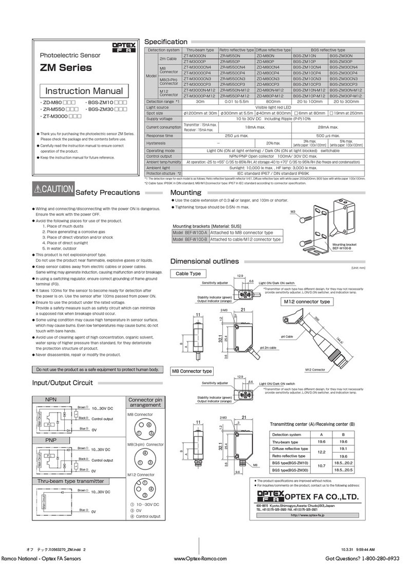
Warning
Indicates that incorrect use may lead to a hazard-
ous situation resulting in injury or death. Also indi-
cates a risk of signicant property damage.
Warning
●This product is not explosion-proof and should not be used around ammable or explosive gases or liquids.
●Doing so may cause injury, re, or electric shock. This product cannot be used as protective equipment
for the purpose of protecting the human body.
Caution
●It is dangerous to wire or attach/remove the connector while the power is on. Make sure to turn off the
power before operation.
●Installing in the following locations may result in malfunction:
1. Dusty or steamy locations. 3. Locations with direct exposure to water or oil
splashes.
2. Locations where corrosive gas is generated. 4. Locations where heavy vibrations or impacts
may occur.
●The product is not designed for outdoor use.
●Do not wire with high voltage cables or power lines. Doing so may cause malfunction or damage by
induction.
●Detection characteristics may vary depending on the state of the target object and variations among
individual products.
●Do not use the product in water.
●Do not disassemble, repair, or modify this product. Doing so may cause injury, re, or electric shock.
●Operate within the rated ranges.
INCLUDED ACCESSORIES
Please conrm that the following accessories are included in the box.
• CVS1-□□□-RA • This instruction manual • Mounting screws (M4 x 50), 2 pcs.
(including washers and nuts)
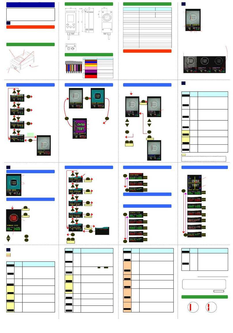
I/O circuit diagram
15 kΩ
7.5 kΩ
Protection diode
*1: Characters in red are settings.
*2: Because 2/3 is set for , operation is performed as "Lower limit input."
●One-point teaching
Bank select 2 /
Teaching input
Bank select 2 /
Teaching input
●Two-point teaching
>3sec. 3sec.
(Start) (Color check) (End)
(Checking at first point) (Checking at second point / End)(Start)
Teach input (pink wire) timing chart (when the specified bank is 0 to 16)
Bank select 3 / Synchronous input (Set using .)
Orange/Black:
Yellow/Black:
Pink:
Purple:
Red/Black:
Black:
Blue:
Brown:
Bank select 0
Bank select 1
Bank select 2 (17/18) / Teaching input (0 to 16)
Lower limit input / Bank select 3 input (18) *2
Judgment output
0 V power
12 to 24 V power
BANK
OUTSIDE
SYNCHRON
Internal circuitInternal circuit
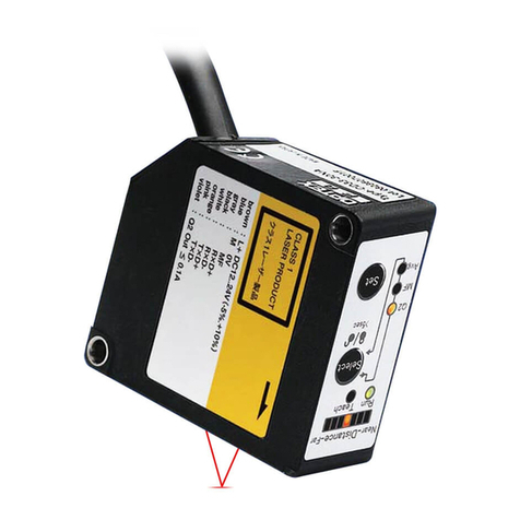
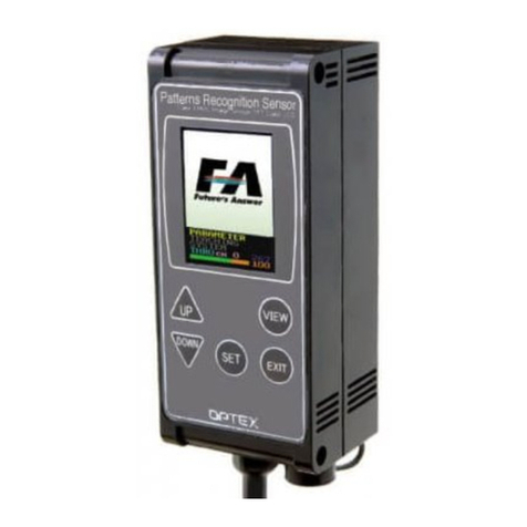
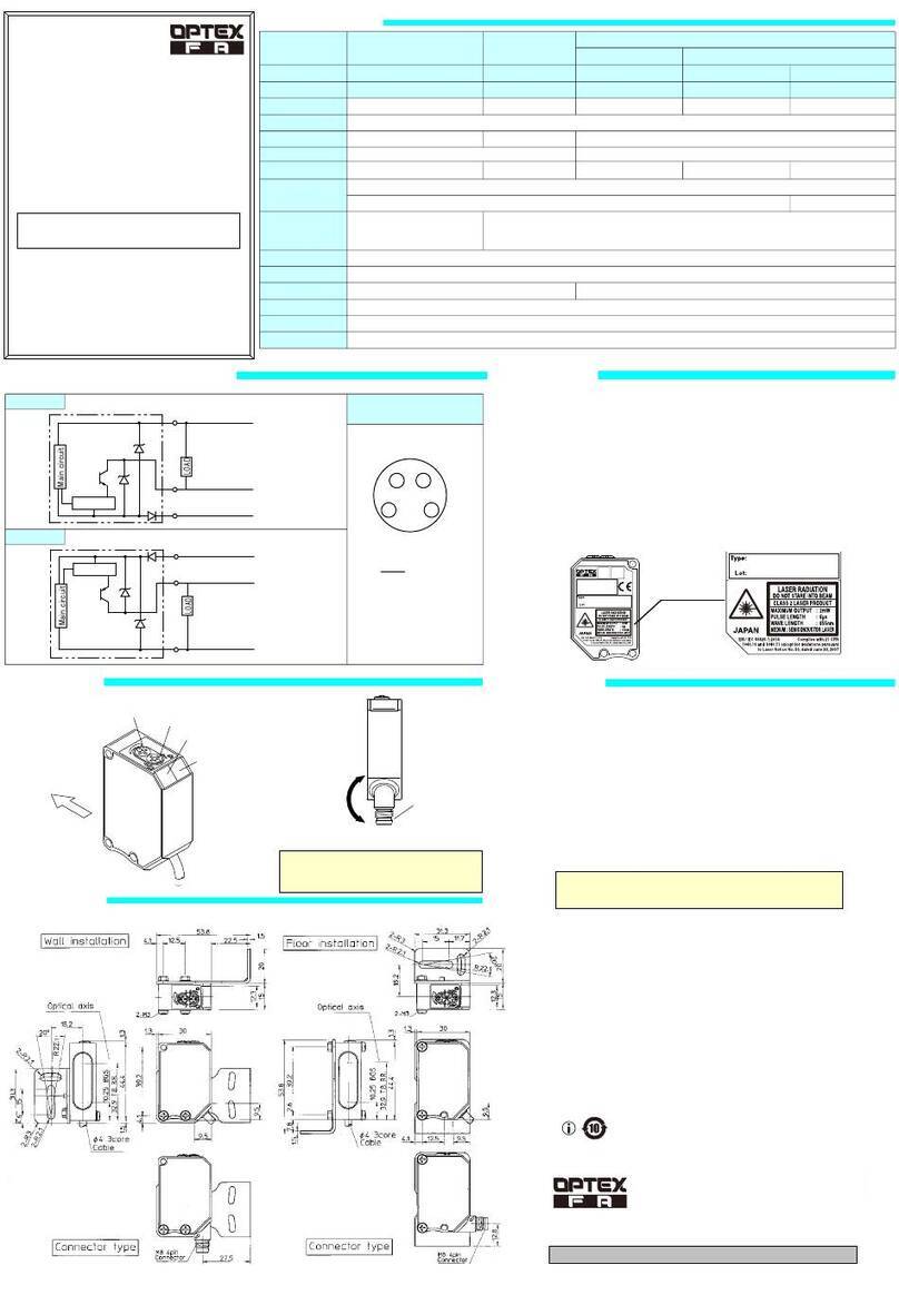
Names of parts
External connector
Power / input/output wire
Camera and lights (back of product)
Operating buttons
LCD screen
Mounting holes
Used for mounting this device.
Use M4 × 50 mm screws or longer.
(φ4.3, pitch: 87 mm, depth: 4 mm)
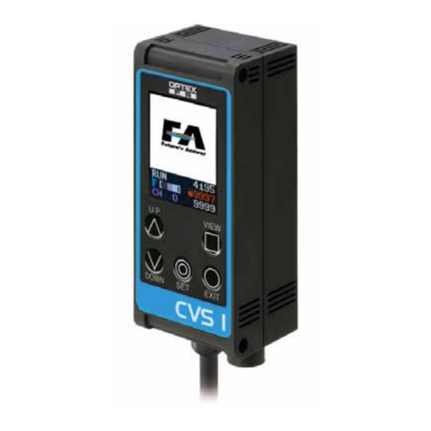
CVS1-RA Series
CVS1-□10-RA CVS1-□20-RA CVS1-□21-RA CVS1-□40-RA
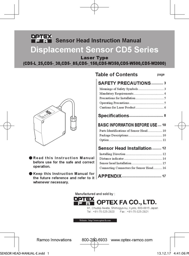
Instruction Manual
●Thank you for purchasing this product. Before using this product, conrm that the
product you have received is the product that you requested.
●Read this instruction manual thoroughly before use, and keep it in a safe location.
Color Area Vision Sensor
Specifications
Model CVS1-N10-RA
CVS1-P10-RA
CVS1-N20-RA
CVS1-P20-RA
CVS1-N21-RA
CVS1-P21-RA
CVS1-N40-RA
CVS1-P40-RA
Detection angle 10° 20° 40°
Working distance 210 to 270 mm 90 to 150 mm 31 to 39 mm 50 to 100 mm
Field of view (±10%)
40 × 50 mm to
55 × 65 mm
40 × 50 mm to
65 × 75 mm
17 × 20 mm 46 x 55 mm to
82 x 98 mm
Light source White LED, 12 pcs. built in
Power supply voltage 12 to 24 VDC
Current consumption Max. 140 mA / 24 VDC
Inspection window size 8×16 to 208×236
Illumination life
Approx. 50,000 hours
(normal temperature and humidity, brightness decreased from initial level by 1/2)
Response time 18.8 ms (initial setting), 15 ms (min.), 36.4 ms (max.)
Output signal NPN/PNP open collector output × 2
Max. 100 mA, 1.0 V residual voltage or less
Input Bank selection / Synchronized / External teaching input × 4
Environmental resistance
Protection category IP67
Operating temperature/
humidity
0 to +40°C/35 to 85%RH (no condensation or freezing)
Storage temperature/humidity
-20 to +70°C/35 to 95%RH (no condensation or freezing)
Vibration resistance
10 to 55 Hz; double amplitude 1.5 mm; 2 hours in each of the X, Y, and Z directions
Shock resistance Approx. 50 G (500 m/s2), 3 times in each X, Y, and Z direction
Applicable regulations EMC compliant (2014/30/EU); RoHS compliant (2011/65/EU)
Applicable standards EN 61000-6-2, EN 61000-6-4
Material Housing: ABS;
Emitter and receiver: Acryl
Emitter and receiver: PC
Weight Approximately 200 g
Dimensions
879595
28.2
11
21
4233.8
29.5
4
2-φ4.3
Tightening torque:
0.8 N・m or less
13.2 15.5
11.2
External connector
Cable length: 2 m
φ5 mm, 8 cores × 0.08 mm²
Heat-resistant soft vinyl Unit: mm
Set the sensor and the workpiece at an angle so
that there is no reflection from the built-in light.
5° to 45°
Options
Category Model Description
Remote monitor
CVS-M1-R
This is the monitor unit for use with the CVS series. This allows results to be
checked away from the workpiece and can be set up similar to the main unit.
Extension cable (3 m)
CVS-C3S This cable extends the dedicated cable or the remote monitor cable.
Up to 4 extension cables can be used (up to 15 m).
External bar light
*Requires power supply for light.
OPB-5015W-B 50 mm white light. Use if reection from internal light is obtrusive.
OPB-10015W-B 100 mm white light. Use if reection from internal light is obtrusive.
Power supply for light
OPPD-15 Required when using an external light.
Mounting bracket for
bar light
CVS-OPDB-2000
This bracket is for vertically mounting the OPB-5015W-B (up to 2 can be used).
CVS-OPDB-3040
This bracket is for horizontally mounting the bar light (up to 2 can be used).
Horizontal adjustment up to 30 mm and vertical adjustment up to 40 mm is possible.
CVS-OPDB-6080
This bracket is for horizontally mounting the bar light (up to 2 can be used).
Horizontal adjustment up to 60 mm and vertical adjustment up to 80 mm is possible.
Display description
RUN
F [ ]
CH
0
5000
9999
9999
(1)
(6)
(2)
(3)
(4)
(5)
(7)
(9)
(8)
Number
Name Explanation
(1)
Imaging screen
The image taken by the camera is displayed according to "Screen display mode."
(2)
Mode display
• Operation screen: "RUN" is displayed.
• Settings screen: The settings are displayed.
(3)
Screen display
mode
Screen display mode for the imaging screen (F: Processing screen / 2: Binariza-
tion screen / D: Screen before processing)
(4)
Bank number
Displays the current bank number. (0 to 15)
(5)
Detection color
Shows the color to be detected ("darkest color," "middle color," and "brightest color" from the left).
(6)
Area lower limit
• Operation screen: Shows the lower limit of the detection color area.
• Settings screen: Shows the set value for the current item.
(7) Detection
color area
Shows the current area of the detection color (measured value) Red: Within the
upper and lower limits, Green: Outside range
(8) Area upper
limit
• Operation screen: Shows the upper limit of the detection color area.
• Settings screen: Shows the response time (unit: 0.1 ms)
(9) Output status ●: Output ON; ×: Output OFF
●Operation with the operating screen
*Long press (3 seor more) for thick lines
UP
DO
WN
VIEW
SET
TEACH
Settings
Teaching
screen
Expanded
settings screen
Panel lock
Switches the imaging
screen
RUN
F[ ]
5000
15
XRUN
2[ ]
5000
15
XRUN
D[ ]
5000
15
X
VIEW
VIEW VIEW
F: Corrected image 2. Binary image D:
Image before correction
Screen contents do not affect judgment.
Color detection and registration is performed on the
"F" screen image.
Screen hold (Holds the screen from the moment the output was changed.)
RUN
F [ ]
CH
0
4
9999
WAIT RUN
F [ ]
CH
0
4
9999
CATCH
DO
WN
(Release)
UP
Awaiting change Changing set values
DO
WN
(Automatic transmission)
Tips
Setup procedure
●Settings screen and initialization for the application
Press the
button to bring up the settings screen,
and press
until “
INITIAL
” is displayed.
Long pressing
now will make the number turn red,
signifying that the value can be changed.
Long pressing
again will conrm the changed content.
(Figure at right)
Application
Printing
presence
Glossy,
transparent
printing
Subtle
color differ-
ences
Gloss
presence
Black-and-white
detection (white
background)
Black-and-white
detection (black
background)
Differences
between
dark colors
Printing
presence
(unbalanced
background)
Expiry
date
2004.8.25
2004.8.25 Expiry
date
2004.8.25
INITIAL setting
12 3 4 5 6 7 8
Set values to be changed
COLRFIL
110 0 10 0 0
KIL BLK
27 27 27 20 27 15 30 15
LIGHT
3 2*3 3 3 3 3 3 3
RESOLUT
0001 1 1 0 0
TEACHMD
110 2 0 0 0 1
Shooting area*4
200×120 200×120 200×240 200×240 200×120 200×120 200×240 200×120
Teaching area
Normal Normal Small Small Normal Normal Small Normal
*1: Executing "INITIAL " will initialize all set values.
*2: Selecting "15" as the set value will initialize to the standard initial value.
*3: Use diffuse illumination or backlighting to reliably detect printing without photographing gloss.
*4: With "200 × 120," the center of the entire screen is zoomed in twice as the shooting area range.
●Teaching
UP
DO
WN
VIEW
SET
TEACH
Switch between first and second teaching point
Teaching area position and size adjustment
Write teach results and exit
TEACH 1
F [ ]
CH
0
234
X 329
S I Z E
S I Z E
MOVE
MOVE
ZOOM
Moves the teaching area up or down
Scales the teaching area left or right
Scales the teaching area up or down
Moves the teaching area left or right
Scales the displayed range
TEACH 1
F [ ]
CH
0
234
X 329
S I Z E
TCH LOW
F [ ]
CH
0
234
X 329
S I Z E
TEACH
Cancel teaching and exit
(Adjust using .)
UP
DO
WN
RUN
F[ ]
5000
15
X
F: Corrected image
Teaching area
Detects the brightest
and darkest colors
in the teaching area
(Automatic switching)
RUN
2[ ]
5000
15
X
2. Binary image
Verify that only
the color you want to
register is shown.
• Detection of subtle color differences: Set a smaller area.
• Stable detection: Set a larger area.
• Text detection: Set to capture the text and the background.
Tips
See the area upper/lower limit setting for more on 1-point, 2-point, and upper/lower limit teaching.
*Long press
(3 sec. or more)
for thick lines
Tips
Setting items
●●Set items list (Set values for purple set items are maintained for each bank)
Function
name
Screen
display
Setting
range
(Initial value)
Function
Darkness
correction
value
KIL BLK
0 to 31
(27)
This value changes the strength of the brightness variation correction. (0
(weak) to 31 (strong))
[Usage example] 0 to 10: Illumination check, 10 to 20: Achromatic color, 24 to 28:
Standard, 29 to 31: Identication of dark color
Initialization
INITIAL
0 to 15
(0)
1 to 8: Initialization of initial values for the application
15: Initialization to the standard initial values.
Input time
constant
IN FILT
0 to 4
(4)
This is the input time constant (noise removal time) for bank switching
and external teaching.
0: 160 us / 1: 2.5 ms / 2: 5 ms / 3: 7.5 ms / 4: 10 ms (±20%)
I N I T I AL
F [ ]
CH
0
4
15
9999
X
4
SET
Long press
(3 sec. or more)
4
Long press
(3 sec. or more)
+
Setting lock (changes prevented)
Changing set values
Area hyster-
esis
HYSTERSY
0 to 200
(10)
Sets the area upper and lower limit hysteresis.
Setting a value of 1 is equivalent to 0.1% of the entire screen (area value: 9999).
Color lter
COLRFIL
0 to 3
(0)
0, 2: Calculates the RGB ratio per pixel. Resistant to shadows and un-
even illumination, but not suitable for achromatic (black and white) use. (2:
2x brightness)
1, 3: Brightness is corrected based on the right edge of the screen. Suit-
able for detection of black and gray. (3: 2x brightness)
Color margin
COLOR%
0 to 127
(20)
The following values will be automatically registered when teaching.
Color range within the teaching area × TEACH%÷ 10
• Set a smaller value to detect subtle color differences (5 to 20).
• Set a larger value to increase stability. (20 or higher)
Shutter time
BRIGHT
0 to 255
(100)
This is the shutter time. Adjustment is automatic when teaching.
Set value × 54.5 μs
Bank selec-
tion
BANK
0 to 18
(17)
0 to 15: Switches to the specied bank.
16 to 18: Bank switches via external input (see I/O circuit diagram).
Banks can be specied with a binary number
(Example: Bank 10 → Bank
selection 1/3 turns ON)
Area upper
limit
AREA HI
0 to 9999
(0)
0: The upper limit is xed at 9999, and only the lower limit is registered
during teaching.
1 and above:
The upper/lower limit teaching mode is entered, and the rst color
area is registered as the upper limit.
Area lower
limit
AREA LO
0 to 9999
(5000)
This is the lower limit for the detection area.
Temperature
compensation
level
TEMPCMP
0 to 255
(0)
Used when temperature changes may have an effect on color detection.
Adjust this value so that teaching at low temperatures and measured val-
ues at high temperatures are the same.
*Adjust only when COLORFIL = 0, 2 and RESOLUT = 1.
Teaching
color margin
TEACH%
0 to 30
(15)
Sets the color margin when teaching. (See COLOR%)
Teaching
mode
TEACHMD
0 to 3
(0)
0, 2: Normal teaching Sets the brightest and darkest colors in the teach-
ing area as the detection colors.
1, 3: Dirt, text detection teaching Sets the darkest color in the teaching
area as the detection color.
2, 3: Teaching is done without changing the shutter time (BRIGHT).
Teaching
function en-
abled
TEACHEN
0 to 3
(0)
0: Changing, moving, and zooming of the teaching area is permitted.
1: Zooming in/out is prohibited.
2: Changing and moving of the teaching area is prohibited. 3: Switching
to teaching mode is prohibited.
Synchronous
input
SYNCHRO
0 to 4
(0)
0: While OFF / 1: When going from ON to OFF / 2: While ON / 3: When
going from OFF to ON / 4: Always
*When set between 0 and 3, bank selection 3 becomes the synchronous input.
*When set to 1 or 3, the screen will not be updated directly after button opera-
tion, but the judgment will be successful. Display shifts also have no effect on
the judgment.
Synchronous
input delay
time
SYNCDLY
0 to 255
(0)
The synchronous input (bank selection 3) signal will be delayed the set
value × 64 μs. Used for ne-tuning of the imaging timing.
Resolution
RESOLUT
0,1
(1)
0: High resolution (240×200), used for detection of subtle color differ-
ences and ne print
1: High speed (120×200), used to increase the response speed
Outside area
range speci-
cation
OUTSIDE
0 to 3
(0)
0, 2: Output is ON within the area upper/lower limit range.
1, 3: Output is ON outside the area upper/lower limit range.
2, 3: Lower limit output / extended output (red/black wire) becomes output
equal to or greater than the area lower limit.
One-shot
output
ONESHOT
0,1
(1)
1: Turns the output ON when the judgment output is ON for the period of
“OFF delay time” set time.
ON delay
time
ONDELAY
0 to 5000
(0)
Turns the output ON when the judgment result is ON for a period longer
than the set time (ms).
OFF delay
time
OFFDELAY
0 to 5000
(0)
Turns the output OFF when the judgment result is OFF for a period longer
than the set time (ms).
Area display
max. value
MAXAREA
MAX
0 to 3
(0)
Sets the maximum value for the area. The color area display value is
converted (scaled) to the actual area for use with direct reading.
Light ON/
OFF
LIGHT
0 to 3
(3)
0, 2: Internal light = OFF, external light = ON
1,3: Internal light = ON, external light = OFF
2,3: Illuminate only when imaging with synchronous input (1,3) congured
(excludes time immediately following button operation)
LCD vertical
ip
LCD VIEW
0 to 3
(0)
0, 2: Normal orientation / 1, 3: Upside-down display
2, 3: If no button is pressed for 1 minute, the LCD will turn off and the
NTSC composite video signal will be output.
●●Expanded setting items
Function
name
Screen
display
Setting range
(Initial value)
Function
Language
selection
LANG
0,1
(0)
Selects the language of the menus.
0: English / 1: Japanese (kana)
Image selec-
tion
IMG SEL
IMG SEL
0 to 8
(0)
Selects the input image.
0: Original / 1: Index gradation / 2: Red only / 3: Green only / 4: Blue only 5:
Low brightness only / 6: Middle brightness only / 7: Special
Bank copy
BNKCOPY
0 to 15
(0)
Click this button to copy the current bank settings to the specied bank.
Extended
display
EXV
EXV
0 to 3
(0)
Displays the internal status of the unit on an LCD only.
0: In case of emergency / 1: Display (blue) / 2: Display (green) / 3: Display (red)
Communication
speed
BAUD
0 to 3
(3)
Sets the communication speed.
0: 9.6 kbps / 1: 14.4 kbps / 2: 57.6 kbps / 3: 115.2 kbps
Illumination
luminance
difference
LED PAN
LED
0 to 100
(50)
Adjusts the percentage of brightness of the top and bottom built-in lights.
0: Illuminate with only the top light, 50: Illuminate with both top and bot-
tom light, 100: Illuminate with only the bottom light
Illumination
brightness
LED BRI
LED
0 to 255
(170)
Adjusts the brightness of the built-in light.
0: Off, 255: Max. brightness
0633133
• Product specications are subject to change without prior notice.
• For more information, questions, or comments regarding this product, please contact us by
any of the following means.
Headquarters: 4F, Kyoto Research Park Building No. 9,
91, Chudoji-Awata-cho, Shimogyo-ku, Kyoto 600-8815, JAPAN
TEL: +81-(0)75-325-1314 FAX: +81-(0)75-325-2921
OPTEX FA Homepage http://www.optex-fa.com
Detection of similar colors
(INITIAL = 3)
Detection of darker colors
(INITIAL = 7)
