Numéro de commande
S02
Capteur
Capteur
Capteur
Capteur
Capteur
Capteur
Capteur
Capteur
Capteur
non détecté
activée
non détecté
non activée
non détecté
activée
non détecté
activée
non détecté
activée
non détecté
non activée après 200 ms
non détecté
activée
détecté
activée
détecté
activée
objet
éteint
éteint allumé
cli note
cli note
objet objet
objet
objet
objet
objet
objet
objet
allumé
allumé allumé allumé
Sensor
Reflector Reflector Reflector
Sensor Sensor
not detected
active
not detected
not active
not detected
active
not detected
active
not detected
active
not detected
not active after 200 ms
not detected
active
detected
active
detected
active
Retro Reflective Barrier
object
Object
Contamination Output
Si nal LED off onon
Sensor
Reflector
Sensor
Reflector
Sensor
Reflector
object object object
on off blinkin
Sensor
Reflector
Sensor
Reflector
Sensor
Reflector
object object object
off off
off
object object
Object
Contamination Output
Si nal LED
Object
Contamination Output
Si nal LED
Sensor Sensor Sensor
not detected
active
not detected
not active
not detected
active
not detected
active
not detected
active
not detected
not active after 200 ms
not detected
active
detected
active
detected
active
object
OFF
ON
Sensor Sensor Sensor
object object object
ON Blinks
Blinks
Sensor Sensor Sensor
object object object
object object
OFF
ON ON ON
E
Fwenglor®
wenglor®
Order Number
S02
Accessories
WN
Mounting Bracket
S29-2M
S29-5M
S29-10M
Plug
General Informations
Type LN_ optoelectronic sensors from wen lor® emit pulsed,
polarised red light. If an object is placed between the
reflector and the wen lor® sensor, switching of the output is
caused by the evaluation electronics.
The sensor is equipped with an LED to indicate the switching
signal and respectively the status of the contamination
warning.
The sensors Type LN_V_ (e.g. LN 40 PDV) provides an
contamination output (PNP, low active).
Mountin instructions
During operation of the sensors, the corresponding electrical
and mechanical regulations, as well as safety regulations
must be observed. The sensor must be protected from
mechanical impact.
Attention!
The sensitivity of the sensor can be changed with the built-in
potentiometer. The potentiometer can be turned a total of
2 0°, and is restricted with stops at the "Min" and "Max"
settings. When the potentiometer is turned against these
stops it must be assured that torque does not exceed the
destructive limit of 40 Nmm. The potentiometer will otherwise
be irreparably damaged.
Technical Data
Power Supply 10...30 V DC
Consumption in idle state < 40 mA
Contamination Output PNP NC 50 mA
Switching Output 200 mA PNP
100 mA NPN
Voltage drop <2,5 V DC
Hysteresis < 15%
Protection Mode IP 6
Temperature Drift < 10%
Temperature Range -10°C +60°C
Type of Light visible
Short-circuit proof yes
Reverse polarity proof yes
Protective Insulation,
Rated Voltage 50 V
Switchin Ran e
The switching range indicated for retro reflective light
barriers refers to a triple mirror (Type RQ100BA). Other
mirrors will result in a different switching range, as shown
in the following tables.
Contamination Warnin (blinkin LED)
activated if:
sensor(lens) is contaminated
distance sensor - reflector too big
incorrect mounted
short-circuit occurs
transmitting diode aged
unreliable working range
Optical sensors are run for a short time in the unstable range
of operation with every change from the unswitched to the
switched condition. The contamination warning is only
activated, when this unstable range of operation persists
longer than 200 ms (see fig. 1).
Adjustin Instructions
Point the light beam of the sensor
(turn potentiometer to the right stop) at the reflector
The sensor and the reflector must be securely mounted
Turn the poti all the way down (to the left)
Turn the potentiometer up, until the output is activated
Continue to turn the potentiometer up to increase the
switching reserve
Place the object to be scanned within the scanning
range and check correct function
Caractéristiques énérales
Les détecteurs optoélectroniques wen lor® du type LN_
émettent un rayon polarisé, pulsé et bien visible.
L'électronique d'exploitation commande la sortie du détecteur
lorsqu'un objet se trouve entre le capteur et le mirroir.
Le capteur type LN_ est muni d'une signalisation optique
(LED), qui indique l'état momentané de commutation et
d'encrassement du capteur (voir fig. 1).
Les types LN_V_ (expl. LN 40 PDV) sont équipés d'une sortie
d'encrassement.
Instructions de monta e
Lors de la mise en service des détecteurs respecter les
prescriptions de sécurité, normes et instruc-tions électriques
et mécaniques appropriées. Protéger le détecteur contre
toute influence mécanique pouvant le dérégler ou
endommager.
Attention !
La sensibilité du détecteur se règle avec le potentiomètre
intégré. La plage de réglage est comprise entre 0° et 2 0°.
Les butées des positions "Mini" et "Maxi" évitent un
dépassement de la plage de ré glage. Lorsque le
potentiomètre est réglé en butée, veillez à ne pas dépasser le
couple de rotation maxi de 40 Nmm afin d'éviter une
destruction irréversible du potentiomètre.
Dates techniques
Alimentation 10...30 V DC
Consommation à vide < 40 mA
Sortie d'encrassement PNP NC 50 mA
Sortie de commutation 200 mA PNP
100 mA NPN
Chute de tension < 2,5 V DC
Hystérésis < 15%
Degré de protection IP 6
Dérive en température < 10%
Temperature dutilisation -10°C ... +60°C
Type de lumière visible
Protection contre les court-circuits oui
Protection des inversions de polarité oui
Isolation, tension de référence 50 V
Distance de détection
La distance de détection avec un barrage photoélectrique
réflex se rapporte sur le reflecteur RQ100BA. D'autres
réflecteurs donnent d'autres distances de détection. Voir les
tableaux suivants.
Déclenchement du si nal d'encrassement LED
cli note
en cas de
encrassement du détecteur
distance détecteur - réflecteur trop grande
erreur de montage
court-circuit
vieillissement des diodes émettrices
zone de détection incertaine
La sortie d'encrassement des détecteurs IR est activée après
une temporisation de 200 ms. Ceci en raison de la zone de
détection incertaine lors d'un changement de signal de
commutation (voir image 1).
Instructions de ré la e
assurer une fixation sûre et un montage correcte du
détecteur (pot à la butée droite) aussi que du réflecteur
retourner le potentiomètre à la butée gauche
tourner le potentiomètre à droite jusqu'à ce que la
sortie soit commutée
continuer à tourner le potentiomètre à droite pour
obtenir une réserve de commutation.
positionner l'objet à détecter dans la zone
de détection et surveiller le fonctionnement correct.
Réflex sur catadioptre pas d'encrassement
encrassement commenceant
encrassement avancé
Dia ramme Sortie et si nalisation dencrassement
Objet
Sortie d'encrassement
LED si nal
Fi . 1
Objet
Sortie d'encrassement
LED si nal
Objet
Sortie d'encrassement
LED si nal
Réflecteur
Réflecteur
Réflecteur
Réflecteur
Réflecteur
Réflecteur
Réflecteur
Réflecteur
Réflecteur
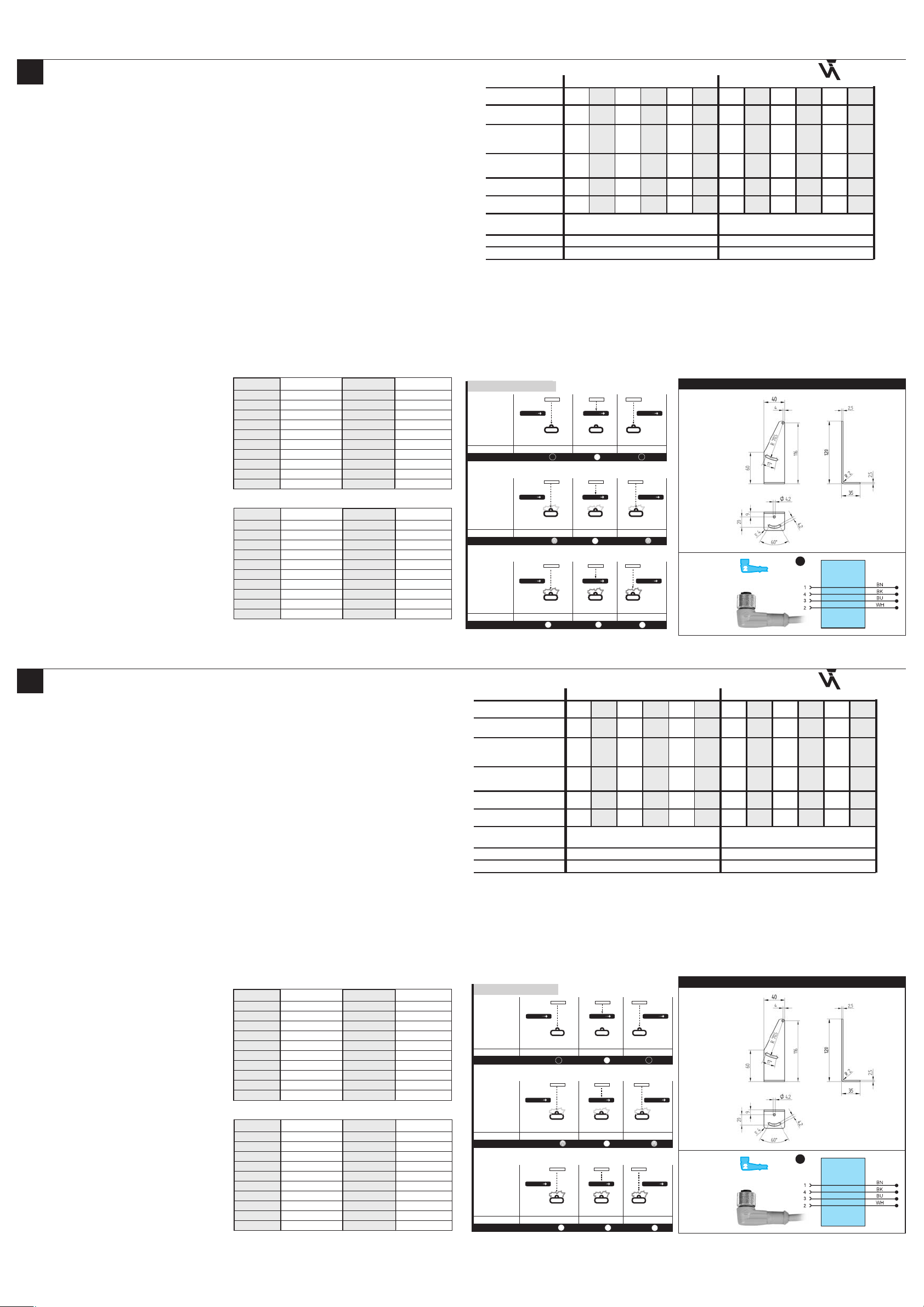
Accessoires
WN
Equerre de fixation
S29-2M
S29-5M
S29-10M
Connecteur
Zone morte
LN 89: Grâce à l'optique monolentille le détecteur n'a pas de zone morte.
LN 40: La distance minimale entre détecteur et réflecteur dépend de la distance de
commutation ajustée et le réflecteur utilisée.
Connecteur
Schéma de raccordement
Référence
Câble
Fréquence d'utilisation
Temps de réponse
Angle d'ouverture
Sortie d'encrassement
Distance de détection
500 Hz
1 ms
11000 mm 5500 mm
1 kHz
0,5 ms
NA
401
NA3
301
PA
201
PA3 PDV PDV3
LN 40 LN 89
x
x
4° 4° 4°
x
101 207 107
4° 4° 4°
xx
xx
x
NA NA3 PA PA3 PDV PDV3
401 301 201 101 207 107
5° 5°
xx
x
5° 5° 5° 5°
x
x
x
xx
Fi . 1
Dia ram Contamination Output / Contamination Warnin
Retro Reflective Barrier no contamination
be innin contamination
advanced contamination
reflector reflector reflector
reflector reflector reflector
reflector reflector reflector
Object
Contamination Output
Si nal LED
Object
Contamination Output
Si nal LED
Object
Contamination Output
Si nal LED
Blind Spot
LN 89 Due to the use of single lens optics, the device has no
blind spot.
LN 40 The minimum clearance between the device and the refector depends
upon the setted switching distance and the used reflector.
Connector
Connection Diagram Nr.
Order Number
Cable
Switching Frequency
Response Time
Beam Angle
Contamination Output
Working Distance
NA NA
401 401
NA3 NA3
301 301
PA PA
201 201
PA3 PA3
101 101
PDV PDV
207 207
PDV3
107
LN 40 LN 89
4° 4° 4° 5° 5°
500 Hz
1 ms
11000 mm 5500 mm
1 kHz
0,5 ms
xx
x
5° 5° 5°4° 4° 4°
xx
x
x
xx
x
x
PDV3
107
5°
xx
xx
x
LN 40
Type Ran e Type Ran e
RQ100BA 0,0811,00mm RE3220BM 0,124,00mm
RE18040BA 0,08 ,00mm RE6210BM 0,153,40mm
RQ84BA 0,089,00mm RR25DM 0,123,00mm
RR84BA 0,089,00mm RR25KP 0,082,00mm
RE9538BA 0,124,00mm RR21KM 0,123,50mm
RE6151BM 0,108,50mm RE6151BH 0,084,50mm
RR50_A 0,085, 0mm RF505 0,124,50mm
RE6040BA 0,088,00mm RF255 0,123,50mm
RE8222BA 0,084,90mm RF508 0,124,50mm
RR34_M 0,124, 0mm RF258 0,123,50mm
LN 89
Type Ran e Type Ran e
RQ100BA 0,005,50mm RE3220BM 0,001,50mm
RE18040BA 0,002, 0mm RE6210BM 0,001,40mm
RQ84BA 0,004,50mm RR25DM 0,001, 0mm
RR84BA 0,004,50mm RR25KP 0,001,10mm
RE9538BA 0,001,40mm RR21KM 0,000,20mm
RE6151BM 0,004,00mm RE6151BH 0,002,20mm
RR50_A 0,003,50mm RF505 0,001,60mm
RE6040BA 0,004,00mm RF255 0,001,30mm
RE8222BA 0,001, 0mm RF508 0,001,60mm
RR34_M 0,002,40mm RF258 0,001,40mm
LN 40
Référence Portée Référence Portée
RQ100BA 0,0811,00mm RE3220BM 0,124,00mm
RE18040BA 0,08 ,00mm RE6210BM 0,153,40mm
RQ84BA 0,089,00mm RR25DM 0,123,00mm
RR84BA 0,089,00mm RR25KP 0,082,00mm
RE9538BA 0,124,00mm RR21KM 0,123,50mm
RE6151BM 0,108,50mm RE6151BH 0,084,50mm
RR50_A 0,085, 0mm RF505 0,124,50mm
RE6040BA 0,088,00mm RF255 0,123,50mm
RE8222BA 0,084,90mm RF508 0,124,50mm
RR34_M 0,124, 0mm RF258 0,123,50mm
LN 89
Référence Portée Référence Portée
RQ100BA 0,005,50mm RE3220BM 0,001,50mm
RE18040BA 0,002, 0mm RE6210BM 0,001,40mm
RQ84BA 0,004,50mm RR25DM 0,001, 0mm
RR84BA 0,004,50mm RR25KP 0,001,10mm
RE9538BA 0,001,40mm RR21KM 0,000,20mm
RE6151BM 0,004,00mm RE6151BH 0,002,20mm
RR50_A 0,003,50mm RF505 0,001,60mm
RE6040BA 0,004,00mm RF255 0,001,30mm
RE8222BA 0,001, 0mm RF508 0,001,60mm
RR34_M 0,002,40mm RF258 0,001,40mm


