manuals.online logo
Brands
  1. Home
  2. •
  3. Brands
  4. •
  5. OPTEX FA
  6. •
  7. Accessories
  8. •
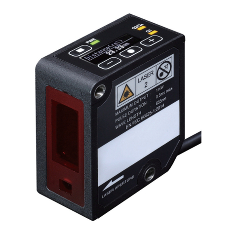
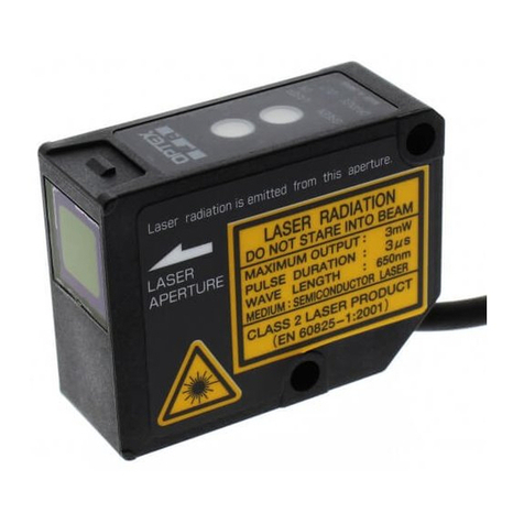
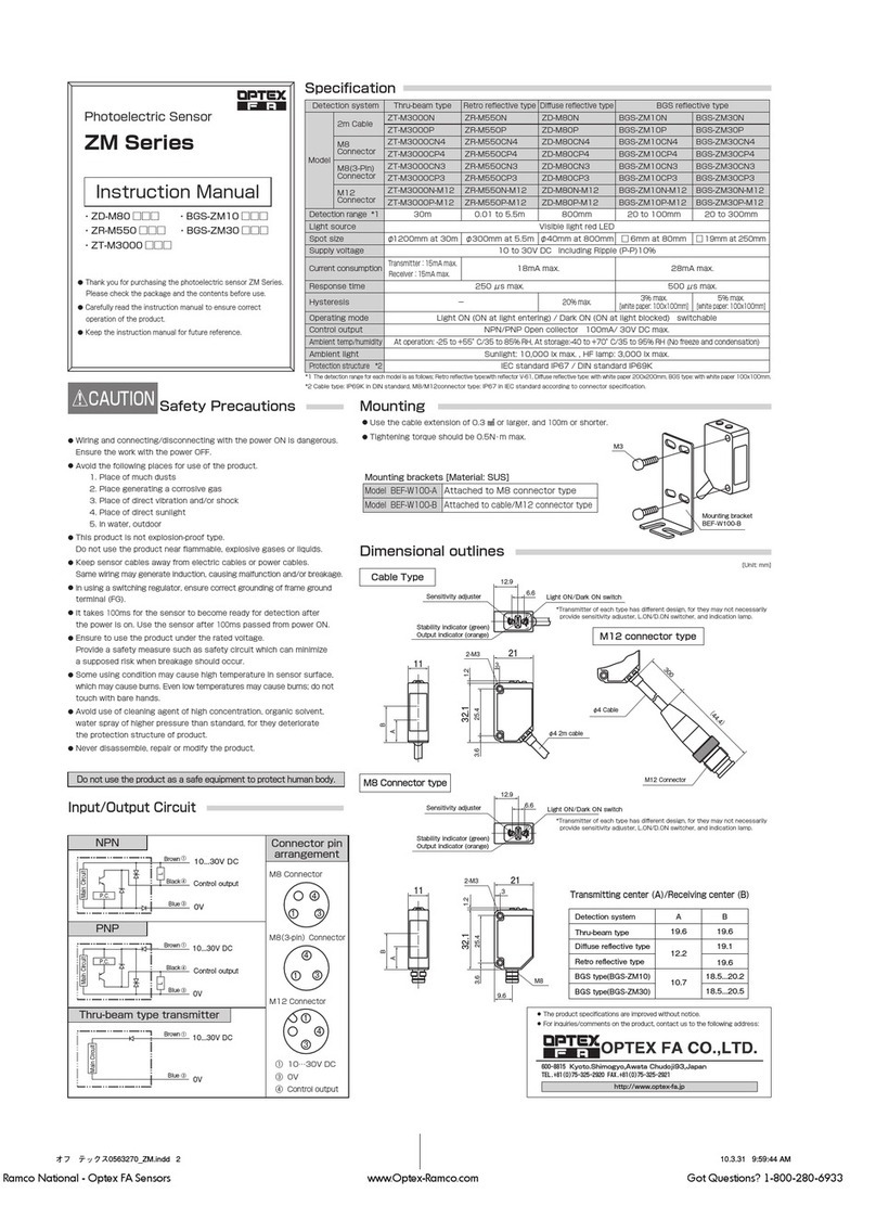
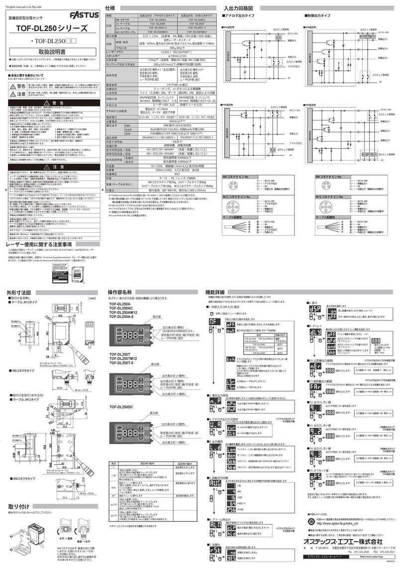
  9. OPTEX FA D Series User manual

OPTEX FA D Series User manual

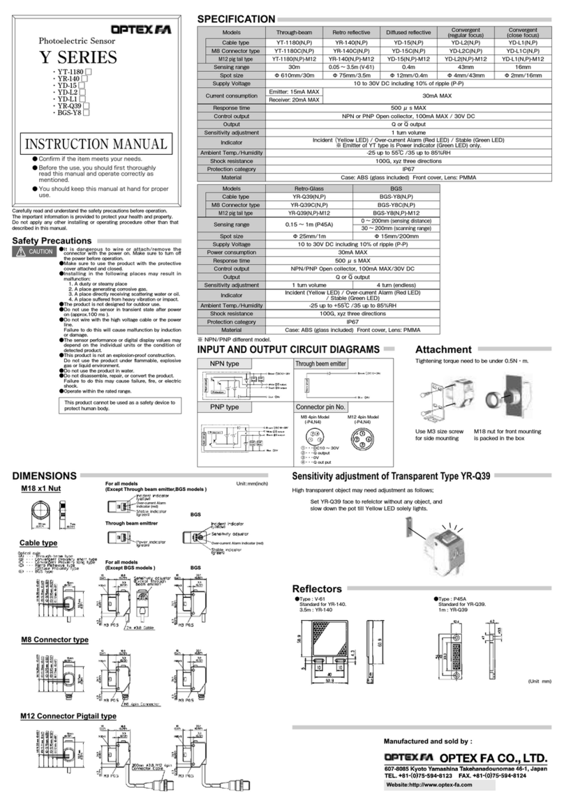
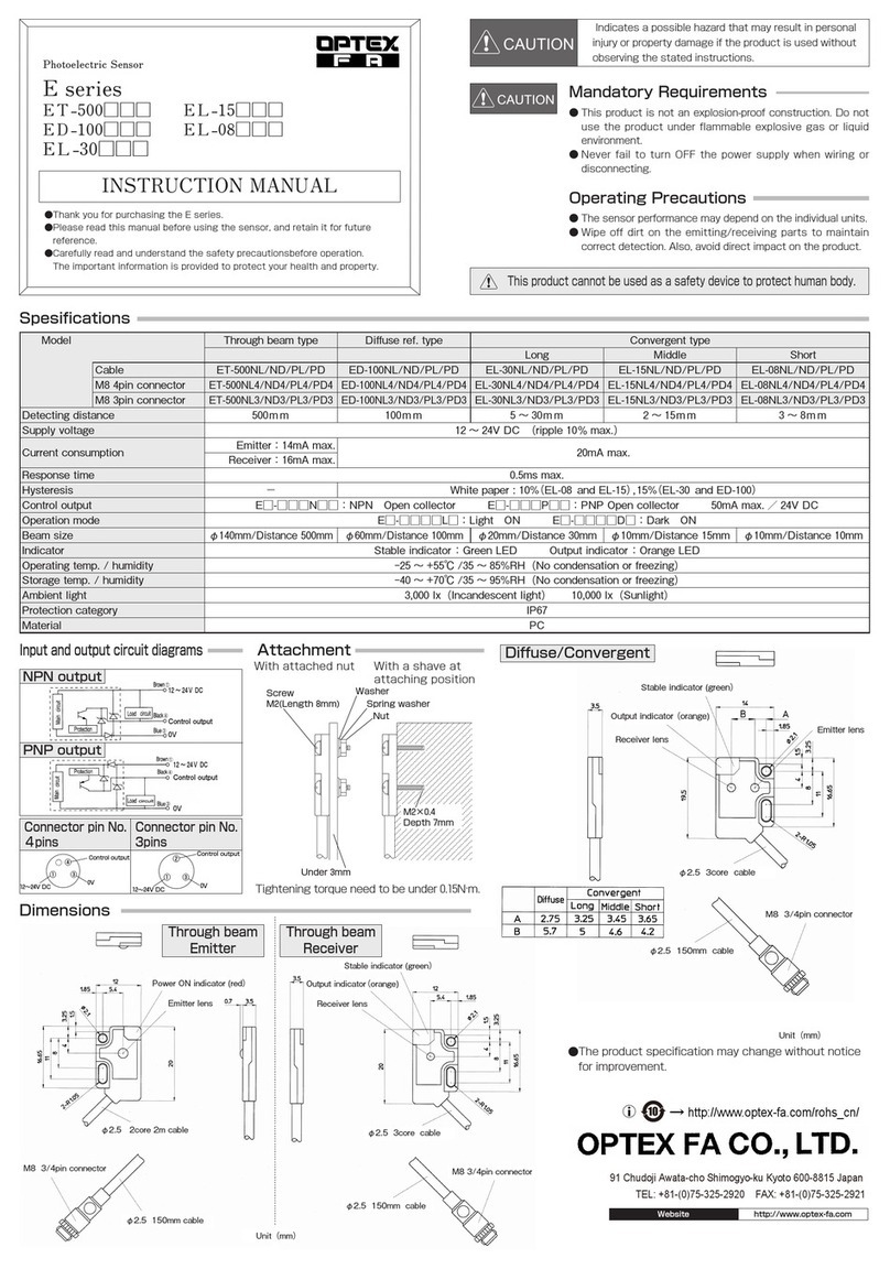
Specifications
Accurate type
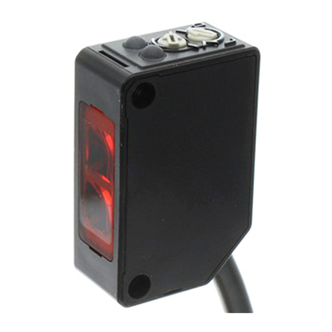
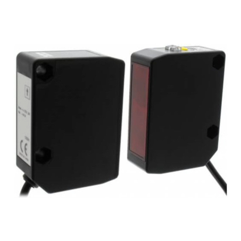
Photoelectric Sensor
BGS-DL10(N,P)-(E) BGS-DL30(N,P)-(E) BGS-DL70(N,P)-(E)
BGS-DL10C (N,P)-(E) BGS-DL30C (N,P)-(E) BGS-DL70C (N,P)-(E)
40~100mm 100~300mm 100~700mm
・DT- 4000□□(E)
・DR- 500□□(E)
・
BGS-DL10
□□
(E)
・BGS-DL30□□(E)
0.2mm/100mm 0.2mm/300mm 0.3mm/400mm
・BGS-DL70□□(E)
Max. 3mW
●
Confirm if the item meets your needs.
●
Before the use, you should first thoroughly read
 this manual and operate correctly as mentioned.
●
You should keep this manual at hand for proper use.
*1  with reflector P250F *2 in the vertical direction of optical axis (theoretical value)
Input/Output circuit design Warnings
NPN
Laser beam
○This item utilizes visible light laser beam and is subject to safety standard
class 2(Ⅱ) of JIS C6802 as well as IEC and FDA regulations.
○Must not stare into laser beam directly or reflection by mirror.
○Must not disassemble.
  Automatic stop function of laser emission is not equipped.
○This product have already been registered at CDRH
(Center for Devices and Radiological Health).
PNP
Parts name Cautions
○Warm-up period (apprx.100 msec.) must be secured.
○Should avoid parallel wiring with high-voltage wire and/ or power line.
Never install in same conduit.
○Avoid dust, oil and water adhesion to sensor forehead to escape
light's insulation and refraction.
   In case of adhesion, wipe with dustless cloth or lens cleaner.
○In case of switching regulator, frame ground (FG) must be grounded.
○Use of controls or adjustments or performance of procedures other
than those specified herein may result in hazardous radiation exposure.
*For connector type only
Dimensions
●
Specifications and equipment are subject to change
without any obligations on the part of manufacture.
●
For more information, questions and comments
regarding products, please contact us below.
Manufactured and sold by :
0534868
0.3mm/5m
Output indicator(Orange LED) , Laser emitter indication (Green LED)
1-turn volume 4-turn volume
Max. 2mW
Emitter   : Laser emitter indication(Green
)
DR-500 (N,P)-(E)
DR-500C (N,P)-(E)
5m *1
BGS type
Longer type
Through beam Retro reflection
type
35mA max.30mA max.
type
DT-4000 (N,P)-(E)
DT-4000C (N,P)-(E)
40 m
40mA max.
Sensitivity adjustment
Control output
Operation mode
Light source
cable type: about 66g / connector type: about 20g
Red Laser diode 650nm  CLASS 2 (Ⅱ)
Light ON / Dark ON Switchable
-10~40℃/ 35~95%
IEC Standard IP67 housing : heat-resistant ABS(antibacterial)lens : PC
Receiver : Output indicator(Orange)
Source pilot lamp(Green)
Cable type
Model
Pin configuration
Response time
Ambient tem/ humid
Protect category/material
Weight
Indicator
NPN/PNP open collector DC30V 100mA max.
DC10 ~30V including 10% ripple (P-P)
0.7ms max.
D SERIES Laser type
INSTRUCTION MANUAL
M8 connector type
Setting range
Supply voltage
Current consumption
Repeat accuracy *2 0.5mm/20m
0.5ms max.
unit: mm
!Must not use this item as safety equipment for the
purpose of human body protection.
Turn the connector as Black Arrow indicates,
otherwise you will damage the connector.
The damage will be unrepairable.
Website : http//www.optex-fa.com
Head office : 600-8815 Kyoto,Shimogyo,Awata Chudoji 93, Japan
TEL +81-(0)75-325-2920 FAX +81-(0)75-325-2921
*The tightening torque should be 0.5N・m or less.

 
→http://www.optex-fa.com/rohs_cn/
OPTEX FA CO.,LTD.
Head office : 91 Chudoji-Awata-cho Shimogyo-ku Kyoto 600-8815 Japan
TEL +81-(0)75-325-2920 FAX +81-(0)75-325-2921
Manufactured and sold by :
Half-turn
connector
Sensitivity setting volume
Laser emitter indication
Output indicator
Light on/Dark on
Controloutput
0V
10~30VDC
③
④
②
①
31
42
Main circuit
LOAD
0V
Controloutput
10~30VDC
Protection circuit
(Blue,③)
(Black,④)
(Brown,①)
Main circuit
0V
Controloutput
10~30VDC
LOAD
Protection circuit
(Blue,③)
(Black,④)
(Brown,①)
0805370
○
Don't bend the cable when the temperature of the cable or atmosphere
is below freezing.
! Mustnotusethisitemassafetyequipmentforthe
purposeofhumanbodyprotection.
Function to set up
Type
Cable type BGS-DL10T(N,P)-(E) BGS-DL25T(N,P)-(E)
Photoelectric Sensor M8 connector type Press or button until appears on digital display panel (about 2 sec.).  After releasing button, function choice is available.
Setting range *1
Supply voltage
Current consumption
・BGS-DL10T□□(E)
・BGS-DL25T□□(E)  BGS Return to "RUN"
BGS/FGS switching FGS
Timer off
Timer
On delay
● Before the use, you should first thoroughly read
this manual and operate correctly as mentioned. Off delay Timer setting
● You should keep this manual at hand for proper use.   0〜999mS (unit:1ms)
*1  100x100mm gray paper (reflectance 90%) *2 in the direction of optical axis One shot   1〜10S (unit: 1s over 999ms)
Input/ Output circuit design Setting range and adjustment
NPN BGS teaching Light ON
① Choose proper setting(between default functions)Operation mode
Dark ON
②
Push and hold button until is shown    
② Push and hold button until          
on digital display panel. (about 2 sec.)     is shown on digital display panel. (about 2 sec.) Auto  Auto : Automatically set up
PNP ③ Present value appears on digital display panel. ③ Present value appears on digital display panel.Sensitivity  Manual: Optionally set up (level 1-20)
Then setting range adjustment is done. Then setting range adjustment is done. Manual         (1:Low → 20:High)
(For ideal setting, press button at the same time.)
        BGS        FGS
Teaching
Parts name
ON
Digital display
OFF (Energy-saving mode)
FGS teaching
① Choose proper setting(between default functions)Default setting
Default setting
Reset
* For connector type only ②
Push and hold button on background until      
② Push and hold button on background until      factory default No
        appears . (about 2 sec.)      appears. (first point: about 2 sec.)
③ Present value appears on digital display panel. ③ After blinking on digital display panel,
Then scanning range adjustment is done.       push button on object. (second point)
Warnings ④ Present value appears on digital display panel.Keylock :Push button at the same time until appears.Push either or button for the confirmation of threshold under keylock.
Laser beam Then scanning range adjustment is done. Same procedure for unlock. ( :unlock)
     ○ This item utilizes visible light laser beam and is subject to safety standard class 2(Ⅱ)
of JIS C6802 as well as IEC and FDA regulations.
      ○ Must not stare into laser beam directly or reflection by mirror.
Dimensions
      ○ Must not disassemble.
Automation stop function of laser emission is not equipped.
Digital indicator
      〇 The numerical display is given in non-linear, and mean just relative values. ● Specifications and equipment are subject to change
     〇 999 or 000 appears in case background or objects are out of scanning range. without any obligations on the part of manufacture.
     〇 The far sensor is positioned to object, the bigger numerical value is.
Cautions ● For more information, questions and comments
     ○ Warm-up period (approx. 100 msec) must be secured.regarding products, please contact us below.
     ○ Should avoid to use sensor at any place where the receiver is influenced
by environmental iluminance directly. Manual setting
     ○ Gaps in indicated values and detection features are possible due to dispersion.
     ○ Use of controls or adjustments or performance of procedures other than the specified herein BGS/FGS(1-point teaching)
     may result in hazardous radiation exposure.① Press or briefly (2 sec. Max). Present value of threshold appears on digital display panel.
○ This product have already been registered at CDRH ② While threshold is blinking, adjust with either or button.(adjustment range:             Push and hold for fast-forwarding)Manufactured and sold by :
(Center for Devices and Radiological Health). ③ Press button, then return to "RUN". Also no button operation for more than 10 sec return to "RUN".
FGS (2-point teaching)
① Press or button briefly (2 sec. Max).
②  Choose (near side) or (far side) by either or button. Then press button.
② While threshold is blinking, adjust with either or button.(adjustment range:             Push and hold for fast-forwarding)
③ Press button, then return to "RUN". Or no button operation for more than 10 sec returns it to "RUN".
0535393
NPN/PNP open collector DC30V 100mA max.
Indicator Output indicator (Orange LED),  Laser emitter indication(Green LED)
Pin configuration
Operation mode
Scanning range adjustment
Ambient temp/ humid
Protection category/ material
● Confirm if the item meets your needs.
Digital indicator 7 segment, 3 digits Red LED (function indicator, 0〜999 distance index)
Response time 1.5ms max.(fixed sensitivity)
Light source Red laser diode (wave:650nm  Max. 1mW  class2)
Repeat accuracy *2
Control output
Off delay / On delay / One shot delay (1msec increment :0-999msec, 1sec increment for 1-10sec)
0.3mm/100mm
Accurate type Longer type
BGS-DL10TC(N,P)-(E) BGS-DL25TC(N,P)-(E)
40〜100mm 100〜250mm
DC10 〜 30V including 10% ripple (P-P)
40mA max. (12V) , 27mA max (24V)
D SERIES Laser type
0.4mm/200mm
Specification
Weight
Light ON/ Dark ON selectable
Teaching /Manual setting
-10〜40℃ / 35〜85%
IEC standard IP67 housing : heat-resistant ABS(antibacterial)   lens : PC   button : TEEE
cable type: about 68g / connector type: about 20g
Timer
!Must not use this item as safety equipment for the
purpose of human body protection.
Unit: mm
1Pt :1-point teaching
2Pt : 2-point teaching
PoS : Positioning teaching
1-point teaching positioning teaching
sensor
threshold
background
Threshold should be set closer than background.
threshold
Threshold should be set on the
border of object.
1-point teaching 2-point teaching
sensor
background
scanning range
threshold
near side
threshold
far side(fixed)
Set detecting range within the shaded
area shown above.
sensor
threshold
near side
threshold
far side
background scanning
range
object
Set detecting range within the shaded
area shown above.
BGS:Background suppression
FGS:Foreground suppression
BGS/FGS : BGS
Timer : OFF
Operation mode : Light ON
Sensitivity : Auto
Scanning range adjustment : 1-point
teaching
Digital display : ON
object
sensor
BGS : 50〜950
FGS : 50〜930
Near : 50〜930
Far : 70〜950
Setting range
adjustment
Setting range adjustment
foreside
backside
Teach /
Enter Turn the connector as Black Arrow indicates,
otherwise you will damage the connector. The
damage will be unrepairable.
INSTRUCTION MANUAL
607-8085 Kyoto, Yamashina,Takehanadonomaecho 46-1, JAPAN
Tel : +81-(0)75-594-8123
Fax : +81-(0)75-594-8124
Website : http//www.optex-fa.com
laser emitter indication
output indicator
digital display panel

Other OPTEX FA Accessories manuals

OPTEX FA Z Series User manual

OPTEX FA

OPTEX FA Z Series User manual

OPTEX FA D Series User manual

OPTEX FA

OPTEX FA D Series User manual

OPTEX FA FASTUS TOF-DL250 Series User manual

OPTEX FA

OPTEX FA FASTUS TOF-DL250 Series User manual

OPTEX FA Fastus CD2H Series User manual

OPTEX FA

OPTEX FA Fastus CD2H Series User manual

OPTEX FA CD33-L Series User manual

OPTEX FA

OPTEX FA CD33-L Series User manual

OPTEX FA Y Series User manual

OPTEX FA

OPTEX FA Y Series User manual

OPTEX FA E Series User manual

OPTEX FA

OPTEX FA E Series User manual

OPTEX FA CD4 Series User manual

OPTEX FA

OPTEX FA CD4 Series User manual

OPTEX FA CVS1-RA Series User manual

OPTEX FA

OPTEX FA CVS1-RA Series User manual

OPTEX FA V Series User manual

OPTEX FA

OPTEX FA V Series User manual

OPTEX FA MVS Series User manual

OPTEX FA

OPTEX FA MVS Series User manual

OPTEX FA CVS4-*R Series User manual

OPTEX FA

OPTEX FA CVS4-*R Series User manual

OPTEX FA CD5 Series User manual

OPTEX FA

OPTEX FA CD5 Series User manual

OPTEX FA CVS3 User manual

OPTEX FA

OPTEX FA CVS3 User manual

OPTEX FA CD5 Series User manual

OPTEX FA

OPTEX FA CD5 Series User manual

OPTEX FA CVS2-RA Series User manual

OPTEX FA

OPTEX FA CVS2-RA Series User manual

OPTEX FA DSR-800 User manual

OPTEX FA

OPTEX FA DSR-800 User manual

OPTEX FA ZM Series User manual

OPTEX FA

OPTEX FA ZM Series User manual

OPTEX FA CD33 SERIES User manual

OPTEX FA

OPTEX FA CD33 SERIES User manual

OPTEX FA V2 Series User manual

OPTEX FA

OPTEX FA V2 Series User manual

OPTEX FA FASTUS CDX-L15A User manual

OPTEX FA

OPTEX FA FASTUS CDX-L15A User manual

OPTEX FA CD5 Series User manual

OPTEX FA

OPTEX FA CD5 Series User manual

Popular Accessories manuals by other brands

Integrated Visual Data Technology Inc. ED3-Zebra SkidWeigh Plus Series Installation & Calibration Manual

Integrated Visual Data Technology Inc.

Integrated Visual Data Technology Inc. ED3-Zebra SkidWeigh Plus Series Installation & Calibration Manual

Gastro-Cool Retro Slimline GCGD175 Instructions for use

Gastro-Cool

Gastro-Cool Retro Slimline GCGD175 Instructions for use

Hubbell NX Distributed Intelligence NXSMP-LMI Installation and operation instructions

Hubbell

Hubbell NX Distributed Intelligence NXSMP-LMI Installation and operation instructions

Midlite M2PJCTVW5 manual

Midlite

Midlite M2PJCTVW5 manual

ipf electronic UT189020 manual

ipf electronic

ipf electronic UT189020 manual

Pascal Box Pascal Box user guide

Pascal Box

Pascal Box Pascal Box user guide

Solight PP120USBCW installation manual

Solight

Solight PP120USBCW installation manual

LevelOne AVIL01W quick start guide

LevelOne

LevelOne AVIL01W quick start guide

Banner WORLD-BEAM QS18 Expert Series instruction manual

Banner

Banner WORLD-BEAM QS18 Expert Series instruction manual

Cub VS-60U024 Series manual

Cub

Cub VS-60U024 Series manual

Panasonic Light Emitting Diodes LNJ214R8ARA Specifications

Panasonic

Panasonic Light Emitting Diodes LNJ214R8ARA Specifications

FUTABA GY701 quick start guide

FUTABA

FUTABA GY701 quick start guide

Hupfer SGR operating instructions

Hupfer

Hupfer SGR operating instructions

Schwaiger ZHS10 manual

Schwaiger

Schwaiger ZHS10 manual

Omron E8F2 - manual

Omron

Omron E8F2 - manual

FixPosition NAV-RTK Operation manual

FixPosition

FixPosition NAV-RTK Operation manual

Oregon Scientific WGR800X user manual

Oregon Scientific

Oregon Scientific WGR800X user manual

PCB Piezotronics 426A13 Installation and operating manual

PCB Piezotronics

PCB Piezotronics 426A13 Installation and operating manual

manuals.online logo
manuals.online logoBrands
  • About & Mission
  • Contact us
  • Privacy Policy
  • Terms and Conditions

Copyright 2025 Manuals.Online. All Rights Reserved.