Warning Indication (OA-603 Sensor head)
TROUBLE SHOOTING
Advise the building owner/operator of the following items
1. When turning the power on, stay clear of detection area for a minimum of 10 seconds then walk test detection
area to ensure proper operation.
2. Always keep the detection window clean. If dirty, wipe the window with a damp cloth ( Do not use any cleaner or solvent ).
3. Do not wash the sensor with water.
4. Do not disassemble, rebuild or repair the sensor yourself; otherwise electric shock may occur.
5. Contact your installer or the sales engineer if you want to change the settings.
6. Do not place an object that moves or emits light in the detection area.(ex. Plant, illumination etc..)
7. Do not paint the Detection Window.
“Take Care of Environment”. This manual uses recycled paper.
OPTEX CO.,LTD.
(ISO 9001 Certified by LRQA)
5-8-12 ogoto Otsu,
520-0101 Japan
TEL.: +81 (0)77-579-8700
FAX : +81 (0)77-579-7030
WEBSITE: www.optex.co.jp
Secumatic b.v.
Tiber 2 . 2491 DH The Hague , P.O. Box 24009
2490 AA The Hague The Netherlands
TEL.: +31 (0)70 419 41 00
FAX : +31 (0)70 317 73 21
WEBSITE: www.secumatic.nl
Optex Technologies, Inc.
3882 Del Amo Blvd., Suite 604,
Torrance, CA 90503-2184, USA
TEL: +1 (310) 214-8644
FAX: +1 (310) 214-8655
TOLL-FREE: +1 (800) 877-6656
WEBSITE: www.optexentrances.com
Contact your installer or the sales engineer if:
- you need to change the settings or replace the sensor.
- the trouble still persists after checking and remedying as described above.
1-8
Symptom Possible cause Solution
OC-904C no LED indication
OC-904C LED double orange flashing & no LED
indication on OA-603
CANNOT INITIATE SETUP
WILL NOT COMPLETE INITIAL SETUP
Improper power supply Correct power problem
Bad connection on Orange and Brown wires of OC-904 Repair bad connection
Bad connection at OC-904 Reseat 4 pin connector from Loop assy to OC-904
Bad connection from loop assy
To OA-603 sensor head
Reseat 4 pin connector from loop assy to OA- 603 sensor head
Bad connection with 7" pass thru cable Reseat connection of 7" cable to both OA-603 sensor heads
Bad 7" cable Replace as necessary
OC-904 LED double orange flashing & erratic LED
on OA-603 sensors
Switches 7 & 8 of left dipswitches on OA-603 sensors set wrong Correct dipswitch settings see pg 1-2
OC-904 dipswitches set wrong Check Connection Matrix for proper dipswitch settings
Poor or improper connection of yellow wires from OC-904 to door control Check Connection Matrix for proper connection of yellow wires
Improper voltage on red & black wire of OC-904 Ensure positive voltage on red wire at hold open and 0 voltage
at closed position
INTERMITENT RECYCLE (ghosting) OR INTERMITENT STALLING After initial setup door ghosts several times on first activation Happens on 15% of installations
If stops after first activation, system is OK
OA-603 sensor head not mounted flush on door Head may be resting on top of loop mounting bracket
Reposition head flush on panel
Improper threshold or swing area angle adjustment Set threshold and swing area angles at +5 degrees (deep)
Improper voltage on red & black wire of OC-904 Ensure positive voltage on red wire at hold open and 0 voltage
at closed position
Stalling caused by traffic just outside of swing path or objects
near guide rails
Set switch 6 on left bank dipswitch of OA-603 on/up (shallow)
Note: moving the dipswitch will initiate a setup
Area width dipswitches set wrong
(right bank dipswitches on OA-603)
Verify proper settings (page 1-2)
Inconsistent data from position sensor/loop assy Postion the loop assy so loop center coupler does not rest on
door at any point of door travel
NO ACTIVATION AND/OR NO REACTIVATION ON CLOSING CYCLE OC-904 yellow wires poor or improper connection to door control
or on/off/hold switch
Verify proper connection and output of yellow wires.
(see Elite Connection Matrix)
OC-904 dipswitches set improperly Verify proper settings(see Elite Connection Matrix)
On knowing act applications poor or improper connection of
purple wires from OC-904 to activation device
Verify good and proper connection (see OC-904 install manual)
NO SAFETY ON SWING SIDE AT FULL
CLOSED
OA -603 sensor detects (solid or flashing red LED)
but door opens anyway
Poor or improper connection of Blue wires from OC-904 to door
control
Verify good and proper connection of blue wires
(see Elite Connection matrix)
OC-904 dipswitches set improperly Verify proper settings (see Elite Connection Matrix)
OA-603 no detection (solid green LED) Area width dipswitches set wrong
(right bank dipswitches on OA-603)
Verify proper settings (page 1-2)
NO STALL ON SWING SIDE WHILE
DOOR IS OPENING
OA -603 sensor detects (solid or flashing red LED)
but door does not slow or stop
Poor or improper connection of green wires from OC-904 to door
control
Verify good and proper connection of Green wires
(see Elite Connection matrix)
OC-904 dipswitches set improperly Verify proper settings (see Elite Connection Matrix)
OA-603 no detection (solid green LED) Area width dipswitches set wrong
(right bank dipswitches on OA-603)
Verify proper settings (page 1-2)
DOOR REMAINS OPEN OC-904 dipswitches set improperly Verify proper settings (see Elite Connection Matrix)
On knowing act applications poor or improper connection of
purple wires from OC-904 to activation device
Verify good and proper connection (see OC-904 install manual)
Improper wiring of door equipment on/off/hold switch Verify proper wiring of on/off/hold switch
Moving dipswitch on OA-603 does not
result in OA-603 LED fast flash yellow.
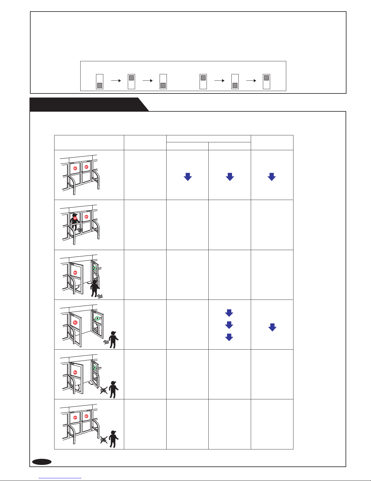
Mode Self Monitoring Function Life cycle Notification Signal Saturation Communication Error Setting Error
Operation Indicator
Explanation
Fast Green Blinking Twice Green Blinking Slow Green Blinking
The sensor is reaching the
end of its life cycle.The relay is reaching the
end of its life cycle.
Either the mounting position is too
low or the detection area includes
the wall or another object.
OA-603 threshold angle may be
set to less than +5 degrees deep.
Refer to "ADJUSTMENT".
The sensor cable is connected,
but unstable communication.
A sensor cable may be
disconnected or OA-603 mode
switches 7 & 8 may be set wrong.
Refer to "ADJUSTMENT"
When all the area width switches
are inactive.
Refer to "ADJUSTMENT".
Fast Orange Blinking
Twice Orange Blinking