Optex OA-203C User manual

221 ( 8 11/16"
)
125 (4 15/16"
)
3
6 ( 1 7/16"
)
6
3 ( 2 1/2"
)
29.9 ( 1 3/16" )
43 ( 1 11/16" )
ON
(3.5 x 2)(3.5 x 2)
AREA WIDTH
A
ADJUSTMENT
S
LEFT
ELIMINAT
RI
G
H
T
ELIMINAT
180sec
.
12
DEEP
RIGHT
SHALLOW
12
1
5se
LEFT
H
FRE
Q
UENC
Y
SWIT
CH
S
N
O
W M
O
D
E
1212
2
sec
5726130
ADJUSTMENT
SCREW
M
S
ENSITIVIT
Y
S
WIT
CH
TIMER
ADJUSTMEN
T
GREY : POWER 12to30V AC/DC
WHITE : OUTPUT COM.
YELLOW : OUTPUT N.O.
GREEN : OUTPUT N.C.
CURRENT DRAW :XXXmA Max
OUTPUT : Form C 50V0.3A Max
(RESISTANCE LOAD)
OPERATION INDICATOR
GREEN : STAND-BY
RED : 1st ROW DETECTION
ORANGE : OTHER AREADETECTION
4R
OW
3
R
O
W
2R
OW
1ROW
7
8
78
7
8
7
8
(1 x 4)(1 x 4)
L
L
MANUFACTURER’S STATEMENT
OA-203C
Read this Operation Manual carefully before use, to ensure proper operation of this Optex sensor.
Failure to read this Operation Manual may cause improper sensor operation and may result in serious injury or death.
This product is a non-contact activating s itch intended for mounting on the header of an automatic door.
Do not use it for any other applications; other ise proper operation and safety cannot be guaranteed.
Cautions:
1. Follo the instructions (especially Note ) in this Operation Manual hen installing and adjusting the sensor.
2. When setting the sensor's area pattern, make sure there is no traffic around the installation site.
3. Before turning the po er on, check the iring to prevent damage or malfunction of equipment that is connected to the sensor.
4. Do not ash, disassemble, rebuild or repair the sensor by yourself; other ise it may cause electric shock or breakdo n of the
sensor.
5. Only use the sensor as specified in the supplied instructions.
6. Be sure to install the sensor in accordance ith the local la s and standards of your country.
7. Before leaving the jobsite, be sure that this sensor is operating properly and instruct the building o ner/operator on proper
operation of the door and this sensor.
Model
Cover color type
Mounting Height
Detection Area
Detection Method
Detection Angle
Adjustments
Detection Width
Adjustments
Po er Supply
Current Dra
Operation Indicator
*The specifications herein are subject to change ithout
prior notice due to improvements.
: OA-203C
: Silver / Black / White
: 3.0m (9’10”) Max.
: See “Detection Area”
: Active Infrared Reflection Method
: ±4° adjustable by 1° every one click
(Deep / Shallo )
: ±7° adjustable by 3.5° every one click
(Right / Left)
: 12 to 30V AC / DC
: 160mA Max. (at 12V AC)
: Green / Stand-by
Red / 1st Ro Detection Active
Orange / Other Ro Detection Active
SPECIFICATIONS
Output
Relay Hold Time
Response Time
Operating Temperature
Weight
Accessories
: “Form C” relay 50V 0.3A Max.
(Resistance Load)
: 0.5 sec.
: < 0.3 sec.
: -20°C to +55°C (-4°F to +131°F)
: 200g (7.1oz)
: 1 Cable 3m (9’10”)
2 Mounting Scre s
1 Operation Manual
1 Mounting Template
1 Area Adjustment Tool
OUTER DIMENSIONS
1 : Connector
2 : Sensitivity S itch
3 : Mounting holes
4 : Dips itches
5 : Area Adjustment Tool
6 : Area Adjustment Scre
7 : Width Adjustment Shutters
8 : Operation Indicator
9 : Detection Windo
mm (inch)

5
4
3
2
INSTALLATION
2. Drill t o mounting holes (ø 3.4mm or 1/8”).
3. To carry through the ire to the header, drill a iring
hole (ø 8mm or 5/16”).
4. After drilling the holes, remove the Mounting Template.
Note
Be sure that the mounting height is ithin the value of
those in "SPECIFICATION."
1Remove the cover and attach the sensor ith scre s.
Plug the Connector for the sensor to that for the cable.
Supply po er to the sensor. Adjust the detection area
and set the various S itches. (See “ADJUSTMENT.”)
Note
Make sure that you connect the cable correctly to the
Control Unit of the door before turning the po er on.
1. Put back the cover on the sensor.
2. If iring is to be exposed, break the Knockout.
Mounting
Template
3m
Max.
Grey Po er Supply
Grey 12 to 30V AC / DC
White : COM.
Yello : N.O.
Green : N.C.
Note
Connect the cable hen main po er is turned off.
Note
When passing through the cable to the hole, make sure not
to tear shield: other ise it may cause electric shock or
breakdo n of sensor.
6
Note
Do not use the sensor ithout the cover. Install the sensor
indoors or use the rain-cover (Optional), hen using the Cable
Knockout, other ise it may cause electric shock or breakdo n
of sensor.
Knockout
1. Affix the Mounting Template to the mounting surface.
The cable is arranged to connect to the door
controller properly as sho n belo .
A 2.00 2.20 2.50 2.70 3.00
B 0.28 0.31 0.35 0.38 0.41
C 0.68 0.75 0.85 0.92 1.02
D 1.18 1.30 1.48 1.59 1.77
E 2.10 2.30 2.60 2.80 3.10
F 0.16 0.18 0.20 0.22 0.25
A 6’ 6 3/4” 7’ 2 5/8” 8’ 2 7/16” 8’ 10 5/16” 9’ 10 1/8”
B 11” 1’ 3/16” 1’ 1 3/4” 1’ 2 15/16” 1’ 4 9/16”
C 2’ 2 3/4” 2’ 5 1/2” 2’ 9 9/16” 3’ 1/4” 3’ 4 3/16”
D 3’ 10 7/16” 4’ 3 3/16” 4’ 10 1/4” 5’ 2 5/8” 5’ 9 11/16”
E 6’ 10 11/16 7’ 6 9/16” 8’ 6 3/8” 9’ 2 1/4” 10’ 2 1/16”
F 6 5/16” 7 1/16” 7 7/8” 8 11/16” 9 13/16”
*The values of the chart blo is of the Emitting Spots, but not of
the Detection Area.
The actual Detection Area may become smaller depending on
the ambiance light and the colour / material of object and the
floor as ell as the entry speed of object.
[ m ]
[ feet , inch ]
B
CD
A
F
E
Detection Areas are sho n in the figure belo .
After adjustment, turn the po er off and on again, be sure to
alk-test all of detection areas.
1st Ro
2nd Ro
3rd Ro
4th Ro
: Detection Area
: Emitting Spot
Presence Detection
Motion Detection
Provided Detection Ro type 1st 2nd 3rd 4th
DETECTION AREA

5 6 56
Immunity
56
snow
mode
56
normal
heavy
snow
mode
3 4 3 4 3 4 34
Position
1
Position
2
Position
3
Position
4
3
2
01.0m2.0m 1.0m
18
27
36
45
01.0m 1.0m 2.0m
3.0m
2.8m
2.6m
2.4m
2.2m
2.0m
1.0m
3.0m
2.8m
2.6m
2.4m
2.2m
2.0m
1.0m
18
27
36
45
01.0m 1.0m
3.0m
2.8m
2.6m
2.4m
2.2m
2.0m
1.0m
1
234
8
7
6
5
Adjusting the Pattern Width
Pattern hen changed 7
to Right
Pattern hen changed 7
to Left
Pattern hen Standard
1
ADJUSTMENT
Note Setting the pattern for exact door opening may give a slo response to side approaching traffic.
: Erasable
Area
: Erasable
Area
: Erasable
Area
Setting the Width
adjustment shutters
Adjusting the Width Angle
Left or Right : bet een 0 to 7
(3.5 per click)
to Left
Opens
All Areas
Eliminate
12787 812
Eliminate Eliminate
to Right
Setting the Ro ith the
Dips itch 7 & 8.
Pattern hen changed 4
to Deep (outside).
Pattern hen changed -4
to Shallo (inside).
Pattern hen Standard
0m
1.0m2.0m
1.0m
2.0m
2.2m
2.4m
2.6m
2.8m
3.0m 0m
1.0m2.0m
1.0m
2.0m
2.2m
2.4m
2.6m
2.8m
3.0m 0m
1.0m2.0m
1.0m
2.0m
2.2m
2.4m
2.6m
2.8m
3.0m
0m
1.0m2.0m
1.0m
2.0m
2.2m
2.4m
2.6m
2.8m
3.0m
Adjusting the Pattern Depth
78
4ROW 3ROW 2ROW 1ROW
78 78 78
: Erasable
Area
: Erasable
Area
: Erasable
Area
1st
2nd3rd4th 1st2nd3rd4th
1st2nd3rd4th
1 2 12
15sec.
12
180sec.
1 2
2sec.
1 2 3 4 5 6 7 8
ON
ON
LMHL M H
Setting of Sensitivity S itch and Dips itches
Sensitivity S itch Dips itches
Setting the Sensitivity
Normally set to “M.”
“H” increases the sensitivity and “L” lo ers the sensitivity.
Setting the Presence timer
1st Ro and 2nd Ro from
door provide the presence detection.
(1) Select the presence detection time.
(2) Turn the po er off and on again. Other ise it may
leave door open for the duration of the presence time
set.
(3) After making sure that the door closes, ait for 10
seconds before entering the detection area to set the
Presence timer.
Setting the Frequency Function
(Interference Prevention)
Four different frequencies can be
set by adjusting the Dips itch 3
and 4.
Note When t o or more sensors are installed close to each
other, it is possible that they interfere. When that happens,
change the Frequency.
Setting the Sno mode
Set the Dips itch5 and 6 to sno
mode , if the sensor is used in a
region ith sno or a lot of insects.
Adjusting the Depth
Angle bet een -4 to 4
(1 per click).
Shallo
Note Set the pattern for actual traffic. It may cause slo activation for the traffic from the front, hen the Ro is eliminated.
Depth

TROUBLESHOOTING
Note The door may open once after the po er is s itched on.
Inform the follo ing items to the building
o ner/operator
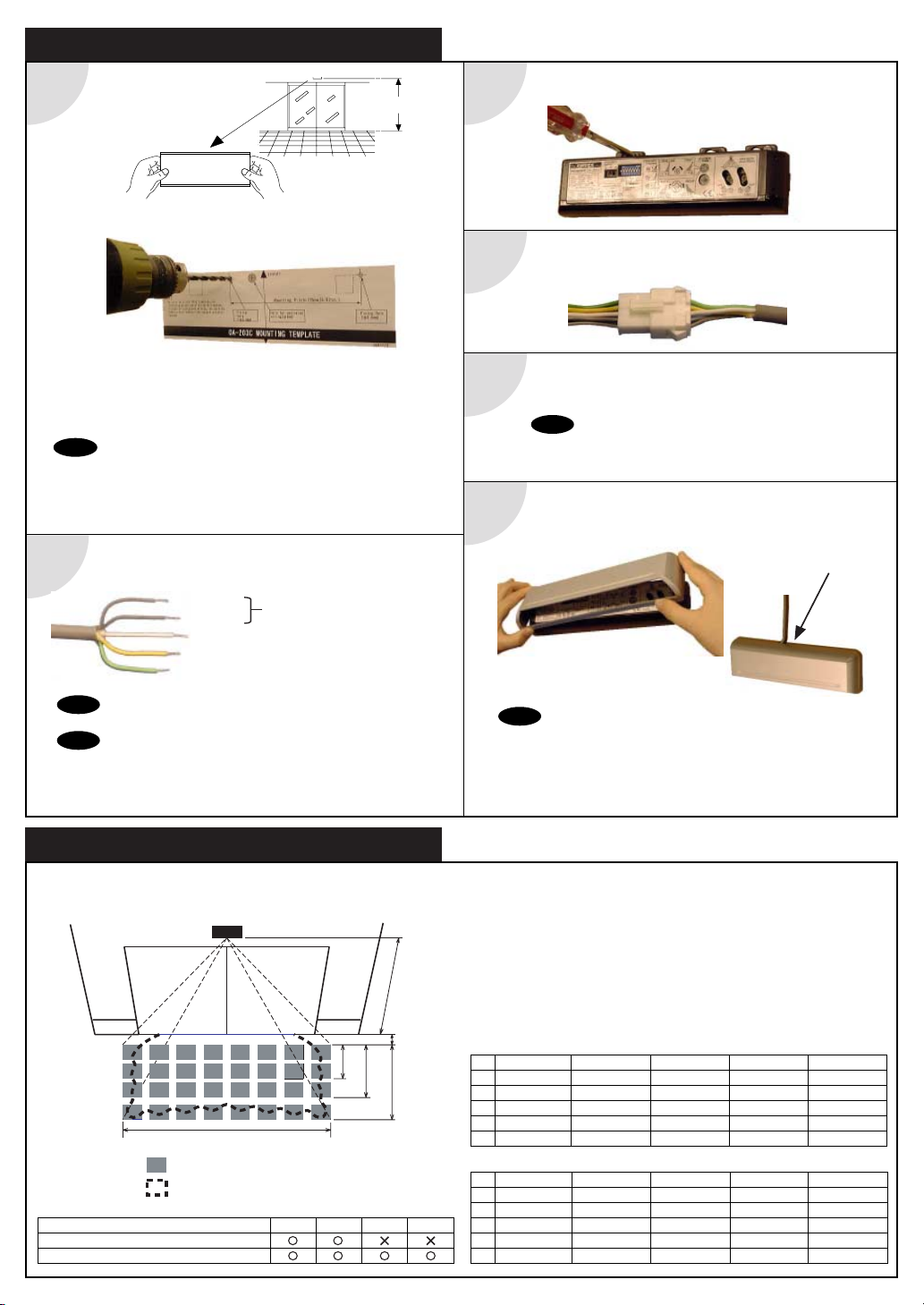
1. When turning the po er on, al ays alk-test the sensor pattern to ensure proper operation.
2. Al ays keep the detection indo clean. If dirty, ipe the indo ith a damp cloth. (Do not use any cleaner or solvent.)
3. Do not ash the sensor ith ater.
4. Do not disassemble, rebuild or repair the sensor yourself; other ise electric shock may occur.
5. Contact your installer or the sales engineer if you ant to change the settings.
6. Do not place an object that moves or emits light in the detection area. (Ex. Plant, illumination, etc.)
7. Do not paint the Detection Windo .
Contact your installer or the sales engineer if:
- you need to change the settings or replace the sensor.
- the trouble still persists after checking and remedying as described above.
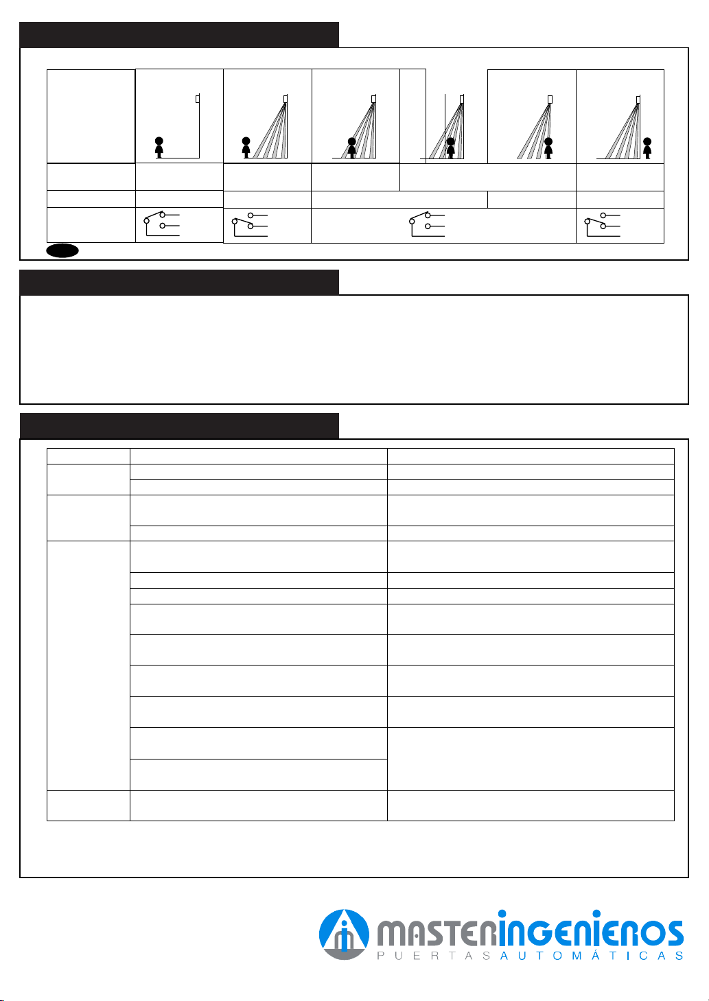
Entry motion
Po er OFF Outside the
Detection area
Entry into 3rd or
4th Ro
(image)
Sensor status Po er OFF Stand-by Motion
Detection Active
Entry into 2nd Ro Entry into 1st
Ro
Outside the
Detection area
Motion or Presence
Detection Active Stand-by
Orange Red Green
Yello
Green
White
Output
Operation indicator GreenOFF
Yello
Green
White
Yello
Green
White
Yello
Green
White
Does not
operate
Dose not
operate
consistently
Operates by
itself
(Ghosting)
Po er supply is not adequate.
Connection Failure.
Dirty detection indo .
Sensitivity is Lo .
There is an object that moves or emits light in
the detection area. (Ex. plant, illumination, etc.)
Vibration of the header.
Sensitivity is high.
Waterdrops on detection indo .
Detection area has interfered the area of
another sensor.
The detection 1st ro spots are overlapping ith
the door / header.
Door stay
open or closed
There is an reflected object in the detection area.
Solar light reflects.
Presence timer is Infinity. There as an abrupt
condition change in the detection area.
Adjust to stated voltage.
Check the iring and the connector.
Wipe the detection indo ith a damp cloth. (Do not
use any cleaner or solvent.)
Set the Sensitivity S itch “H.”
Set the Sensitivity S itch “L.”
Remove the object.
Remove the object.
Secure the header. Or set the Sensitivity S itch “L.”
Install in a place keeping the aterdrops off. OR
use a rain-cover (Optional).
Set the different frequency position each other.
Adjust the detection area to deep (outside).
Turn the po er off and on again.
Trouble Possible Cause Solution
CHECKING
Check the operation according to the chart belo .
There as a puddle left by rain or sno .
The floor has gotten et.
The exhaust of the car and the fog penetrate into
the detection area.
This sensor is equipped ith the anti-malfunction.
Ho ever, pay attention hen installing as malfunction
may occur under the left conditions.
Other Optex Accessories manuals

Optex
Optex OVS-01GT User manual

Optex
Optex Fiber SenSys Terrain Defender TD 100 User manual

Optex
Optex OA-FLEX AIR T User manual

Optex
Optex TS-1000-D User manual

Optex
Optex i-oneX T User manual

Optex
Optex GEN-DC User manual

Optex
Optex OA-4500S(E) User manual

Optex
Optex OA-AXIS T User manual

Optex
Optex ProSafe OA-Presence User manual

Optex
Optex OAM-DUAL T User manual

Optex
Optex OA-4500S User manual

Optex
Optex AX-250PLUS User manual

Optex
Optex SIP-3020/5 User manual

Optex
Optex OA-FLEX LITE User manual

Optex
Optex Prosafe OA-1V User manual

Optex
Optex RXC-DT-X5 User manual

Optex
Optex X-ZONE User manual

Optex
Optex OA AXIS T User manual

Optex
Optex Pro Swing Elite ST User manual

Optex
Optex V2 Series User manual