manuals.online logo
Brands
  1. Home
  2. •
  3. Brands
  4. •
  5. Optex
  6. •
  7. Accessories
  8. •
  9. Optex OA-FLEX LITE User manual

Optex OA-FLEX LITE User manual

OA-FLEX LITE
ENGLISH
5933110 NOV 2022
Manufacturer's statement
Read this operation manual carefully before use to ensure proper operation of this product.
Failure to read this operation manual may cause improper operation and may result in serious injury or death of a person.
The meanings of the symbols are as follows.
1. This product is a non-contact switch intended for header mount or wall mount for use on an automatic
sliding door. Do not use for any other applications.
2. When setting the sensor's detection area, make sure that there is no traffic around the installation site.
3. Before turning the power ON, check the wiring to prevent damage or malfunction of equipment
connected to the product.
4. Only use the product as specified in the operation manual provided.
5. Be sure to install and adjust the sensor in accordance with the local laws and standards of the country
in which the product is installed.
6. Before leaving the installation site make sure that the product is operating properly and instruct the
building owner/operator on proper operation of the door and the product.
7. The product settings can only be changed by an installer or service engineer.
When changed, the changed settings and the date shall be registered in the maintenance logbook
accompanying the door.
NOTE
Failure to follow the instructions that accompany this indication and improper handling
may result in serious injury or death.
WARNING
Failure to follow the instructions that accompany this indication and improper handling
may result in injury and/or damage to property.
CAUTION
Pay special attention to sections with this symbol.
NOTE
Do not wash, disassemble,
rebuild or repair the sensor,
otherwise it may cause electric
shock or breakdown of the
equipment.
Danger of electric shock
WARNING
The following conditions are not suitable for sensor installation.
Fog,
Exhaust Wet Vibration Objects Reflection
Specifications
1000 ms 1000 ms
Signal saturation
Sensitivity too low
Slow Green blinking
Fast Green blinking
Operation indicator table
Status Operation indicator color
Stand-by Green
3rd - 5th row detection Orange
2nd row detection Red
1st row detection Red blinking
*1 :
When using this sensor, the sensor has to be connected to a door system which has the SELV circuit.
*2 : Overcurrent protection with less than 2A.
The specifications herein are subject to change without prior notice due to improvements.
NOTE
(1) Connector
(2) Mounting holes
(3) Operation indicator
(4) Dipswitches
(5) Area angle adjustment screws
(6) Area width adjustment screws
(7) Detection window
(8) Area adjustment tool
Dimensions and part names
245(9 5/8") 37(1 7/16")
7.5(5/16")
68(2 11/16")
36(1 7/16") 43(1 11/16")
125(4 15/16")
[mm (inch)]
(1) (2)
(3) (6)(5)(4) (7)
(8)
Charts show the values in the following area angle adjustment settings.
: Emitting spots
: Detection area
: Emitting spots
(can be eliminated)
Detection area
The actual detection area may become smaller
depending on the ambient light, the color/material of the
object or the floor as well as the entry speed of the
object.
The sensor may not be activated when the entering
speed of the object or a person is slower than 50 mm/s
or faster than 1500 mm/s.
NOTE
G
BC
DEF
H
I
J
1st row
2nd row
3rd row
4th row
5th row
A
Depth
Width
: 2°
: 0°
0.07 (3")
0.06 (2")
0.07 (3")
0.06 (2")
0.14 (6") 0.14 (6") 0.14 (6") 0
0
0
0
0
0
0
Installation
X
H
Y
Sensor
Door
Header
Floor
a. Place the mounting template at the desired mounting position.
(When setting the detection area close to the door, mount the sensor according to the chart below.)
b. Drill two mounting holes of ø3.4 mm (ø1/8").
c. To pass the cable through the header, drill a wiring hole of ø8 mm (ø5/16").
d. Remove the mounting template.
e. Remove the housing cover. Fix the sensor to the mounting surface with the two mounting screws.
1. Mounting
H: Height from the floor to the bottom of the header
(The mounting height is "H+ Y".)
Y: Distance between the bottom of the header and the sensor
X: Distance between the door and the mounting surface
Make sure not to mount the sensor lower than the bottom of header.
NOTE
CAUTION Risk of getting caught
Make sure to affix the mounting template as described in the above chart, otherwise it can be dangerous since there
may be no detection area around the threshold. Install the sensor as low as possible on the header.
Maximum mounting distance (Y)
X2.00 (6'7")
0
0.05 (2")
0.10 (4") 0.11 (4") 0.11 (4")
0.15 (6") 0.10 (4")
0.20 (8")
0.25 (10")
0.30 (12")
H
0.13 (5")
2.50 (8'2")
0.13 (5")
0.10 (4")
0.09 (4")
[m (feet,inch)]
2.30 (7'7")
0.13 (5")
0.11 (4")
0.10 (4")
0.09 (4")
0.07 (3")
0.06 (2")
0.09 (4")
Make sure to connect the cable correctly to the door controller before turning the power ON.
When turning the power ON or after adjusting the settings, do not enter the detection area for more
than 10 s in order to enable the presence detection. Do not touch the dipswitches before turning the
power ON, otherwise an error occurs.
a. Plug the connector.
b. Supply power to the sensor. Adjust the detection area and set the dipswitches.
(See Adjustments 3. Dipswitch settings)
3. Turn ON the power
NOTE
Knockout
Do not use the sensor without the cover. When using the cable knockout,
install the sensor indoors or use the rain cover (Separately available)
otherwise electric shock or breakdown of the sensor may occur.
WARNING Danger of electric shock
Place the housing cover. If wiring is to be exposed, break the knockout.
4. Mounting the housing cover
Motion detection
Motion/Presence
detection
Mounting
surface
[m(feet,inch)]
Emitting area
3.00 (9'10")
2. Wiring
Wire the cable to the door controller.
Before starting the procedure, make sure that the power is turned OFF.
When passing the cable through the hole, do not tear the shield otherwise it may cause electric shock or breakdown
of the sensor.
Danger of electric shock
WARNING
Model
Cover color
Mounting height
Detection area
Detection method
Area angle adjustment
Power supply (*1)
Power consumption
Operation indicator
Output hold time
Response time
Operating temperature
Operating humidity
Noise level
Output
IP rate
Weight
Accessories
: OA-FLEX LITE
: Silver/Black
: 2.0 to 3.0 m (6'7" to 9'10")
: See Detection area
: Active infrared reflection
: Depth : -6° to +10°
Width : ±7°
(2 clicks with 3.5°every click-Left/Right)
: 12 to 24 VAC ±10 % (50/60 Hz)
12 to 30 VDC ±10 %
: < 2.0 W (< 5 VA at AC)
: See Operation indicator table
: Approx. 500 ms
: < 300 ms
: -20 to +55°C (-4 to 131°F)
: < 80 %(non-condensing)
: < 70 dBA
: Form C relay 50 V 0.3 A Max.
(Resistance load)
: IP54
: 220 g (7.8 oz)
: 1 Quick Guide
2 Mounting screws
1 Mounting template
1 Area adjustment tool
1 Cable 3 m (9'10")(*2)
Sensor
Power
Power
COM.
N.O.
N.C.
Grey
Grey
White
Yellow
Green
B
C
D
E
F
G
H
I
J
A 2.00 (6'7") 2.30 (7'7") 2.50 (8'2") 3.00 (9'10")
0.26 0.30 (1
'
1
")
(10
")
(1
')
0.33 (1
'
4
")
0.39
0.53 0.61 (2
'
2
")
(1
'
9
")
(2
')
0.66 (2
'
7
")
0.79
0.80 0.92 (3
'
3
")
(2
'
8
")
(3
')
1.00 (3
'
11
")
1.20
1.14 1.32 (4
'
8
")
(3
'
9
")
(4
'
4
")
1.43 (5
'
8
")
1.72
1.53 1.76 (6
'
3
")
(5
')
(0
'5”)
(0
'6”)
(0
'6”)
(0
'8”)
(5
'
9
")
1.91 2.29 (7
'
6
")
0.96 1.10
(3
'
11
")
(3
'
7
")
1.20 (4
'
9
")
1.44(3
'
2
")
1.55 1.78 (6
'4")
(5
'1")
(5
'10")
1.93 (7
'7")
2.32
2.13 2.45 (8
'
9
")
(7
')
(8
')
2.66 (10
'
6
")
3.20
0.15 0.16 0.190.13
Snow mode
Immunity
8
OFF
8
ON
7
OFF
7
ON
Sensitivity
21
Low
21
S-High
21
Middle
21
High
Presence
timer
2 s
43
30 s
43
180 s
43 43
Frequency
Setting 1
65
Setting 2
65
Setting 3
65
Setting 4
65
Set this switch to "ON" when the sensor is used in a region
with snow or a lot of insects.
Set this switch to "ON" when the sensor operates by itself
(Ghosting). When this switch is set to "ON", the actual detection
area may occur smaller.
12
OFF ON
12
5 rows
11
10
9
4 rows
11
10
9
3 rows
11
10
9
2 rows
11
10
9
1 row
11
10
9
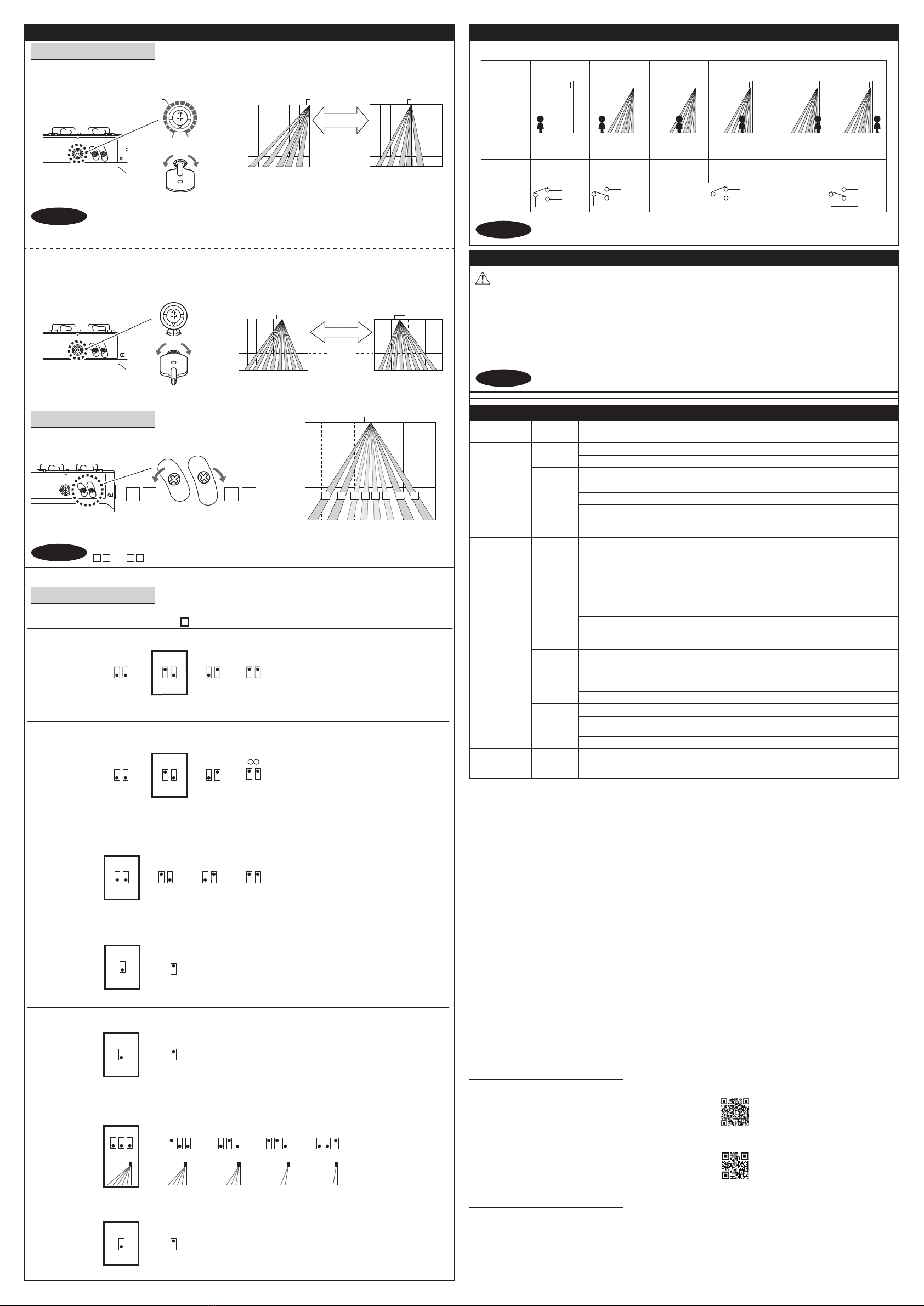
Set the depth rows with
dipswitches 9, 10, 11.
All other possible dipswitch
settings will generate 5 rows
active.
When this switch is set to "ON", presence detection is active in all rows.
When using more than one sensor close
to each other, set the frequency different
for each sensor.
When setting the presence timer follow the
procedure.
1.Select the presence time.
2.Switch the power ON and OFF to prevent the
door remains open for the duration of the
choosen presence detection time.
3.To enable the presence detection, do not enter
the detection area for 10 s.
Set the sensitivity according to the mounting
height and site conditions. The values below are
indicative only.
Row
adjustment
Presence detection
active in all rows
Function Comment
( Factory setting)
Setting
Low or Middle
High
S-High
: 2.0m to 2.5 m
: 2.3 m to 2.7 m
: 2.5 m to 3.0 m
1 2
Left
eliminated
7 8
Right
eliminated
-6° +10°
DeepShallow
3.5°×23.5°×2
LeftRight
Adjustments
1. Area angle adjustment
a. Area depth angle adjustment
The angle of the detection area can be moved 7° left or right in 2 steps.
b. Area width angle adjustment
Adjust the detection area width by the adjustment screws.
2. Area width adjustment
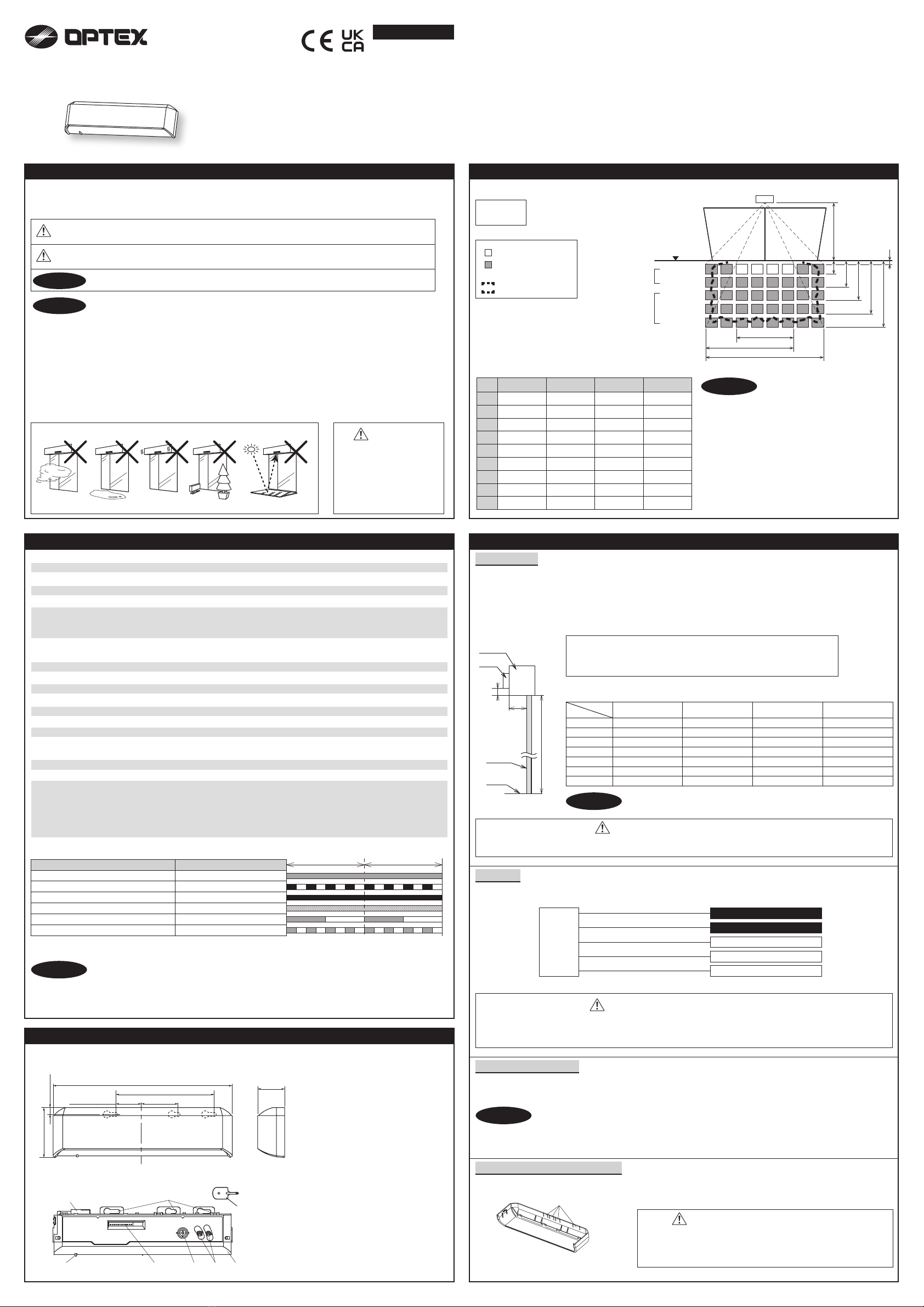
1. Make sure that the detection area does not overlap with the door/header, and there is
no highly reflecting object near the detection area otherwise ghosting/signal saturation may occur.
2. When adjusting the depth angle < 0°, make sure the sensor does not detect the door.
NOTE
When setting the detection area width make sure to turn the adjustment screws until it clicks.
and cannot be eliminated independently.
1 2 7 8
NOTE
1. When turning the power ON, always walk-test the detection area to ensure the proper operation.
2. Do not place any objects that move or emit light in the detection area. (e.g. plant, illumination, etc.)
Inform building owner/operator of the following items
1. Always keep the detection window clean. If dirty, wipe the window with a damp cloth.
Do not use any cleaner/solvent.
2. Do not wash the sensor with water.
3. Do not disassemble, rebuild or repair the sensor yourself, otherwise an electric shock may occur.
4. When the operation indicator blinks Green, contact your installer or service engineer.
5. Always contact your installer or service engineer when changing the settings.
6. Do not paint the detection window.
WARNING
NOTE
Door opens
when no one
is in the
detection area.
(Ghosting)
Unstable Waterdrops on the detection window.
The detection area overlaps with that
of another sensor. Check Adjustments 3 dipswitch 5, 6.
Objects that move or emit light in the
detection area. Remove the objects.
Sensitivity is too high. Set the sensitivity lower.
Adjust the detection area to "Deep"(outside).
Use the rain-cover. (Separately available)
Or wipe the detection window with a damp cloth.
Do not use any cleaner or solvent.
Or install in a place keeping the waterdrops off.
The detection area overlaps with the
door/header.
Door operation Operation
indicator Possible cause Possible countermeasures
None Wrong power supply voltage. Set to the stated voltage.
Wrong wiring or connection failure. Check the wires and connector.
Door does not
open when a
person enters
the detection
area.
Unstable
Wrong detection area positioning. Check Adjustments 1, 2, 3.
Sensitivity is too low. Set the sensitivity higher.
Short presence timer. Set the presence timer longer.
Dirty detection window. Wipe the detection window with a damp cloth.
Do not use any cleaner or solvent.
Wrong wiring or settings. Check the wires and/or dipswitches.Proper
Troubleshooting
Wrong setting of dipswitches. Check Adjustments 3 dipswitch 7, 8, 12.
Proper
Wrong wiring or connection failure. Check the wires and connector.
Fast
Green
blinking
Dirty detection window. Wipe the detection window with a damp cloth.
Do not use any cleaner or solvent.
Sensitivity is too low. Set the sensitivity higher.
Sudden change in the detection area.
Check Adjustments 3 dipswitch 1 to 4. If the
problem still persists, hard-reset the sensor.
(Turn the power OFF and ON again)
Proper
Door remains
open
Contact your installer or service engineer.Sensitivity too low or sensor failure.
Remove highly reflecting objects from the
detection area. Or lower the sensitivity.
Or change the area depth angle.
Proper
operation Signal saturation.
Slow
Green
blinking
3. Dipswitch settings
Front view [m(feet,inch)]
2.0
(6'7")
2.0
(6'7")
1.0
(3'3")
1.0
(3'3")
0
2.0(6'7")
3.0(9'10")
1 2 3 4 5 6 7 8
[m(feet,inch)]
ShallowDeep
2.0(6'7")
3.0(9'10")
Side view
2.0
(6
'
7
"
)
1.0
(3
'
3
"
)
0
3.0
(9
'
10
"
)
2.0
(6
'
7
"
)
1.0
(3
'
3
"
)
1.0
(3
'
3
"
)
0
[m(feet,inch)]
Front view
Left Right
2.0
(6
'
7
"
)
1.0
(3
'
3
"
)
1.0
(3
'
3
"
)
0
2.0(6
'
7
"
)
3.0(9
'
10
"
)
2.0
(6
'
7
"
)
1.0
(3
'
3
"
)
1.0
(3
'
3
"
)
0
Entry
Power OFF Outside of
detection area
Entry into 3rd to
5th row
Status - Stand-by Motion detecion
active
Entry into
2nd row
Entry into
1st row
Outside of
detection area
Motion/presence detection active
Stand-by
Orange Red Redblinking Green
Yellow
Green
White
Output
Operation
indicator GreenNone
Yellow
Green
White
Yellow
Green
White
Yellow
Green
White
Check the operation in the operation mode according to the chart below.
Checking
The door may open once after the power is switched ON.
NOTE
0°
Contact
5-8-12, Ogoto, Otsu, Shiga, 520-0101 Japan
OPTEX CO., LTD.
Manufacturer
OPTEX (EUROPE) LTD.
Unit 13 Cordwallis Park Clivemont Road SL6 7BU Maidenhead, Berkshire United Kingdom
Legal representative (UK only)
Europe, Middle-East and Africa Subsidiary
OPTEX TECHNOLOGIES B.V.
Henricuskade 17, 2497 NB The Hague, The Netherlands
www.optex-europe.com Tel : +31(0)70 419 41 00
North and South America Subsidiary
OPTEX INCORPORATED
10741 Walker Rd. Suite 300 Cypress, CA 90630 U.S.A
www.optexamerica.com Tel : +1(800)877 6656

Other Optex Accessories manuals

Optex AX-250PLUS User manual

Optex

Optex AX-250PLUS User manual

Optex OA-4500S User manual

Optex

Optex OA-4500S User manual

Optex OVS-01CC User manual

Optex

Optex OVS-01CC User manual

Optex Elite OA-603 User manual

Optex

Optex Elite OA-603 User manual

Optex X-ZONE User manual

Optex

Optex X-ZONE User manual

Optex VIBRO User manual

Optex

Optex VIBRO User manual

Optex Prosafe OA-1V User manual

Optex

Optex Prosafe OA-1V User manual

Optex Fiber SenSys Terrain Defender TD 100 User manual

Optex

Optex Fiber SenSys Terrain Defender TD 100 User manual

Optex X-Zone T User manual

Optex

Optex X-Zone T User manual

Optex OAM-DUAL II User manual

Optex

Optex OAM-DUAL II User manual

Optex Accurance-3D A3001CB Manual

Optex

Optex Accurance-3D A3001CB Manual

Optex BGS-V2000 Series User manual

Optex

Optex BGS-V2000 Series User manual

Optex OVS-01GT User manual

Optex

Optex OVS-01GT User manual

Optex V2 Series User manual

Optex

Optex V2 Series User manual

Optex OVS-01GT User manual

Optex

Optex OVS-01GT User manual

Optex i-oneX T User manual

Optex

Optex i-oneX T User manual

Optex Reaction One User manual

Optex

Optex Reaction One User manual

Optex TS-1000-D User manual

Optex

Optex TS-1000-D User manual

Optex ProSafe OA-Presence User manual

Optex

Optex ProSafe OA-Presence User manual

Optex OAM-DUAL TE User manual

Optex

Optex OAM-DUAL TE User manual

Optex i-OneX T User manual

Optex

Optex i-OneX T User manual

Optex HX-80N User manual

Optex

Optex HX-80N User manual

Optex ViiK Exposed Type OVS-02GT Series User manual

Optex

Optex ViiK Exposed Type OVS-02GT Series User manual

Optex OA-AXIS T User manual

Optex

Optex OA-AXIS T User manual

Popular Accessories manuals by other brands

Petzl Astro Bod Fast TECHNICAL NOTICE

Petzl

Petzl Astro Bod Fast TECHNICAL NOTICE

Way Elio Use and maintenance manual

Way

Way Elio Use and maintenance manual

Shel lab SCO6AD Installation & operation manual

Shel lab

Shel lab SCO6AD Installation & operation manual

Sengate PH-15FA Manual instruction

Sengate

Sengate PH-15FA Manual instruction

Aqara FP2 user manual

Aqara

Aqara FP2 user manual

Bimar PISOLO SC120 Instruction book

Bimar

Bimar PISOLO SC120 Instruction book

AHA SIMPO-220 user manual

AHA

AHA SIMPO-220 user manual

Bosch BTOK installation instructions

Bosch

Bosch BTOK installation instructions

Omron F400 - 06-1999 Operation manual

Omron

Omron F400 - 06-1999 Operation manual

Rohde & Schwarz R&S RT-ZC10B user manual

Rohde & Schwarz

Rohde & Schwarz R&S RT-ZC10B user manual

Schmidt SS 20.700 quick guide

Schmidt

Schmidt SS 20.700 quick guide

Eleiko Vmaxpro manual

Eleiko

Eleiko Vmaxpro manual

Wimberley CK-200 instructions

Wimberley

Wimberley CK-200 instructions

MHZ CLASSIC manual

MHZ

MHZ CLASSIC manual

EluneVision Luna user manual

EluneVision

EluneVision Luna user manual

Spacesaver Eclipse Powered System owner's manual

Spacesaver

Spacesaver Eclipse Powered System owner's manual

ZigBoat Schuko ZB207 owner's manual

ZigBoat

ZigBoat Schuko ZB207 owner's manual

Xantech 282M datasheet

Xantech

Xantech 282M datasheet

manuals.online logo
manuals.online logoBrands
  • About & Mission
  • Contact us
  • Privacy Policy
  • Terms and Conditions

Copyright 2025 Manuals.Online. All Rights Reserved.