opticis M1-2Rx-TR User manual

Step 4
Remove the module dust covers and connect each duplex LC fiber cable one
by one to each of 4 LC receptacles of the Transmitter and Receiver boxes, as
shown in Fig. 2. Plug A to A and B to B. Carefully recheck polarities and
ensure the duplex connectors are fully engaged.
Step 5
Connect each RJ-45C plug of the DDC cable to each RJ-45C receptacle of
the Transmitter and Receiver boxes.
Figure 4 – Connection of 2 duplex LC fiber cables
Step 6
Connect an AC/DC power adapter to either of the Transmitter and Receiver
boxes as your availability of AC outlets.
Figure 5 – Connection of AC/DC power adaptor
Step 7
Power on the media receiver or computer and display.
Tip 1: After initial installation as guided in the above, we recommend you to
power On and Off while all connections are set and the Tx/Rx boxes are
powered in.
Tip 2: Avoid “hot plugging” the Tx or Rx boxes as this is not recommended
practice with live digital voltages.
1-4 Installation (continued)
Installation
Important: Please use the installation procedure below. Improper, or no
operation may result if the start-up sequence is not correctly followed.
Step 1
Carefully unpack the contents of the shipping group.
Step 2
With system power turned off, connect the upstream Transmitter box to the
DVI receptacle of a media receiver or a computer by one DVI copper cable in
the shipping group.
Figure 2 – Connection of DVI cable between Transmitter box and media receiver
Step 3
In the same way as above, connect the Receiver box into the DVI receptacle
of the display by the other DVI copper cable.
Figure 3 – Connection of DVI cable between Receiver box and display
Notice: Please DO NOT look directly into the LC receptacles of the
Transmitter box, while it is powered on, although this product is regulated
strictly enough to operate under the Laser Class I, classified by CDRH/FDA
for eye safety.
1-3 Installation

Troubleshooting
The display displays only black screen.
•Check that all AC and DC plugs and jacks used by external power
supplies (both Opticis and others) are firmly connected.
•Ensure that power bars are live.
•Ensure that the Tx and Rx boxes plug correctly to the media receiver
or computer and display, respectively.
•Check if the media receiver or computer and display are powered on
and properly booted.
•Re-boot up the system after reconnecting the optical system cable.
Screen is distorted or displays noises.
•Check if the graphic resolution is properly set. Go to the display
properties and tap the settings. Ensure that the resolution sets less
than SXGA (1,600x1,200) at 60Hz refresh ratio.
•Reset the system.
•Power down, disconnect and reconnect the optical system cable or
DC power adaptors, and power up.
Maintenance
No special maintenance is required for the optical system cables and power
supplies. Ensure that the cables and power modules are stored or used in a
benign environment free from liquid or dirt contamination.
There are no user serviceable parts. Refer all service and repair issues to
Opticis or its authorized distributor.
Technical Support and Service
For commercial or general product support, contact your reseller. For
website at www.opticis.com.
1-5 Troubleshooting, Maintenance, Technical Support
System Requirements for Setup
Hardware requirements
You have a Media Receiver or a graphic controller card with a
DVI (Digital Visual Interface) port in your Windows/Mac (Mac is
option), or SUN system. It should support the maximum graphic
resolution feature of the display to be connected.
In case of using a computer, no special memory size, CPU
speed and chipsets are required.
Proper initial trial of the entire platform with its application using
a short length copper cable is recommended prior to install with
the optical link.
Software requirements
No special needs, if the DVI graphic controller and display
peripheral are operational with the platform’s OS and
application.
AC/DC Power Adapter Technical Advisory
The power of M1-2Rx-TR is designed to supply to both modules of
Tx and Rx over the DDC cable by plugging the power jack to either
of their power plugs.
1-2 System Requirements for Setup

Welcome!
Congratulations on your purchase of the M1-2Rx-TR, Optical DVI Module.
This manual contains information that will assist you in installing and operating
the product.
Product Description
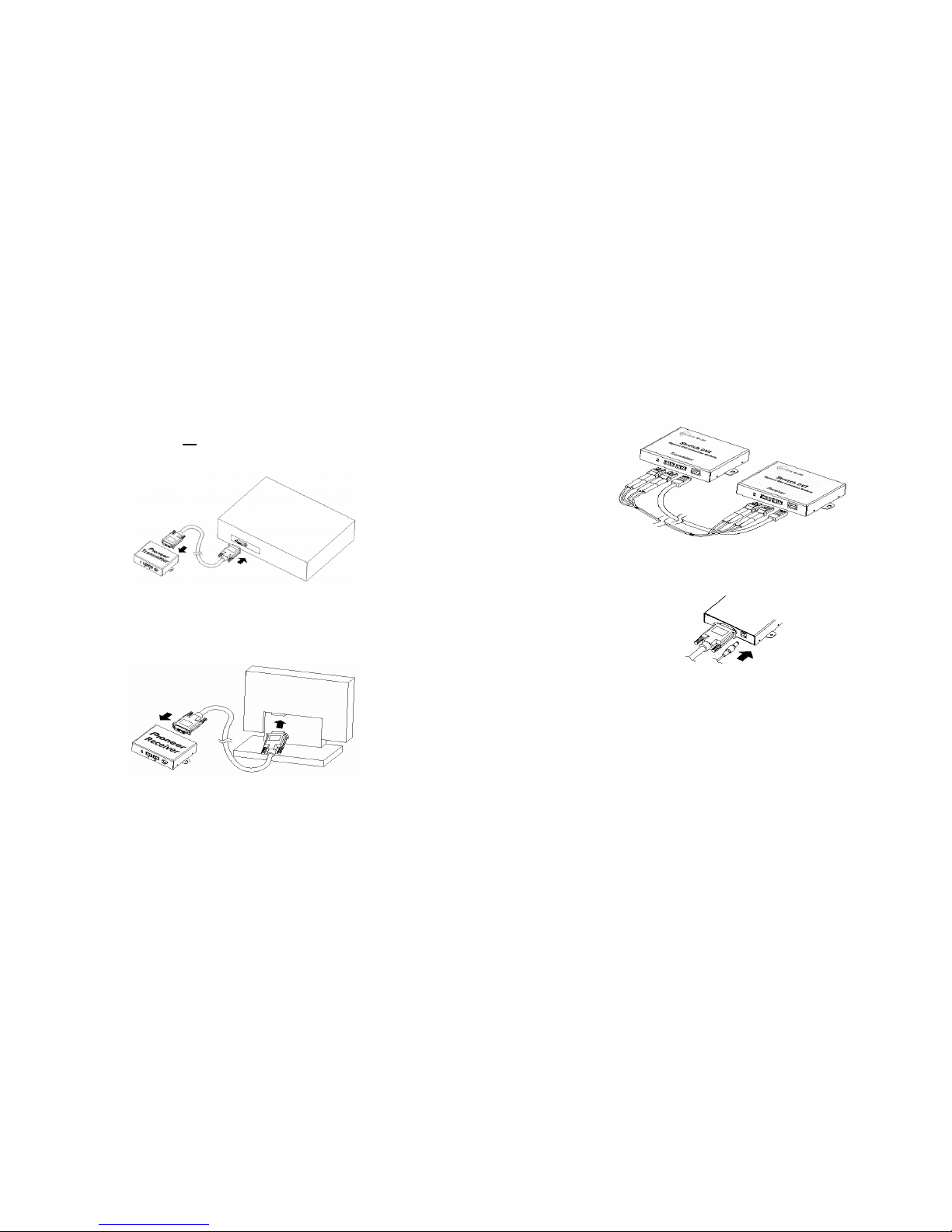
The M1-2Rx-TR module offers 100 meters extension of high-resolution digital
graphic data over fiber, directly connected between computers or media
receivers and displays. Two boxes, located one in the media receiver and the
other in the display are connected to each of them by a 1.0 m DVI copper
cable. Between two boxes, the 4 LC patch cord fiber bundled cable enables to
transmit 4 channels (R,G,B,Clk) of graphic data over it and the DVI Digital
Display Channel (DDC2B) interface is performed over a bundled copper cable,
so called as DDC cable, which optionally has RJ-45C connectors.
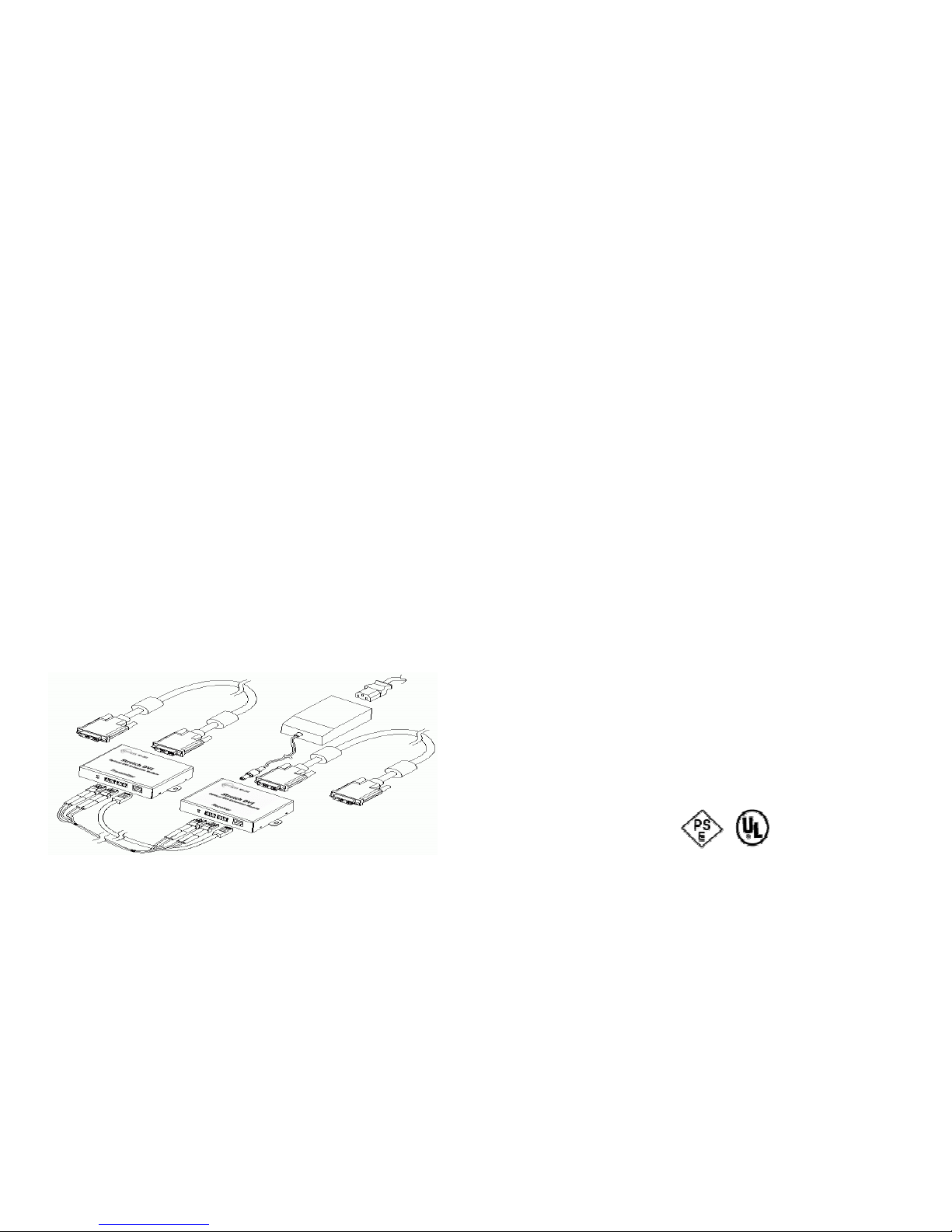
Shipping Group of M1-2Rx-TR Optical DVI Module
Tx and Rx boxes: One (1) Transmitter (Tx) Box and One (1)
Receiver (Rx) Box.
Option: DDC cable with RJ-45C.
Option: 4 LC Patch Cord fiber bundled cable (Multimode glass
fiber).
AC/DC power adapter: One (1) +12V units
User’s Manual
Quick Installation Note
Figure 1 – Overall Optical DVI Module
1-1 Welcome, Product Description
Product Specifications
M1-2Rx-TR Optical DVI Module
Compliance with DVI standard: supports DVI 1.0, using fiber-optic
communication links and DDC2B.
Extension limit: 100m (330feet) for UXGA (1,600x1,200) at 60Hz
refresh rate in ultimate operation.
Graphic Transmission Bandwidth: supports up to 1.65Gbps
bandwidth per graphic channel at UXGA at 60Hz.
Fiber-optic Connection: The transmitter and receiver boxes of M1-
2Rx-TR have 2 duplex LC receptacles connected to four 62.5/125µm
or 50/125µm Multi-Mode glass fibers cables.
Mechanical specifications of Tx and Rx boxes
Dimensions: 38mm / 19mm / 72mm (W/H/D)
Weight: 46.0 ±1.5 gr for each of Tx and Rx.
Environmental Specifications
Operating temperature: -10°C to 50°C
Storage temperature: - 30°C to 60°C
AC/DC Power Adapter
Power Input: Universal AC 85-264V, 50/60Hz, AC power cord with
power jack.
Power Output: +12 V, 3.0 A SMPS DC-power Adapter
Cord DC Jack & length: Core is 12 V and outer cylinder is GND.
Length is 18.5 cm
AC Cord length: 1.8m
Certification: PSE, UL, cUL, FCC, CE, TUV-GS
1-6 Product Specifications

Warranty Information
1 (One) Year Warranty
Opticis warrants this optical DVI module to be free from defects in
workmanship and materials, under normal use and service, for a period of
one (1) year from the date of purchase from Opticis or its authorized resellers.
If a product does not work as warranted during the applicable warranty period,
Opticis shall, at its option and expense, repair the defective product or part,
deliver to customer an equivalent product or part to replace the defective item,
or refund to customer the purchase price paid for the defective product.
All products that are replaced will become the property of Opticis.
Replacement products may be new or reconditioned.
Any replaced or repaired product or part has a ninety (90) day warranty or the
reminder of the initial warranty period, whichever is longer.
Opticis shall not be responsible for any software, firmware, information, or
memory data of customer contained in, stored on, or integrated with any
products returned to Opticis for repair under warranty or not.
Warranty Limitation and Exclusion
Opticis shall have no further obligation under the foregoing limited warranty if
the product has been damaged due to abuse, misuse, neglect, accident,
unusual physical or electrical stress, unauthorized modifications, tampering,
alterations, or service other than by Opticis or its authorized agents, causes
other than from ordinary use or failure to properly use the product in the
application for which said product is intended.
1-7 Warranty Information
Manual Contents
__________________________________________
Manual Contents 1-0
Welcome!, Product Description 1-1
System Requirements for Setup 1-2
Installation 1-3
Troubleshooting, Maintenance, Technical Support 1-5
Product Specifications 1-6
Warranty Information 1-7
Regulatory Statements 1-8
Pictorials
Figure 1 – Overall Optical DVI Module 1-1
Figure 2 – Connection of DVI cable between
Tx box and media receiver 1-3
Figure 3 – Connection of DVI cable between
Rx box and display 1-3
Figure 4 – Connection of 2 duplex LC fiber cables 1-4
Figure 5 – Connection of AC/DC power adaptor 1-4

FCC/CE Statement for regulation of Electro-magnetic
emission
This device complies with part 15 of FCC Rules. Operation is subject to the
following two conditions: (1) this device may not cause harmful interference,
and (2) this device must accept any interference received, including
interference that may cause undesired operation. This equipment has been
tested and found to comply with the limits for a Class B digital device,
pursuant to part 15 and 2 of FCC Rules, EN 55022/55024/61000-3 for CE
certification. These limits are designed to provide reasonable protection
against harmful interference when the equipment is operated in a residential
installation. This equipment generates, uses, and can radiate radio frequency
energy and. if not installed and used in accordance with the instruction guide,
may cause harmful interference to radio communications. However, there is
no guarantee that interference will not occur in a particular installation. If this
equipment does cause harmful interference to radio or television reception,
which can be determined by turning the equipment off and on, the user is
encouraged to try to correct the interference by one or more of the following
measures:
•Re-orient or relocate the receiving antenna.
•Increase the separation between the equipment and the receiver.
•Connect the equipment into an outlet on a circuit different from that to
which the receiver is connected.
•Consult a service representative for help.
Properly shielded and grounded cables and connectors must be used in order
to comply with FCC/CE emission limits. Changes or modifications not
expressly approved by the party responsible for compliance could void the
user s authority to operate the equipment.
Certification for Safety
The extension system is certified pursuant to IEC60065 and its AC/DC power
adapter is certified by UL1310, 1950, 60950 for North America, cUL or CSA
for Canada, TUV-CE & GS for EU and PSE for Japan.
Certification of Eye Safety
This laser product is inside implemented by using 850nm VCSEL (Vertical
Cavity Surface Emitting Laser) Transceivers, manufactured by Opticis Co.,
Ltd., which are all certified by CDRH/FDA referred in Accession Number
0210774 as classified in Laser Class 1.
1-8 Regulatory Statements

User’s Manual
for the M1-2Rx-TR
© 2003 Opticis. All Rights Reserved
Revision 1 1230
Opticis Locations
Opticis Co., Ltd. Opticis North America Ltd.
#501 Byucksan Technopia 70 East Beaver Creek Road
434-6 Sangdaewon-Dong, Chungwon-Ku Unit 30
Sungnam City, Kyungki-Do Richmond Hill, Ontario L4B 3B2
462-120, South Korea Canada
Tel: +82 (31) 737-8033 Tel: (905) 882-7019
Fax: +82 (31) 737-8079 Fax: (905) 882-7025
For order support, please contact your Distributor or Reseller.
For technical support, check with the Opticis web site www.opticis.com or
contact [email protected]
Optical DVI Module
®
Table of contents
Other opticis Control Unit manuals
Popular Control Unit manuals by other brands

CCS
CCS Lighting Solution PD3-5024-4-EI Instruction guide

ZIEHL-ABEGG
ZIEHL-ABEGG UNIcon MODBUS Master operating instructions

Broadcom
Broadcom BCM2046 manual

Federal Signal Corporation
Federal Signal Corporation EM3 Installation and maintenance manual

Parker
Parker EP Series Pro-Bloc Installation and operation manual

Honeywell
Honeywell C7110C1040 Mounting instructions