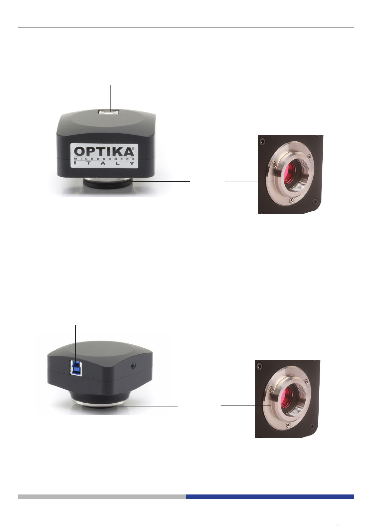
Optika Italy C-B Series User manual

Model
C-B Series
C-B+ Series
C-P Series
C-P(Cooled) Series
C-E2 Series
Camera series C-B / C-B+ / C-P / C-E
INSTRUCTION MANUAL
Ver. 5.2 2022

Page 2
1. Warning 3
2. Safety Information 3
3. Package content 4
3.1 C-B Series 4
3.2 C-B+ Series 4
3.3 C-P Series 5
3.4 C-P (Cooled) 5
3.5 C-E Series 6
4. Unpacking 7
5. Intended use 7
6. Symbols and conventions 7
7. Instrument description 8
7.1 C-B Series 8
7.2 C-B+ / C-P Series 8
7.3 C-P (Cooled) 9
7.4 C-E Series 9
8. Assembling 10
8.1 Assembling on microscope 10
8.1.1 Connection to trinocular port using focusable “C” mount adapter 10
8.1.2 Connection to trinocular port with projection lens 11
8.1.3 Connection to binocular or monocular head 12
8.2 Connecting camera to PC 13
8.2.1 Only for cooled versions 13
8.3 Parfocality adjustment 14
8.3.1 Biological microscope 14
8.3.2 Stereomicroscope with “C” mount adapter 14
8.3.3 Stereomicroscope with projection lens 14
9. Use of camera 15
10. Micrometric Slide M-005 15
Equipment disposal 16
Table of contents

Page 3
1. Warning
This camera is a scientic precision instrument designed to last for many years with a minimum of maintenance. It is built
to high optical and mechanical standards and to withstand daily use. We remind you that this manual contains important
information on safety and maintenance, and that it must therefore be made accessible to the instrument users. We decline
any responsibility deriving from incorrect instrument use uses that does not comply with this manual.
2. Safety Information
Avoiding Electrical Shock
Before plugging in the power supply, make sure that the supplying voltage of your region matches with the operation voltage
of the equipment and that the lamp switch is in o position. Users should observe all safety regulations of the region. The
equipment has acquired the CE safety label. However, users have full responsibility to use this equipment safely. Please
follow the guidelines below, and read this manual in its entirety to ensure safe operation of the unit.

Page 4
① Camera
② Projectionlens
• (C-B10.35x,allothersC-B0.5x)
③ Reductionring30.5mm
④ Reductionring30mm
⑤ Micrometricslide
⑥ USB2.0cable
③ ④ ⑤
①
②
⑥
3.2 C-B+ Series
① Camera
② Projectionlens
③ Reductionring30.5mm
④ Reductionring30mm
⑤ Micrometricslide
⑥ USB3.0cable
③④
⑤
①
②
⑥
3. Package content
3.1 C-B Series

Page 5
3.3 C-P Series
3.4 C-P (Cooled) Series
① Camera
② USB3.0cable
③ Micrometricslide
④ Powersupply+cable
⑤ Transportbox
① ② ③
④
⑤
① Camera
② USB3.0cable
③ Micrometricslide
①
②③

Page 6
3.5 C-E Series
① Camera
② USB2.0cable
③ Reductionring30.5mm
④ Reductionring30mm
①
②③
④

Page 7
4. Unpacking
The device is housed in a moulded Styrofoam container. Remove the tape from the edge of the container and lift the top
half of the container. Take some care to avoid that the optical items fall out and get damaged.
Do not touch with bare hands optical surfaces such as lenses, lters or glasses. Traces of grease or other
residuals may deteriorate the nal image quality and corrode the optics surface in a short time.
5. Intended use
Standard models
For research and teaching use only. Not intended for any animal or human therapeutic or diagnostic use.
IVD Models
Also for diagnostic use, aimed at obtaining information on the physiological or pathological situation of the subject.
6. Symbols and conventions
The following chart is an illustrated glossary of the symbols that are used in this manual.
CAUTION
This symbol indicates a potential risk and alerts you to proceed with caution.
ELECTRICAL SHOCK
This symbol indicates a risk of electrical shock.

Page 8
7. Instrument description
7.1 C-B Series
7.2 C-B+ / C-P Series
USB 2.0
CABLE SOCKET
“C” MOUNT
USB 3.0 CABLE SOCKET
(BACK OF THE CAMERA)
“C” MOUNT

Page 9
USB2.0 CABLE SOCKET
MICROSCOPE
CONNECTION
EXTERNAL POWER
SUPPLY SOCKET
USB2.0
CABLE SOCKET
USB3.0
CABLE SOCKET
OPERATION LED
7.4 C-E Series
7.3 C-P (Cooled)

Page 10
8. Assembling
8.1 Assembling on microscope
8.1.1 Trinocular port with focusable “C” mount adapter
1. Remove the dust cover from camera and from “C” mount
adapter.
2. Screw the “C” mount adapter to the camera’s thread. (Fig. 1)
FFig. 1ig. 1
FFig. 2ig. 2
FFig. 3ig. 3
3. Loosen the clamping screw on the trinocular port of the mi-
croscope, remove the dust cover and install the camera ”C”
mount unit previously assembled. (Fig. 2)
4. Tighten the clamping screw rmly. (Fig. 3)

Page 11
8.1.2 Trinocular port with projection lens
1. Remove the dust cover from camera and from projection
lens.
2. Screw the projection lens to the camera’s thread. (Fig. 4)
FFig. 4ig. 4
FFig. 5ig. 5
FFig. 6ig. 6
FFig. 7ig. 7
• Installing on stereomicroscopes
4. Insert the nal part of the projection lens into the empty hole
of the photo tube. (Fig. 6)
• Installing C-E2 camera
5. Insert the microscope connector in the empty hole of the pho-
to tube. (Fig. 7)
• Installing on biological microscopes
3. Insert the nal part of the projection lens into the empty hole
of the photo tube. (Fig. 5)

Page 12
8.1.3 Binocular or monocular head
• Any OPTIKA monocular or binocular microscope/stereomi-
croscope.
• Any non-OPTIKA monocular or binocular microscope/stereo-
microscope.
1. Remove the dust cover from camera and from projection
lens.
2. Screw the projection lens to the camera’s thread. (Fig. 8)
FFig. 9ig. 9
FFig. 8ig. 8
FFig. 10ig. 10
FFig. 11ig. 11
3. Remove one eyepiece from the observation head. (Fig. 9)
4. Insert the nal part of the projection lens into the empty eye-
piece sleeve. (Fig. 10)
5. In case of eyepiece sleeve with diameter 30 or 30.5 mm use
the adapter rings. (Fig. 11)

Page 13
8.2 Connecting camera to PC
1. Connect one terminal of the USB cable to the camera con-
nector and the other terminal to a USB port on the computer.
(Fig. 12)
• NOTE: USB3.0 cameras can be connected to a USB2.0 port.
The camera will operate normally, with some limitations due
to improper power supply to the camera.
• The SW in any case will warn that the USB3.0 camera works
in 2.0 mode indicating next to the camera name “(USB2.0)”
FFig. 12ig. 12
FFig. 13ig. 13
①
USB2.0 USB3.0
8.2.1 Only for cooled versions
Connect the supplied power adapter to the connector ①to pow-
er the camera cooling system. (Fig. 13)

Page 14
8.3 Parfocality adjustment
In order to have the same focus when observing the specimen
through the eyepieces and on the screen/monitor, please check
that the microscope is properly installed and follow the instruc-
tions below.
8.3.1 Biological microscope
1. Use a low power objective and focus the specimen.
2. Switch to the highest dry objective available on the micro-
scope (40x or 60x) and focus the specimen again.
3. Turn on the live-view on the camera, without changing the
focus on the microscope.
4. While observing the image on the screen/monitor, adjust the
focus by turning the knurled knob on the C-mount adapter.
(Fig. 14)
8.3.2 Stereomicroscope with “C” mount adapter
1. Use a low power magnication and focus the specimen.
2. Reach the highest magnication available using the zoom
knob and then focus the specimen again.
3. Turn on the live-view on the camera, without changing the
focus on the microscope.
4. While observing the image on the screen/monitor, adjust the
focus by turning the knurled knob on the C-mount adapter.
(Fig. 14)
FFig. 14ig. 14
FFig. 15ig. 15
①
②
FFig. 16ig. 16
8.3.3 Stereomicroscope with projection lens
1. Use a low power magnication and focus the specimen.
2. Reach the highest magnication available using the zoom
knob and then focus the specimen again.
3. Turn on the live-view on the camera, without changing the
focus on the microscope.
4. While observing the image on the screen/monitor, unscrew
the xing knob ① of the trinocular port (Fig. 15) and move
up or down the movable part of the adapter ② until the focus
is achieved on the camera. (Fig. 16)
5. Lock the xing knob ①. (Fig. 15)
The proper parfocality adjustment is obtained when the same
focus is reached when looking into the eyepieces and on the
screen/monitor.

Page 15
9. Use of camera
For biological microscopes calibration
1 DIV=0.01mm
The camera is driven by a software.
Two levels of software are available: PROVIEW and LITEVIEW.
Inside the package is enclosed a Function Table showing the several software functions.
It will be the user’s responsibility to decide which level of software best meets his needs.
The software can be downloaded from the site:
http://www.optikamicroscopes.com/optikamicroscopes/optika-support/download-drivers-softwares/
You will have to register to download the .zip le.
Once the le has been downloaded, you will have to run the setup.exe le.
At the end of the installation it is possible to start the software.
• NOTE: no driver installation is required for the cameras. The software setup procedure automatically installs
all the needed drivers for the correct operation of the camera.
The software’s User Manual is available in PDF format within the application itself and can be opened using the “F1” func-
tion key.
You must have Acrobat Reader installed to view the manual.
The manual contains all the operating instructions for using the camera and for the various functions of the software.
For stereo microscopes calibration
1 DIV=0.1mm
0 1 2 3 4 5 6 7 8 9 10
10. Micrometric Slide M-005
Micrometric slide, 26x76mm, with 2 scales
(1mm/100div. for biological microscopes / 10mm/100div. for stereomicroscopes)

Page 16
Equipment disposal
Art.13 Dlsg 25 July 2005 N°151. “According to directives 2002/95/EC, 2002/96/EC and 2003/108/EC relating to the reduc-
tion in the use of hazardous substances in electrical and electronic equipment and waste disposal.”
The basket symbol on equipment or on its box indicates that the product at the end of its useful life should be collected sep-
arately from other waste. The separate collection of this equipment at the end of its lifetime is organized and managed by
the producer. The user will have to contact the manufacturer and follow the rules that he adopted for end-of-life equipment
collection. The collection of the equipment for recycling, treatment and environmentally compatible disposal, helps to pre-
vent possible adverse eects on the environment and health and promotes reuse and/or recycling of materials of the equip-
ment. Improper disposal of the product involves the application of administrative penalties as provided by the laws in force.

OPTIKA S.r.l.
Via Rigla, 30 - 24010 Ponteranica (BG) - ITALY Tel.: +39 035.571.392
OPTIKA
Spain
OPTIKA
USA
OPTIKA
China
OPTIKA
India
OPTIKA
Central America
®
®
®
®
®
®

Modello
Serie C-B
Serie C-B+
Serie C-P
Serie C-P(Cooled)
Serie C-E2
Serie telecamere C-B / C-B+ / C-P / C-E
MANUALE DI ISTRUZIONI
Ver. 5.2 2022

Pagina 19
1. Avvertenza 20
2. Informazioni sulla sicurezza 20
3. Contenuto della confezione 21
3.1 Serie C-B 21
3.2 Serie C-B+ 21
3.3 Serie C-P 22
3.4 C-P (Cooled) 22
3.5 Serie C-E 23
4. Disimballaggio 24
5. Uso previsto 24
6. Simboli 24
7. Descrizione dello strumento 25
7.1 Serie C-B 25
7.2 Serie C-B+ / C-P 25
7.3 Serie C-P (Cooled) 26
7.4 Serie C-E 26
8. Assemblaggio 27
8.1 Montaggio a microscopio 27
8.1.1 Testa trinoculare con passo “C” fochettabile 27
8.1.2 Testa trinoculare con lente di proiezione 28
8.1.3 Testa binoculare o monoculare 29
8.2 Connessione a PC della telecamera 30
8.2.1 Soloperversionirareddate 30
8.3 Regolazione della parafocalità 31
8.3.1 Microscopio biologico 31
8.3.2 Stereomicroscopio con passo “C” 31
8.3.3 Stereomicroscopio con lente di proiezione 31
9. Uso della telecamera 32
10. Vetrino Micrometrico M-005 32
Smaltimento 33
Sommario

Pagina 20
1. Avvertenza
Questo apparecchio è uno strumento scientico di alta precisione, progettato per durare a lungo con una minima
manutenzione; la realizzazione è secondo i migliori standard ottici e meccanici, per poter essere utilizzato quotidianamente.
Vi ricordiamo che questo manuale contiene informazioni importanti per la sicurezza e per la manutenzione dello strumento,
e deve quindi essere messo a disposizione di coloro che lo utilizzeranno.
Decliniamo ogni responsabilità derivante da un utilizzo dello strumento non indicato nel presente manuale.
2. Informazioni sulla sicurezza
Per evitare shock elettrici
Prima di collegare il cavo di alimentazione alla presa elettrica, assicurarsi che il voltaggio della rete locale coincida con il
voltaggio dello strumento e che l’interruttore dell’illuminazione sia nella posizione “OFF”.
Gli utenti dovranno seguire tutte le norme di sicurezza locali. Lo strumento è certicato CE. In ogni caso, gli utilizzatori sono
gli unici responsabili per un utilizzo sicuro dello strumento. Per l’utilizzo in sicurezza dello strumento è importante attenersi
alle seguenti istruzioni e leggere il manuale in tutte le sue parti.
Other manuals for C-B Series
1
This manual suits for next models
13
Table of contents
Languages:
Other Optika Italy Digital Camera manuals

Optika Italy
Optika Italy OPTIKAM B1 User manual

Optika Italy
Optika Italy C-HP4SC User manual

Optika Italy
Optika Italy H Series User manual

Optika Italy
Optika Italy H Series User manual

Optika Italy
Optika Italy H Series User manual

Optika Italy
Optika Italy H Series User manual

Optika Italy
Optika Italy SZP Series User manual

Optika Italy
Optika Italy H Series User manual

Optika Italy
Optika Italy C-HA User manual

Optika Italy
Optika Italy C-D Series User manual