Optika Italy C-HA User manual

Ver. 1.0 2019
Model
C-HA
HDMI Autofocus camera, 2 MP CMOS
INSTRUCTION MANUAL

Page 2
Summary
1. Warning 3
2. Symbols and conventions 3
3. Safety Information 3
4. Intended use 3
6. Unpacking 5
7. Assembling 5
7.1 Camera installation 6
7.1.1 Use of “C” mount adapters 6
7.1.2 Use of projection lens 7
7.2 Camera connection 7
7.3 Parfocality adjustment 8
8. Use of the camera 9
8.1 “Control” Menu 9
8.1.1 “Focus” Section 10
8.1.2 “AF ROI” Section 10
8.1.3 “Exposure” Section 12
8.1.4 “Color” Section 13
8.1.5 “Function” Section 13
8.2 “Crosshair” Menu 16
8.3 “System” Menu 17
9. Maintenance 18
Equipment disposal 19

Page 3
1. Warning
This camera is a scientic precision instrument designed to last for many years with a minimum of maintenance.
It is built to high optical and mechanical standards and to withstand daily use. We remind you that this manual
contains important information on safety and maintenance, and that it must therefore be made accessible to the
instrument users. We decline any responsibility deriving from incorrect instrument use uses that does not comply
with this manual.
2. Symbols and conventions
The following chart is an illustrated glossary of the symbols that are used in this manual.
CAUTION
This symbol indicates a potential risk and alerts you to proceed with caution.
ELECTRICAL SHOCK
This symbol indicates a risk of electrical shock.
3. Safety Information
Avoiding Electrical Shock
Before plugging in the power supply, make sure that the supplying voltage of your region matches with the
operation voltage of the equipment and that the lamp switch is in o position. Users should observe all safety
regulations of the region. The equipment has acquired the CE safety label. However, users have full responsibility
to use this equipment safely. Please follow the guidelines below, and read this manual in its entirety to ensure
safe operation of the unit.
4. Intended use
For research and teaching use only. Not intended for any animal or human therapeutic or diagnostic use.

Page 4
5. Overview
HDMI CABLE
SOCKET
POWER
SUPPLY
SOCKET
OPERATING
LED
SD CARD
SLOT
USB MOUSE
PORT

Page 5
6. Unpacking
The device is housed in a moulded Styrofoam container. Take some care to avoid that the optical items
fall out and get damaged. Carefully remove the camera from the container and put it on a stable desk.
Do not touch with bare hands optical surfaces such as lenses, lters or glasses. Traces of grease or other
residuals may deteriorate the nal image quality and corrode the optics surface in a short time.
7. Assembling
Once opened the box, the camera parts are the following:
① Camera
② 16GB micro SD card
③ HDMI cable
④ Wireless mouse + battery
⑤ Power supply
③
④
⑤
①
②

Page 6
7.1 Camera installation
7.1.1 Use of “C” mount adapters
1. Remove dust caps from camera and “C” mount.
2. Screw the “C” mount to camera thread. (Fig. 1)
3. Loose the clamping screw from the trinocular
head. (Fig. 2)
4. Install the previously assembled C-mount +
camera on the trinocular head. (Fig. 3)
5. Tighten the clamping screw rmly. (Fig. 4)
Fig. 1
Fig. 2
Fig. 3
Fig. 4

Page 7
7.1.2 Use of projection lens
1. Remove dust caps from camera and projection
lens.
2. Screw the projection lens to camera thread. (Fig. 1)
3. Insert the projection lens on the trinocular port.
(Fig. 2)
7.2 Camera connection
1. Connect one side of the HDMI cable to the HDMI
socket ①. (Fig. 7)
2. Open the mouse battery cover ②. (Fig. 8)
Fig. 5
Fig. 6
Fig. 8
②
Fig. 7
①

Page 8
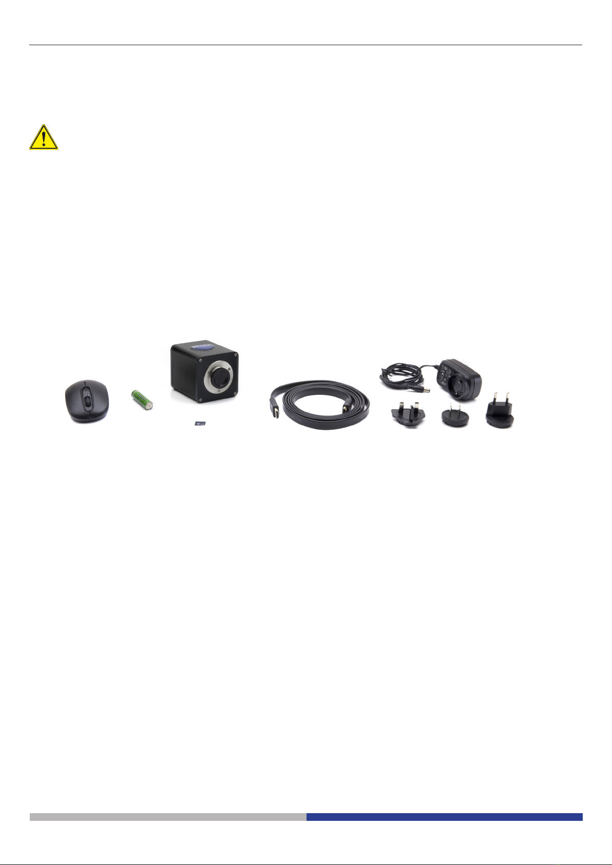
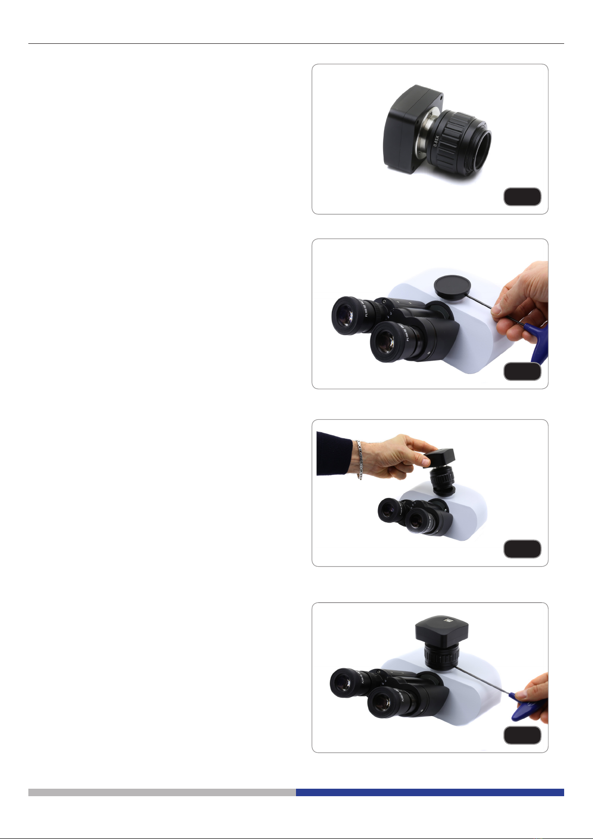
3. Remove the wireless mouse receiver ③. (Fig. 9)
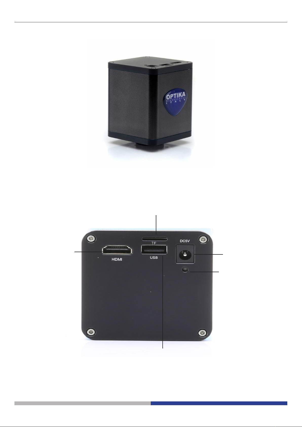
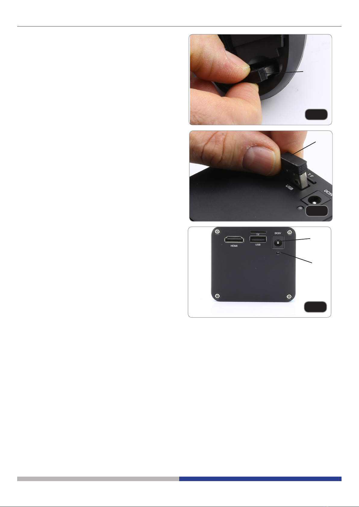
4. Plug the mouse receiver into the USB port ④of
the camera. (Fig. 10)
5. Insert the battery (respect polarity) and put back
the battery cover.
6. Plug the power supply into the DC5V socket ⑤ to
power the camera. (Fig. 11)
• Once the power supply is connected, the ca-
mera takes about 10 seconds to switch on
and the LED ⑥lights up blue. This is not a
defect.
Fig. 9
③
7.3 Parfocality adjustment
In order to have the same focus when observing the specimen through the eyepieces and on the screen/moni-
tor, please verify the microscope is properly installed and set and follow the instructions below.
In case of a biological microscope:
1. Use a low power objective and focus the specimen
2. Switch to the highest dry objective available on the microscope (40x or 60x) and focus the specimen again
3. Turn on the live-view on the camera, without changing the focus on the microscope
4. While observing the image on the screen/monitor, adjust the focus by turning the knurled knob on the C-
mount adapter
In case of a stereomicroscope:
5. Using a low power magnication and focus the specimen
6. Reach the highest magnication available using the zoom knob and then focus the specimen again
7. Turn on the live-view on the camera, without changing the focus on the microscope
8. While observing the image on the screen/monitor, adjust the focus by turning the knurled knob on the C-
mount adapter
The proper parfocality adjustment is obtained when the same focus is reached when looking into the eyepieces
and on the screen/monitor.
Fig. 10
④
Fig. 11
⑤
⑥

Page 9
8. Use of the camera
Camera is supplied with an “on screen” menù, which is activated when the mouse cursor is positioned in the
upper left corner of the monitor.
Moving the cursor to a different area causes the menu to disappear.
8.1 “Control” Menu
“FOCUS”
SECTION
“AF ROI”
SECTION
“EXPOSURE”
SECTION
“COLOR”
SECTION
“FUNCTION”
SECTION

Page 10
8.1.1 “Focus” Section
It is possible to work either in autofocus (AF) or manual focus (MF).
Clicking on “AF” button will allow the camera to work in autofocus mode.
It will be sucient to position the target to be observed in front of the camera lens and the focus will be obtained.
The autofocus will be independent of the optical or digital zoom value of the camera: the camera must have
enough contrast in the sample to be observed.
In the case of objects with low contrast, it is possible that the camera can not get the focus. In this case we re-
commend using manual focus.
• Itisimportanttoremindthatthecameradoesn’thaveaninnityautofocuscapability.Theusermust
approximately focus the specimen with the microscope focusing knobs. From this moment the cam-
era will be able to automatically focus the specimen when the stage is moved to another position or
the slide is changed on the stage.
Clicking on “MF” button, the camera will work in manual focus mode. Activation of the MF button automatically
activate the “MF” slider ①, with which you can operate to focus the camera without having to act on the
microscope focusing knobs.
Clicking on “Click F” the camera is taught which is the optimal focus for the sample that is being observed. From
now on, any movement that will be made on the sample or any change in zoom will have to be compensated
again with a new focus.
If you work in “AF” mode, this operation will not be necessary.
8.1.2 “AF ROI” Section
In the “AF ROI” section it is possible to set the size and the position of the ROI (Region Of Interest) where the
autofocus will be detected.
①

Page 11
ROI size can be either “Large” or Small”. This can be selected by clicking on the arrow ②.
A drop down list will appear. Here it is possible to select te size of the ROI area.
Clicking on the radio button “ROI” ③ will activate or deactivate the ROI.
②
LARGE
SMALL
③

Page 12
ROI can also be moved horizontally or vertically by using the two sliders “Hor” and “Ver” ④, in order to move
the ROI in the position where the user wants the autofocus will be detected.
Horizontal movement ranges from 0 to 16, while vertical movement ranges from 0 to 14.
Clicking on “Set” ⑤ will apply all the settings.
8.1.3 “Exposure” Section
“Exposure” section controls the exposure time and the brightness of the camera.
The camera can work in automatic exposure.
By activating the “AE” function, the camera works completely automatically. In this case it is not possible to act
on the parameters of the camera, therefore in situations of insufficient lighting it is possible that the camera can
not provide optimal image quality.
By activating the “ME” the camera works manually. It is therefore necessary to act on the camera parameters to
adapt the exposure time to the lighting condition of the sample.
Moving the slider relative to “Bright” increases or decreases the exposure time of the camera. Depending on
the amount of light that is used to illuminate the sample under examination, you will have to move to the right
(increase) or to the left (decrease) the cursor to get a perfectly lit image avoiding under or overexposure.
The cursor relative to the “Gain” commands the so-called “gain” of the camera. The gain is a function that allows
you to increase the sensitivity of the camera for shooting in low light. This obviously increases the background
noise.
④⑤

Page 13
8.1.4 “Color” Section
The “Color”section controls the color rendering of the camera.
Activating the “AWB” function, the camera uses automatic white balance. Place an empty slide on the micro-
scope front of the camera sensor and click “AWB”. The camera adjusts the colors output from the camera to the
color temperature of the scene being shot.
Activating the “MWB” function, the camera uses manual white balance. In this case it is necessary to move the
sliders related to Red, Green and Blue to obtain a faithful reproduction of what is being observed.
8.1.5 “Function” Section
“Function” section controls the image display on the monitor.
The “Ezoom” cursor ① allows to vary the magnification of the projection to the monitor of the framed object.
It is possible to change the zoom factor (optical zoom) from 0 to 50 operating on the on the cursor in the on-
screen panel.
①

Page 14
Camera allows to capture single images or videos simply by clicking on the “Capture” ② button for single im-
ages or on “Video” ③ for film sequences of desired length.
Still images or video will be stored on the SD card.
To view images or video the user must remove the SD card , simply pushing down the card. The internal locking
mechanism will release the SD card that can be freely removed from its slot.
To re-insert the SD card: fully insert the card and push it downward until the locking mechanism is engaged.
“FBL” button ④ fully disable the autofocus function of the camera, putting back the sensor motor to the so-called
“zero position”.
By clicking “AF” button or “MF” button again, the camera will allow to obtain an automatic or manual focus.
The “Flip” ⑤ function flips the framed image vertically, while the “Mirror” ⑥ function horizontally flips it. This is
useful for making what is observed in the camera consistent with the real object.
②
③
④
⑥
⑤

Page 15
The “HDR” function ⑦ (High Dynamic Range) optimizes the image quality in the case of subjects with very clear
framed areas together with very dark areas. Often in these conditions the camera favors or clear areas (omitting
the dark areas making them black) or dark areas (with a consequent overexposure of the light areas, making
them almost white).
An “HDR” setting of 0 indicates that the camera will acquire a single image and store it. Increasing the number
(max 3) the camera acquires 3 images at different exposures (usually an underexposure, one with optimal
exposure and one overexposed), combines them to optimize the different zones with different lighting and
creates a single image at exposure “virtually correct”.
The “50 / 60Hz” function ⑧ is used to eliminate flickering of the image due to the power supply frequency.
⑦
⑧

Page 16
The “Default” key ⑨ resets all the settings made and restores the factory settings.
⑨

Page 17
8.2 “Crosshair” Menu
Up to 4 sets of horizontal or vertical rows can be superimposed on the monitor.
These lines can be placed anywhere on the monitor by simply dragging the cursor relative to the desired line.
The lines can be projected with different colors in order to be easily visible on the monitor, depending on the
color of the sample in question.
Clicking with the mouse on the color palette of the desired row opens the context menu, with which you select
the color of choice.

Page 18
The lines, once traced, can be visible or hidden. Clicking on the “Show / Hide” button opens the context menu
with which you can view a “Show” row or hide it “Hide”. The lines, if hidden, will not be deleted from memory but
simply will not be visible.
The “Default” key resets all the settings made and restores the factory settings.
The “Center” button places the lines exactly in the center of the monitor (possibly overlapping the different lines
drawn).
The “Save” button saves the settings of the placed rows.
8.3 “System” Menu
With this menu, the system information of the camera is changed.
The “Edit Time” button changes the current date and time, while the “Save Time” button saves the settings made
just recently.
It is possible to change the menu language from English to Chinese.
The “Information” field displays the current version of the software.

Page 19
9. Maintenance
To think about when and after using the system
• The system should always be kept vertically when moving it and be careful so that no moving parts,
such as the eyepieces, fall out.
• Never mishandle or impose unnecessary force on the device.
• Never attempt to service the device yourself.
• After use, cover the microscope with the provided dust-cover, and keep it in a dry and clean place.
Electrical safety precautions
• Before plugging in the power supply, make sure that the supplying voltage of your region matches
with the operation voltage of the equipment and that the lamp switch is in o-position.
• Users should observe all safety regulations of the region. The equipment has acquired the CE safety
label. However, users do have full responsibility to use this equipment safely.
Cleaning the optics
• If the optical parts need to be cleaned try rst to: use compressed air.
• If that is not sucient: use a soft lint-free piece of cloth with water and a mild detergent.
• And as a nal option: use the piece of cloth moistened with a 3:7 mixture of ethanol and ether.
• Note: ethanol and ether are highly ammable liquids. Do not use them near a heat source, near sparks or
near electric equipment. Use these chemicals in a well ventilated room.
• Remember to never wipe the surface of any optical items with your hands. Fingerprints can damage the
optics.
• Do not disassemble objectives or eyepieces in attempt to clean them.
For the best results, use the OPTIKA cleaning kit (see catalogue).
If you need to send the microscope to Optika for maintenance, please use the original packaging.

OPTIKA S.r.l.
Via Rigla, 30 - 24010 Ponteranica (BG) - ITALY Tel.: +39 035.571.392
info@optikamicroscopes.com - www.optikamicroscopes.com
OPTIKA
Spain
spain@optikamicroscopes.com
OPTIKA
USA
usa@optikamicroscopes.com
OPTIKA
China
china@optikamicroscopes.com
OPTIKA
India
india@optikamicroscopes.com
OPTIKA
Central America
camerica@optikamicroscopes.com
®
®
®
®
®
®
Page 20
Equipment disposal
Art.13 Dlsg 25 July 2005 N°151. “According to directives 2002/95/EC, 2002/96/EC and 2003/108/EC relating
to the reduction in the use of hazardous substances in electrical and electronic equipment and waste disposal.”
The basket symbol on equipment or on its box indicates that the product at the end of its useful life should be
collected separately from other waste. The separate collection of this equipment at the end of its lifetime is or-
ganized and managed by the producer. The user will have to contact the manufacturer and follow the rules that
he adopted for end-of-life equipment collection. The collection of the equipment for recycling, treatment and
environmentally compatible disposal, helps to prevent possible adverse eects on the environment and health
and promotes reuse and/or recycling of materials of the equipment. Improper disposal of the product involves
the application of administrative penalties as provided by the laws in force.
Table of contents
Languages:
Other Optika Italy Digital Camera manuals

Optika Italy
Optika Italy SZP Series User manual

Optika Italy
Optika Italy C-B Series User manual

Optika Italy
Optika Italy C-D Series User manual

Optika Italy
Optika Italy OPTIKAM B1 User manual

Optika Italy
Optika Italy H Series User manual

Optika Italy
Optika Italy H Series User manual

Optika Italy
Optika Italy H Series User manual

Optika Italy
Optika Italy C-HP4SC User manual

Optika Italy
Optika Italy H Series User manual

Optika Italy
Optika Italy H Series User manual