Optika Italy C-HP4SC User manual

Model
C-HP4
C-HP4SC
HDMI Cameras – H Series
INSTRUCTION MANUAL
Ver. 1.0 2023

Page 2
1. Warning 3
2. Safety Information 3
3. Package content 4
3.1 C-HP4 4
3.2 C-HP4SC 4
4. Unpacking 5
5. Intended use 5
6. Symbols and conventions 5
7. Instrument description 6
7.1 Camera control panel 6
7.2 HDMI monitor 6
8. Assembling 7
8.1 C-HP4SC 7
8.2 Parfocality adjustment 9
9. C-HP4 Basic features 10
9.1 Quick Instructions for C-HP4 camera 10
9.1.1 HDMI Mode 10
9.1.2 USB Mode 10
10. C-HP4 User Interface (UI) and its Functions 11
10.1 The Camera Control Panel 12
10.2 The Measurement Toolbar 13
10.3 Camera calibration 15
10.4 Icons and Functions of the Camera Control Toolbar 17
10.4.1 Setting > Measurement 17
10.4.2 Setting>Magnication 18
10.4.3 Setting > Image Format 18
10.4.4 Setting > Video 19
10.4.5 Setting > Storage 20
10.4.6 Setting > Files 20
10.4.7 Setting > Language 21
10.4.8 Setting > Miscellaneous 22
11. Micrometric Slide M-005 23
Equipment disposal 24
Table of Contents

Page 3
1. Warning
This device is a scientic precision instrument designed to last for many years with a minimum of maintenance. It is built
to high optical and mechanical standards and to withstand daily use. We remind you that this manual contains important
information on safety and maintenance, and that it must therefore be made accessible to the instrument users. We decline
any responsibility deriving from incorrect instrument use uses that does not comply with this manual.
2. Safety Information
Avoiding Electrical Shock
Before plugging in the power supply, make sure that the supplying voltage of your region matches with the operation voltage
of the equipment and that the lamp switch is in o position. Users should observe all safety regulations of the region. The
equipment has acquired the CE safety label. However, users have full responsibility to use this equipment safely. Please
follow the guidelines below, and read this manual in its entirety to ensure safe operation of the unit.

Page 4
3. Package content
① Camera
② HDMIcable
③ USB2.0cable
④ Wirelessmouse
⑤ Micrometricslide
⑥ SDcard16GB
⑦ Powersupply
①
②
③
④
⑤
⑥
⑦
3.1 C-HP4
3.2 C-HP4SC
① Camerawithxingplate
② Camerapowersupply
③ Wirelessmouse
④ HDMImonitorwithxingplate
⑤ Monitorpowersupply
⑥ Type“C”L-adapter
⑦ HDMI-to-miniHDMIL-adapter
⑧ HDMIcable
⑨ USB2.0cable
➉ SDcard16GB
⑪ Micrometricslide
③
⑥⑦
⑧
⑪
①
②
④
⑨➉
⑤

Page 5
4. Unpacking
The device is housed in a moulded Styrofoam container. Remove the tape from the edge of the container and lift the top half
of the container. Take some care to avoid that the optical items (objectives and eyepieces) fall out and get damaged. Using
both hands (one around the arm and one around the base), lift the device from the container and put it on a stable desk.
Do not touch with bare hands optical surfaces such as lenses, lters or glasses. Traces of grease or other
residuals may deteriorate the nal image quality and corrode the optics surface in a short time.
5. Intended use
Standard models
For research and teaching use only. Not intended for any animal or human therapeutic or diagnostic use.
IVD Models
Also for diagnostic use, aimed at obtaining information on the physiological or pathological situation of the subject.
6. Symbols and conventions
The following chart is an illustrated glossary of the symbols that are used in this manual.
CAUTION
This symbol indicates a potential risk and alerts you to proceed with caution.
ELECTRICAL SHOCK
This symbol indicates a risk of electrical shock.

Page 6
7. Instrument description
① USBmouseconnector
② USB2.0connector
③ HDMIconnector
④ ON-OFFbutton
⑤ SDcardslot
⑥ Powersupplyplug
⑦ LEDindicator
①②③
④
⑤
⑥
⑦
7.1 Camera control panel
7.2 HDMI monitor
HEADPHONE
MENU DIAL
ON/OFF BUTTON HDMI PORT ①
TYPE C PORT ②
TYPE C PORT ③
MICRO USB PORT ④
① HDMIcameraconnection
② VideoDisplay/Audio/TouchControl
③ PowerSupply/USB3.0port
④ Keyboard/Mouseconnection
NOTE:Whenusingthemonitorinthisconguration,theHeadphone,TypeC②and Micro USB ④ports are not
used.

Page 7
8. Assembling
8.1 C-HP4SC
1. Using the supplied screws, join the xing plate mounted on
the camera ① and the xing plate mounted on the monitor
②. (Fig. 1)
FFig. 2ig. 2
FFig. 1ig. 1
①
③
②
FFig. 3ig. 3
④
⑤
FFig. 4ig. 4
2. Screw the “C” mount adapter ③ to the camera ④. (Fig. 2)
3. Loosen the clamping screw ⑤ on the trinocular port and
remove the dust cap ⑥. (Fig. 3)
⑥
4. Insert the round dovetail of the “C” mount into the empty hole
of the trinocular port, then tighten the clamping screw ⑤.
(Fig. 4)
⑤

Page 8
5. Plug the USB mouse receiver in the “USB MOUSE” port Ⓐ
on the camera. (Fig. 5)
FFig. 5ig. 5
FFig. 6ig. 6
Ⓐ
Ⓑ①
②
6. Connect the cable with the HDMI side ① to the provided HD-
MI-HDMI L-adapter ②. (Fig. 6)
7. Connect the HDMI L-adapter to the “HDMI” port Ⓑ on the
camera.
FFig. 7ig. 7
FFig. 8ig. 8
Ⓒ
Ⓓ
8. Plug mini HDMI cable to the mini HDMI port Ⓒplaced on the
right side of the monitor. (Fig. 7)
9. Insert the SD card into “SD” slot Ⓓ for saving captured imag-
es and recorded videos. (Fig. 8)

Page 9
FFig. 9ig. 9
FFig. 10ig. 10
Ⓕ
Ⓔ
③④
10. Plug the monitor power supply connector ③in the provided
“L” adapter ④. (Fig. 9)
11. Plug the “L” adapter in the “Type C” port Ⓔ placed on the
right side of the monitor.
12. Plug the power supply to the wall outlet.
13. Insert the camera power supply jack in the “DC12V” socket
Ⓕ. (Fig. 10)
14. Plug the power supply to the wall outlet.
FFig. 11ig. 11
8.2 Parfocality adjustment
In order to have the same focus when observing the specimen
through the eyepieces and on the monitor, please check that the
microscope is properly set and follow the instructions below.
1. Use a low power objective and focus the specimen using the
microscope focus knobs.
2. Switch to the highest dry objective available on the micro-
scope (40x or 60x) and focus the specimen again.
3. Turn on the live-view on the camera, without changing the
focus on the microscope.
4. While observing the image on the monitor, adjust the focus
by turning the knurled knob on the C-mount adapter. (Fig. 11)

Page 10
9. C-HP4 Basic features
C-HP4 is a multiple interfaces (HDMI + USB2.0 + SD card) CMOS camera.
HDMI and USB2.0 are used as the data transfer interface to HDMI display or computer.
• For HDMI output, the Camera Control Panel + Measurement Toolbar and Camera Control Toolbar are overlaid on the
HDMI screen when the mouse move to the related region.
In this case, the USB mouse can be used to set the camera, browse and compare the captured image, play the video
and perform the measurement.
• For USB output, connect computer with USB connection to transfer video in real time.
From here the ProView software can control each camera function.
9.1 Quick Instructions for C-HP4 camera
You can use the C-HP4 camera in 2 dierent ways. Each application requires dierent hardware environment.
9.1.1 HDMI Mode
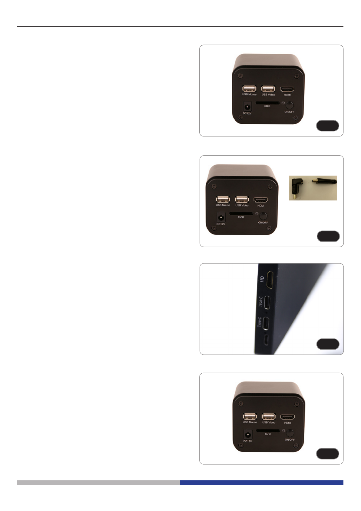
1. Plug the HDMI cable into the HDMI port ③ to connect the C-HP4 camera to HDMI display.
2. Plug the USB mouse into USB Mouse port ① to get control of the camera by using built-in software HDMI pro.
3. Plug 12V/1A power adapter into DC 12V slot ⑥ to supply power for the camera. The LED Indicator ⑦ will turn into red.
4. Insert SD card into SD Card slot ⑤ for saving captured images and recorded videos.
5. Press ON/OFF Button ④ to turn on the camera. The LED indicator will turn into blue.
6. Move mouse cursor to the left side of the video window, a Camera Control Panel will appear. It includes Manual/ Auto-
matic Exposure, White Balance, Sharpness and other functions, please refer to 10.1 for details.
7. Move mouse cursor to the bottom of the video window and a Camera Control Toolbar will appear. Operations like Zoom
In, Zoom Out, Flip, Freeze, Cross Line, Comparison and so on can be achieved. Please refer to 10.3 for details.
8. Move mouse cursor to the upper side of the video window, a Measurement Toolbar with calibration and other measure-
ment tools will appear, please refer to 10.2 for details. The measurement data can be output with *.CSV format.
9.1.2 USB Mode
1. Plug the USB cable provided with the camera into USB2.0 ② to connect the C-HP4 camera to the computer.
2. Plug 12V/1A power adapter into DC 12V slot ⑥ to supply power for the camera. The LED Indicator ⑦ will turn into red.
3. Press ON/OFF button ④ to turn on the camera. The LED indicator will turn into blue.
4. Start the ProView software.
5. Clicking the camera name in the camera list starts the live video.
• NOTE:WhentheUSBcableandthemousearepluggedintothecameraatthesametime,theUSBcablehas
priorityandthemouseisnotavailable;whentheUSBcableisunplugged,themousecanbeusednormally.

Page 11
10. C-HP4 User Interface (UI) and its Functions
The C-HP4 UI shown in Fig. 12 includes a Camera Control Panel on the left side of the video window, a Measurement Tool-
bar on the upper side of the video window, a Camera Control Toolbar on the bottom of the video window.
Fig. 12 - Camera Control User Interface
1. Move the mouse cursor to the left side of the video window: the Camera Control Panel will pop up automatically.
2. Move the mouse cursor to the upper side of the video window: a Measurement Toolbar will pop up for the calibration
and measurement operations.
• When user left-clicks the Float/Fixed button on the Measurement Toolbar, the Measurement Toolbar will be xed. In
this case the Camera Control Panel will not pop up automatically even if users move mouse cursor to left side of the
video windows.
• Only when user left-clicks the button on the Measurement Toolbar to exit from measuring procedure it will be possi-
ble to perform other operations on the Camera Control Panel, or Camera Control Toolbar.
• During the measuring process, when a specic measuring object is selected an Object Location & Attributes Control Bar
will appear for changing location and properties of the selected objects.
3. Move the mouse cursor to the bottom of the video window, the Camera Control Toolbar will pop up automatically.

Page 12
10.1 The Camera Control Panel
The Camera Control Panel controls the camera to achieve the best image quality according to the specic applications.
It will pop up automatically when mouse cursor is moved to the left side of the video window (in measurement status, the
Camera Control Panel will not pop up. Only when measurement process is terminated the Camera Control Panel will pop
up by moving mouse cursor to the left side of the video window).
Left-clicking button to achieve Display/ Auto Hide switch of the Camera Control Panel.
Control Panel Function Description
Snap Capture image from the current video window
Record Record video from the current video window
Auto Exposure When Auto Exposure is checked, the system will automatically adjust ex-
posure time according to the value of exposure compensation
Exposure
Compensation
Available when Auto Exposure is checked. Slide to left or right to adjust
Exposure Compensation according to the current video brightness to
achieve proper brightness value
Exposure Time Available when Auto Exposure is unchecked. Slide to left or right to re-
duce or increase exposure time, adjusting brightness of the video
Gain Adjust Gain to reduce or increase brightness of video. The Noise will be
reduced or increased accordingly
Auto White
Balance White Balance adjustment according to the window video every time the
button is clicked
Manual White
Balance Slide Red or Blue cursors to manually set the video White Balance
ROI White
Balance When the ROI region is moved, white Balance can be adjusted according
to content inside the ROI region.
Red Slide to left or right to decrease or increase the proportion of Red in RGB
on video
Green Slide to left or right to decrease or increase the proportion of Green in
RGB on video
Blue Slide to left or right to decrease or increase the proportion of Blue in RGB
on the video
Sharpness Adjust Sharpness level of the video window
Denoise Slide left or right to denoise the image
Saturation Adjust Saturation level of the video window
Gamma Adjust Gamma level of the video. Slide to the right side to increase gam-
ma and to the left to decrease gamma
Contrast Adjust Contrast level of the video. Slide to the right side to increase con-
trast and to the left to decrease contrast
DC For DC illumination, there will be no uctuation in light source so no need
for compensating light ickering
AC(50HZ) Check AC(50HZ) to eliminate ickering “strap” caused by 50Hz illumina-
tion
AC(60HZ) Check AC(60HZ) to eliminate ickering “strap” caused by 60Hz illumina-
tion
Default Restore all the settings in the Camera Control Panel to default values

Page 13
10.2 The Measurement Toolbar
The Measurement Toolbar will pop up when moving mouse cursor to any place near the upper side of the video window.
Fig. 13 - The Measurement Toolbar
Icon Function
Float/ Fix switch of the Measurement Toolbar
Dene measuring object in Show up/ Hide mode
Select the desired Measurement Unit
Select Magnication for Measurement after Calibration
Object Select
Angle
4 Points Angle
Point
Arbitrary Line
3 Points Line
Horizontal Line
Vertical Line
3 Points Vertical line
Parallel
Rectangle
Ellipse
5 Points Ellipse
Circle
3 Points Circle
Annulus
Two Circles and Center Distance
3 Points Two Circles and Center Distance
Arc
Text

Page 14
Polygon
Curve
Scale Bar
Arrow
Execute Calibration to determine the corresponding relation between magnication and resolution,
which will establish the corresponding relationship between measurement unit and the sensor pixel
size. Calibration needs to be done with the help of a micrometer. For detailed steps of carrying out
Calibration please refer to chapter 10.3.
Export the Measurement to CSV le(*.csv)
Measurement Setup
Delete All the Measurement Objects
Exit from Measurement mode
When the measurement ends, left-click on a single measuring object and the Object Location & Prop-
erties Control Bar will show up. User could move the object by dragging the object with the mouse.
But more accurate movement could be done with the control bar. The icons on the control bar mean
Move Left, Move Right, Move Up, Move Down, Color Adjustment and Delete.
Note:
1. When user left-clicks Display/Hide button on the Measurement Toolbar, it will be xed. In this case the Camera
Control Panel will not pop up automatically even if moving the mouse cursor to the left edge of the video window. Only
when user left-click the button on the Measurement Toolbar to exit from the measurement mode it will be possible to
perform other operations on the Camera Control Panel or on the Camera Control Toolbar.
2. When a specic item is selected during the measurement process, the Object Location & Attributes Control Bar
will appear for changing the object location and properties of the selected objects.

Page 15
10.3 Camera calibration
The camera must be calibrated before any measurements can be taken.
To do this it is necessary to use the micrometer slide supplied with the camera.
Detailed procedure is the following:
1. Insert the objective with the lowest magnication available and put the stage micrometer on the stage.
2. Click on the “Calibrate” button in the Measurement toolbar.
3. The following dialog box appears:
4. In the Magnication eld enter the current magnication
• Some magnication values (default ones 4x, 10x, 20x, 40x and 100x) are preset in the drop-down list.
• If user must insert a dierent magnication value, double click in the Magnication eld. The following dialog box ap-
pears:
• From here user can enter any desired magnication value.
5. Focus the ruler under the microscope.
• Along with the previous dialog box a red line appears on the image. This line is the calibration line.

Page 16
6. Align the two ends of the red line with the ruler scale (try to use as many notches as possible to keep the calibration
accuracy).
7. Set the desired unit (micrometer, millimeter or nanometer) in the Calibration dialog box.
8. Insert the length of the drawn line in the Actual Length eld (using the same procedure described above).
• Micrometric slide has two rulers (see chapter 11). One is 1 mm/100 (for biological microscopes) and the other is
10mm/100 (for stereomicroscopes).
• When using the ruler 1mm/100 the interval between two long lines is 100 mm, while using the ruler 10mm/100 the inter-
val between two long lines is 1000 mm.
9. If everything is ne, click OK to end the calibration. The new magnication (the number you entered in the Magnication
edit box) will be available in the Magnication drop-down list.
10. Repeat the same procedure for each magnication available in your microscope.

Page 17
10.4 Icons and Functions of the Camera Control Toolbar
Icon Function Icon Function
Zoom In the Video Window Zoom Out the Video Window
Horizontal Flip Vertical Flip
Color / Gray Video Freeze
Display Cross Line Overlay
Compare stored image with the current live
image Browse Images and Videos in the SD Card
Settings Check the HDMI pro Version
The Setting function is relatively more complicated than the other functions. Here are more info about it:
10.4.1 Setting > Measurement
Fig. 14 - Measurement Setting Page
Global Used for setting digits behind the decimal point for measurement results
Calibration Line Width Used for dening width of the lines for calibration
Color Used for dening color of the lines for calibration
EndPoint Type: Used for dening shape of the endpoints of lines for calibration
Null: Means no endpoints
Rectangle: Means rectangle type of endpoints. It makes alignment more easily
Point, Angle, Line, Horizontal Line, Vertical Line, Rectangle, Circle, Ellipse, Annulus, Two Circles, Polygon, Curve:
Left-click the beside the measuring patterns mentioned above will unfold the corresponding attribute settings to set the
individual property of the measuring objects

Page 18
10.4.2 Setting>Magnication
Fig. 15 - Magnication Settings Page
Name
Names 10X, 40X, 100X are based on magnication of the microscopes. For continuous zoom micro-
scopes, ensure that the selected magnication coincides with the scale alignment line on the zoom knob
Resolution Pixels per meter. Devices like microscopes have high resolution value
Clear All Click the Clear All button will clear the calibrated magnications and resolutions
Delete Click Delete to delete the selected item for specic resolution
Up Click Move Up to move up the selected Magnication
Down Click Move Down to move down the selected Magnication
10.4.3 Setting > Image Format
Fig. 16 - Image Format Settings Page
Image Format JPEG A JPEG le can get very high compression rate and display very rich and vivid images
by removing redundant images and color data. In other words, it can get better image
quality with the least disk space. If measurement objects are available, the measurement
objects will be burned into the image and the measurement cannot be edited
TIFF TIFF is a bitmap format mainly used to store images including photos and artistic images
Measurement
Object Save
Method
Burn in
Mode The measurement objects are merged into the current image. User could not edit the
measurement objects anymore. This mode is not reversable
Layered
Mode The measurement objects are saved in dierent layer with current image data in the tar-
get le. User could edit the measurement objects in the target le with some software on
the PC. This mode is reversable

Page 19
10.4.4 Setting > Video
Fig. 17a - Video Settings Page - Playback
Fig. 17b - Video Settings Page - Video Encode
Fast Forward/
Reverse interval The time interval in second units for Video Playback
Video Encode You can choose H264 or H265 encoding. H265 encoding can signicantly reduce encoding bandwidth
and save storage space under the same encoding quality.

Page 20
10.4.5 Setting > Storage
Fig. 18 - SD Card Settings Page
Storage Device SD Card: only SD Card is supported as the storage device
File System
Format of the
Storage Device
List the le system format of the current storage device
FAT32 The le system of SD card is FAT32. The maximum le size of single le is 4GB
exFAT The le system of SD card is exFAT. The maximum le size of single le is 4GB
NTFS The le system of SD card is NTFS. The maximum le size of single le is 4GB
Unknown
Status SD card not detected or the le system is not identied
Use PC to format the SD Card and switch between FAT32, exFat and NTFS
10.4.6 Setting > Files
Fig. 19 - Files Settings Page
Image File Name Auto: The image les will be saved automatically with the specied prex
Manual: User has to specify the Image le name before image saving
Video File Name Auto: The video le will be saved automatically with the specied prex
Manual: User has to specify the Video File Name before video recording
This manual suits for next models
2
Table of contents
Languages:
Other Optika Italy Digital Camera manuals

Optika Italy
Optika Italy H Series User manual

Optika Italy
Optika Italy H Series User manual

Optika Italy
Optika Italy C-HA User manual

Optika Italy
Optika Italy SZP Series User manual

Optika Italy
Optika Italy H Series User manual

Optika Italy
Optika Italy OPTIKAM B1 User manual

Optika Italy
Optika Italy H Series User manual

Optika Italy
Optika Italy C-D Series User manual

Optika Italy
Optika Italy H Series User manual

Optika Italy
Optika Italy C-B Series User manual