Optika Italy H Series User manual

Model
C-HP
HDMI Cameras – H Series
INSTRUCTION MANUAL
v 1.0 2018

Contents
C-HP
C-mount HDMI+USB CMOS Camera
Instruction Manual
1 C.HP Basic Characteristics
1.1 USB Video Mode
1.2 HDMI MODE.
2 Brief Introduction of C-HP UI and Its Functions
2.1 The Camera Control Panel on the Left Side of the Video Window
2.2 Icons and Functions of the Camera Control Toolbar at the Bottom of the Video Window
2.3 The Measurement Toolbar on the Upper Side of the Video Window

1C.HP Basic Characteristics
C-HP is a multiple interfaces (HDMI + USB2.0 + SD card) CMOS camera. HDMI + USB2.0 are used as the data transfer
interface to HDMI display or computer.
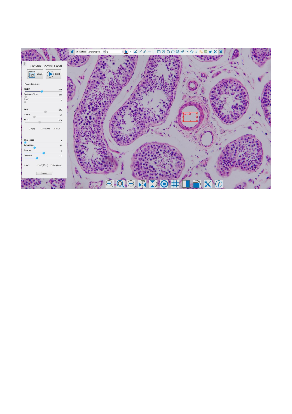
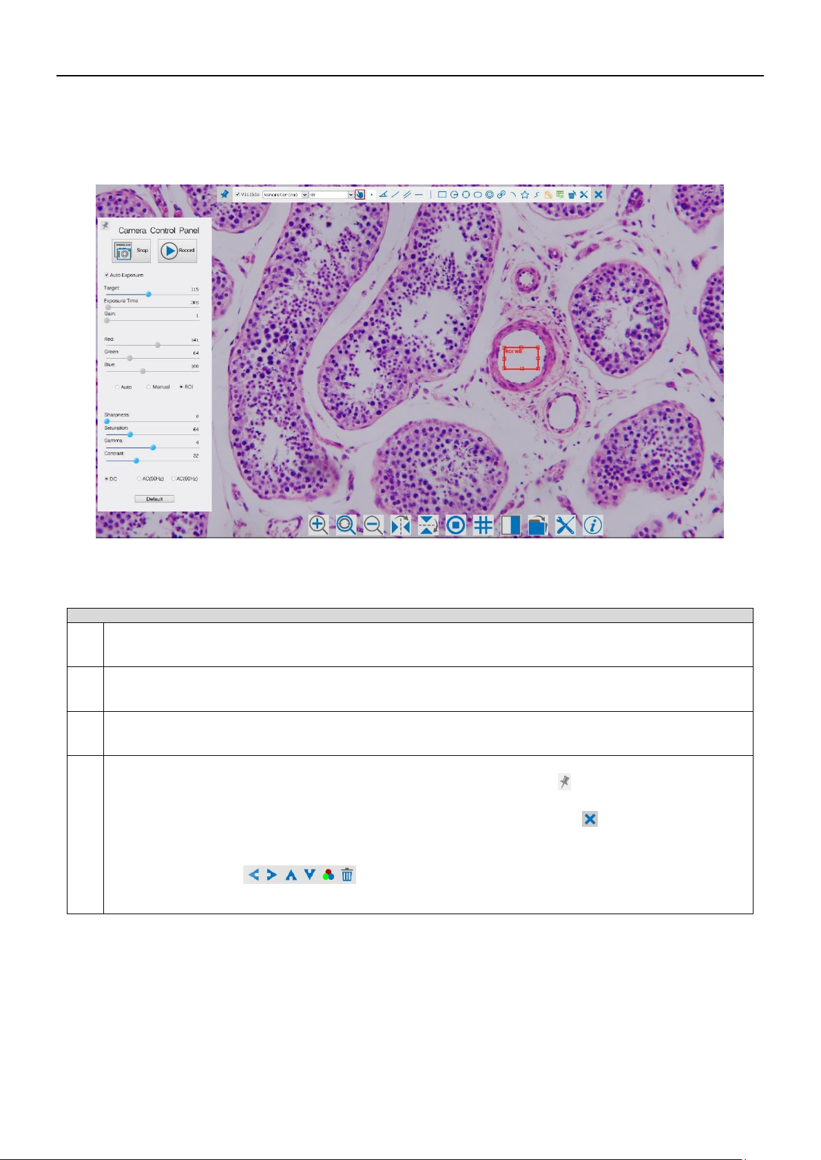
For HDMI output, the Camera Control Panel+ Measurement Toolbar and Camera Control Toolbar are overlaid on the HDMI screen when
the mouse move to the related region, in this case, the USB mouse can be used to set the camera, browse and compare
the captured image, play the video and perform the measurement ital.
For USB Video camera mode, plug in the micro USB host cable to the camera USB video port and computer USB port, then
the video stream can be transfer to computer with the advanced software ProView. With ProView, you can control the
camera, process the video and image as OPTIKA's other USB series camera.
The C-HP’s basic characteristics are as follows:
For HDMI output:
All in 1(HDMI + USB + SD card) C-mount camera with Sony high sensitivity CMOS sensor;
Simultaneous HDMI & USB output;
Built-in mouse control;
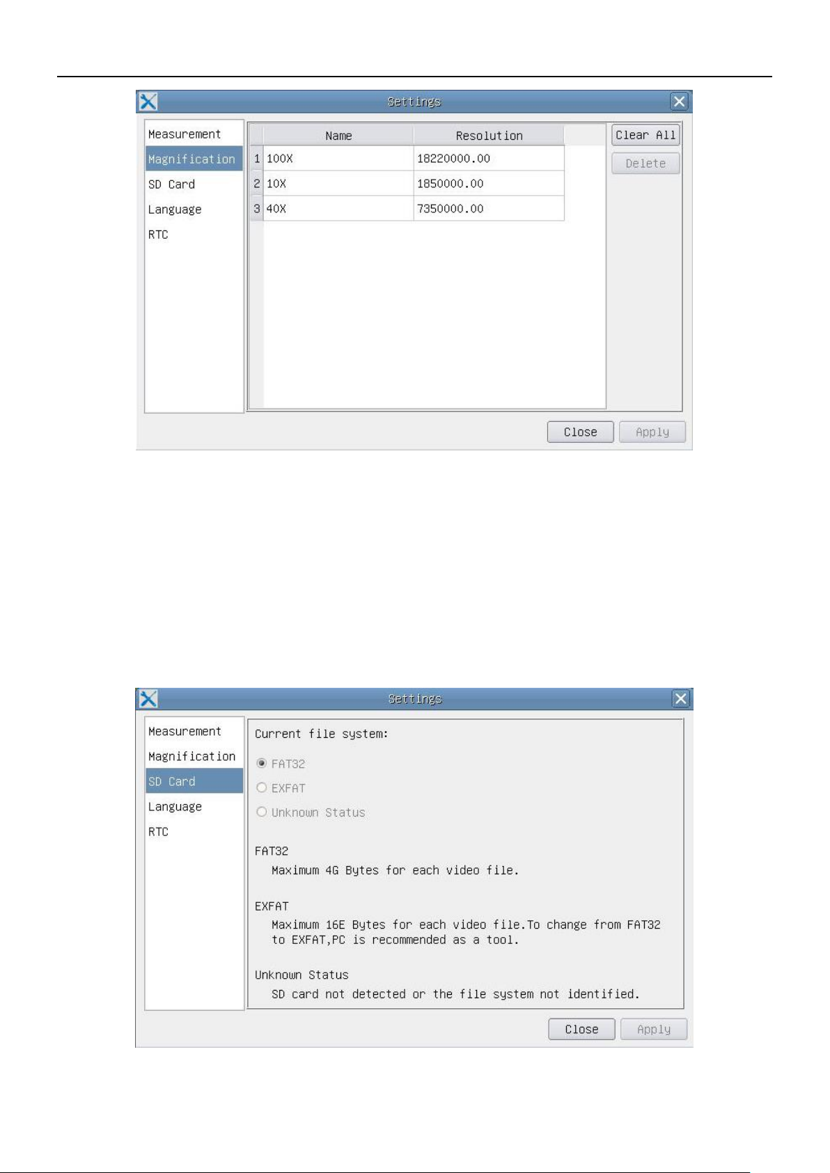
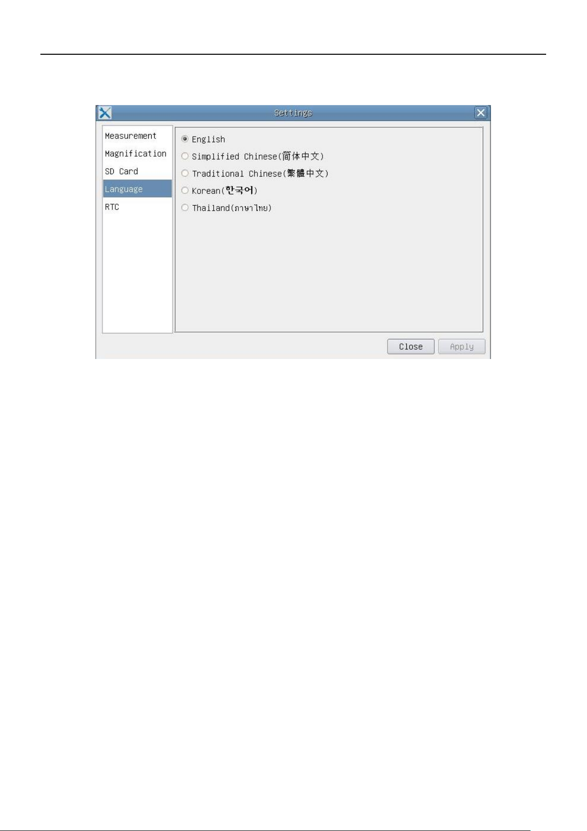
Built-in image capture & video record to SD card;
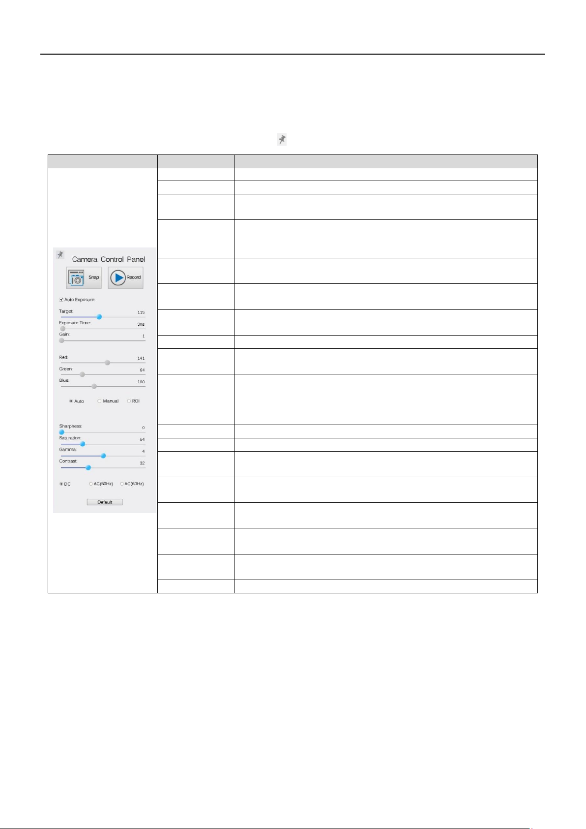
Built-in camera control panel, including exposure(manual/auto)/gain, white balance(lockable), color
adjustment, sharpness control;
Built-in video and image measurement;
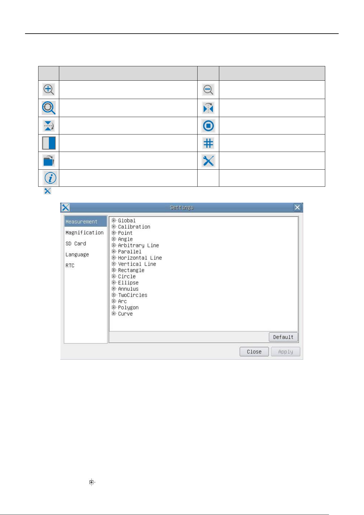
Built-in toolbar including zoom, mirror, comparison, freeze, cross, browser functions;
Built-in image & video browsing, display & play;
Real time clock(RTC)
For USB Video output:
Ultra-Fine color engine with perfect color reproduction capability(USB);
With advanced video & image processing application ProView, which including professional image processing
such as 2D measurement, HDR, image stitching, EDF(Extended Depth of Focus), image segmentation & count,
image stacking, color composite and denoising (USB);
Support standard UVC protocol for Windows/Linux/Mac(USB);

C-HP - Microscope + Display
C-HP - SW UI for Mouse Control

Quick Instructions for C-HP camera
Figure 1 - The Layout of C-HP Rear Cover
Before starting the camera, please connect the standard C-HP C-mount camera to the camera adapter and insert it into
the microscope’s 3rd photo tube which will relay microscope object’s middle image to the camera sensor.
1.1 USB Video Mode
1. Plug 12V/ 1A power cable into DC 12V slot to supply power for the camera. The LED Indicator will turn into red;
2. Press ON/OFF Button to start the camera and the LED Indicator will turn into blue;
3. Plug the USB cable which comes with the camera into USB Video to connect the video to the computer;
4. Open ProView software, start C-HP by clicking the camera model name listed in Camera List. For more details please refer to
the ProView help manual;
1.2 HDMI MODE
1. Plug the HDMI cable into the HDMI Port to connect the C-HP camera to HDMI display;
2. Plug a USB mouse into USB Mouse to get control of the camera by using built-in software ProView;
3. Plug 12V/ 1A power adapter into Power Interface to supply power for the camera. The LED Indicator will turn into red;
4. Insert SD card into SD Card Slot for saving captured images and recorded videos;
5. Press ON/ OFF Buttonto start the camera. The LED Indicator will turn into blue;
6. Move mouse cursor to the left side of the video window, a Camera Control Panel will appear. It includes Manual/ Automatic Exposure,
White Balance, Sharpness and other functions, please refer to2.1 for details;
7. Move mouse cursor to the bottom of the video window and a Camera Control Toolbar will appear. Operations like Zoom In,
Zoom Out, Flip, Freeze, Cross Line, Comparison and etc. can be realized. Please refer to 2.2 for details;
8. Move mouse cursor to the upper side of the video window, a Measurement Toolbar with calibration and other
measurement tools will appear, please refer to 2.3 for details; The measurement data can be output with *.CSV format.

2Brief Introduction of C-HP UI and Its Functions
The C-HP UI shown in Fig. 2 includes a Camera Control Panel on the left side of the video window, a Measurement Toolbar on the upper
side of the video window, a Camera Control Toolbar on the bottom of the video window.
Figure 2 - The C-HP Camera Control UI
Notes
1
When users move mouse cursor to the left side of the video window, the Camera Control Panel will pop up
automatically;
2
When users move mouse cursor to the bottom of the video window, the Camera Control Toolbar will pop up
automatically;
3
When user moves mouse cursor to the bottom of the video window, the Camera Control Toolbar will pop up
automatically.
4
Move the mouse cursor to the upper side of the video window, a Measurement Toolbar will pop up for the calibration
and measurement operations. When user left-clicks the Float/Fixed button on the Measurement Toolbar, the
Measurement Toolbar will be fixed. In this case the Camera Control Panel will not pop up automatically even if users move
mouse cursor to left side of the video windows. Only when user left-clicks the button on the Measurement
Toolbar to exit from measuring procedure will they be able to do other operations on the Camera Control Panel, or
Synthesis Camera Control Toolbar. During the measuring process, when a specific measuring object is selected an Object
Location & Attributes Control Bar will appear for changing location and properties of the selected
objects.

2.1 The Camera Control Panel on the Left Side of the Video Window
The Camera Control Panel controls the camera to achieve the best image quality according to the specific applications; It will
pop up automatically when mouse cursor is moved to the left side of the video window (in measurement status, the Camera
Control Panel will not pop up. Only when measurement process is terminated will the Camera Control Panel pop up by moving mouse
cursor to the left side of the video window). Left-clicking button to achieve Display/ Auto Hide switch of the Camera Control Panel;
Camera Control Panel
Function
Function Description
Snap
Capture image from the current video window
Record
Record video from the current video window
Auto Exposure
When Auto Exposure is checked, the system will automatically adjust
exposure time according to the value of exposure compensation
Target
Available when Auto Exposure is checked. Slide to left or right to adjust
Target according to the current video brightness to achieve proper
brightness value
Exposure Time
Available when Auto Exposure is unchecked. Slide to left or right to reduce
or increase exposure time, adjusting brightness of the video
Gain
Adjust Gain to reduce or increase brightness of video. The Noise will be
reduced or increased accordingly
Red
Slide to left or right to decrease or increase the proportion of Red in
RGB on video
Green
Green is base for reference and cannot be adjusted
Blue
Slide to left or right to decrease or increase the proportion of Blue in
RGB on the video
White Balance
Auto: White Balance adjustment according to the window video;
Manual: Slide the Red or Blue to manually set the video White Balance;
ROI: Set the White Balance according to the ROI. The ROI can be resized and
moved;
Sharpness
Adjust Sharpness level of the video window
Saturation
Adjust Saturation level of the video window
Gamma
Adjust Gamma level of the video. Slide to the right side to increase
gamma and to the left to decrease gamma.
Contrast
Adjust Contrast level of the video. Slide to the right side to increase
contrast and to the left to decrease contrast.
DC
For DC illumination, there will be no fluctuation in light source so no
need for compensating light flickering
AC(50HZ)
Check AC(50HZ) to eliminate flickering “strap” caused by 50Hz
illumination
AC(60HZ)
Check AC(60HZ) to eliminate flickering “strap” caused by 60Hz
illumination
Default
Set all the settings in the Camera Control Panel to default values

2.2 Icons and Functions of the Camera Control Toolbar at the Bottom of
the Video Window
Icon
Function
Icon
Function
Zoom In the Video Window
Zoom Out the Video Window
Reset Zoom to Original 1X
Horizontal Flip
Vertical Flip
Video Freeze
Compare Image with the current video
Display Cross Line
Browse Images and Videos in the SD Card
Settings
Check the Version of ProView
The Setting function is relatively more complicated than the other functions. Here are more info about it:
Figure 3 - Comprehensive Measurement Settings Page
Global:Used for setting digits behind the decimal point for measurement results;
Calibration LineWidth:Used for defining width of the lines for calibration;
Color: Used for defining color of the lines for calibration;
EndPoint Type: Used for defining shape of the endpoints of lines for calibration: Null means no
endpoints, rectangle means rectangle type of endpoints. It makes alignment more
easily;
Point,Angle,Line,HorizontalLine,VerticalLine,Rectangle,Circle,Ellipse,Annulus,TwoCircles,Polygon,Curve:
Left-click the besides the measuring patterns mentioned above will unfold the corresponding
attribute settings to set the individual property of the measuring objects.

Figure 4 - Comprehensive Magnification Calibration Management Settings Page
Name: Names such as 10X, 40X, 100X are based on magnification of the microscopes. For continuous zoom
microscopes, ensure that the selected magnification coincides with the scale alignment line on the
microscope zoom knob;
Resolution: Pixels per meter. Devices like microscopes have high resolution value;
ClearAll: Click the ClearAllbutton will clear the calibrated magnifications and resolutions;
Delete: Click Delete to delete the selected item for specific resolution;
Figure 5 - Comprehensive Setting of SD Card Setting Page

CurrentFileSystem: The maximum file FAT32 can store is of 4G Bytes; for EXFAT, it’s 2048G Bytes. Suggest converting FAT32
file into EXFAT format on a PC; UnknownStatus: SD card not detected or the file system is not identified;
Figure 6 - C-HP Comprehensive Setting of Language Selection Setting Page
English:Set language of the whole software into English;
SimplifiedChinese:Set language of the whole software into Simplified Chinese;
TraditionalChinese:Set language of the whole software into Traditional Chinese;
Korean: Set language of the whole software into Korean;
Thailand: Set language of the whole software into Thailand;

Figure 7 - The Real Time Clock Setting
Year: Current Year
Month: Current Month
Day: Current Day
Hour: Current Hour
Minute: Current Minute
Second: Current Second

2.3 The Measurement Toolbar on the Upper Side of the Video Window
The Measurement Toolbar will pop up when moving mouse cursor to any place near the upper side of the video window. Here
are the introduction of the various functions on the Measurement Toolbar:
Figure 8 - The Measurement Toolbar Button on the Upper Side of the Video window
Icon
Function
Float/ Fix switch of the Measurement Toolbar
Define measuring object in Show up/ Hide mode
Select the desired Measurement Unit
Choose the same Magnification as the microscope to ensure accuracy of measurement
result when measurement unit is not in Pixel unite
Object Select
Point
Angle
Arbitrary Line
Parallel
Horizontal Line
Vertical Line
Rectangle
Circle
Ellipse
Annulus
Two Circles and Center Distance
Arc
Polygon
Curve
Make Calibration to determine the corresponding relation between magnification and resolution, this will establish the
corresponding relationship between measurement unit and the sensor pixel size. Calibration needs to be done with the help of a
micrometer. For detailed steps of carrying out calibration please refer to ProView help manual.
Export the measurement information to CSV file(*.csv)
Delete All the Measurement Objects
Setting

Exit from Current Measurement Mode
When the measurement ends, left-click on a single measuring object and the Object Location & Properties
Control Bar will show up. The icons on the control bar mean Move Left, Move Right, Move Up, Move Down, Color
Adjustment and Delete.
Note:
1) When user left-clicks Display/Hide button on the Measurement Toolbar, the Measurement Toolbar will be fixed. In this case the
Camera Control Panel will not pop up automatically even if moving mouse cursor to the left side of the video window. Only when
users left click the button on the Measurement Toolbar to exit from the measurement mode will they be able to doing other
operations in the Camera Control Panel, the Auto Focus Control Panel or the Synthesis Camera Control Toolbar.
2) When a specific measuring object is selected during the measuring process, the Object Location & Attributes Control Bar
will appear for changing the object location and properties of the selected objects

Modello
C-HP
Telecamere HDMI – Serie H
MANUALE D’ISTRUZIONI
v 1.0 2018

Sommario
C-HP
Telecamera CMOS con passo “C” HDMI+USB
Manuale di lstruzioni
1 C-HP Caratteristiche Principali
1.1 Modalità Video USB
1.2 Modalità HDMI
2 Breve introduzione all’interfaccia Utente della C-HP e sue funzioni
2.1 Il Pannello di Controllo Camera sul lato sinistro del monitor
2.2 Icone e Funzioni Della Barra degli Strumenti Controllo Camera nella perte inferiore del monitor
2.3 La Barra degli Strumenti Misurazioni nella parte superiore del monitor

1C-HP - Caratteristiche Principali
La C-HP è una telecamera CMOS ad interfaccia multipla (HDMI + USB2.0 + SD card). HDMI e USB2.0 vengono
usati come interfaccia trasferimento dati ad un monitor HDMI o ad un computer.
Nell’interfaccia HDMI, il Pannello di Controllo Telecamera + Barra degli strumenti Misurazione e la Barra degli strumenti Controllo Camera sono
in sovraimpressione sul monitor HDMI quando il mouse si sposta sulla zona del monitor corrispondente; in questo
caso il mouse USB viene usato per impostare i parametri della telecamera, navigare e confrontare le immagini
acquisite, riprodurre video, ed eseguire misurazioni.
Nell’interfaccia USB Video, collegare il cavo micro USB nel connettore USB video posto sul pannello della telecamera
e in una porta USB del computer; a questo punto l’immagine verrà trasferita al computer tramite il software
ProView. Con ProView, si potrà controllare la telecamera, elaborare video ed immagini esattamente come per tutte
le altre telecamere della serie di OPTIKA.
Le caratteristiche principali della C-HP sono le seguenti:
Per l’interfaccia HDMI:
Telecamera passo “C” (HDMI + USB + SD card) con sensore Sony CMOS ad alta sensibilità;
Uscita contemporanea HDMI & USB;
Controllo via mouse integrato;
Controllo integrato di cattura immagine e video su SD card;
Pannello di controllo della telecamera incorporato, che include controllo di esposizione
(manuale/auto)/guadagno, bilanciamento del bianco (bloccabile), regolazione colori, nitidezza;
Misurazione su immagini e video integrato;
Barra degli strumenti integrata che include zoom, ribaltamento immagine, confronto, freeze, croce,
funzioni di ricerca immagine;
Ricerca, visualizzazione e riproduzione di immagini e video integrata;
Orologio in tempo reale(RTC)
Per l’interfaccia USB Video:
Motore a colori Ultra-fine con perfetta capacità di riproduzione del colore (USB);
Software di elaborazione per immagini e video ProView, che incorpora elaborazioni professionali quali
misurazioni 2D, HDR, composizione immagini, EDF (Extended Depth of Focus), segmentazione e conta di
immagini, sovrapposizione immagini, composizione colori e denoising (USB);
Supporta protocolli UVC standard per Windows/Linux/Mac(USB);

C-HP - Visualizzazione da microscopio
C-HP - Software Interfaccia Utente per Controllo via Mouse

Istruzioni rapide per la telecamera C-HP
Figura 9 – Pannello posteriore della C-HP
Prima di accendere la telecamera, collegare l’adattatore passo “C” alla telecamera e inserire l’adattatore sulla
porta trinoculare del microscopio.
1.1 Modalità Video USB
5. Collegare il cavo di alimentazione 12V/ 1A nel connettore DC 12V per alimentare la camera. Il LED Indicator diventerà
rosso;
6. Premere il tasto ON/OFF per accendere la camera; il LED Indicator diventerà blu;
7. Collegare il cavo USB in dotazione con la camera nella porta USB Video per collegare l’uscita video al computer;
8. Avviare il software ProView, attivare C-HP cliccando il nome della telecamera nell’elenco Camera List. Per maggiori
dettagli consultare il manuale di istruzioni di ProView;
1.2 Modalità HDMI
9. Collegare il cavo HDMI nella porta HDMI per collegare la camera C-HP al monitor HDMI;
10. Collegare il mouse USB nella porta USB Mouse per ottenere il controllo della camera mediante il software
integrato ProView;
11. Collegare il cavo di alimentazione 12V/ 1A nel connettore DC 12V per alimentare la camera. Il LED Indicator diventerà
rosso;
12. Inserire la scheda SD nella fessura SD per salvare immagini e video acquisiti;
13. Premere il tasto ON/OFF per accendere la camera; il LED Indicator diventerà blu;
14. Muovere il cursore del mouse sul lato sinistro della finestra video; apparirà il Pannello di Controllo Camera. Include
Manual/ Automatic Exposure, White Balance, Sharpness ed altre funzioni, consultare il paragrafo 2.1 per maggiori dettagli;
15. Muovere il cursore del mouse sulla parte bassa della finestra video e apparirà una Barra degli Strumenti Controllo Camera.
Sono possibili operazioni quali Zoom In, Zoom Out, Flip, Freeze, Cross Line, Comparison ed altre. Consultare il paragrafo 2.2
per maggiori dettagli;
16. Muovere il cursore del mouse sulla parte alta della finestra video; apparirà una Barra degli Strumenti Misurazioni con
funzioni di calibrazione e di altri strumenti di misura, consultare il paragrafo 2.3 per maggiori dettagli. I dati
delle misurazioni possono essere esportati con formato *.CSV.

2Breve introduzione all’interfaccia Utente della
C-HP e sue funzioni
L’Interfaccia Utente C-HP mostrata in Fig. 2 include un Pannello di Controllo Camera sul lato sinistro del video, una Barra degli
Strumenti Misurazioni nella parte alta del video ed una Barra degli Strumenti Controllo Camera nella parte inferiore.
Figura 10 – L’Interfaccia Utente del Controllo Camera C-HP
Note
1
Quando si sposta il cursore verso la parte sinistra del monitor, il Pannello di Controllo Camera si attiva
automaticamente;
2
Quando si sposta il cursore verso la parte bassa del monitor, la Barra degli Strumenti Controllo Camera si attiva
automaticamente;
3
Quando si sposta il cursore verso la parte alta del monitor, la Barra degli Strumenti Controllo Camera si attiva
automaticamente.
4
Spostare il cursore verso la parte alta del monitor, una Barra degli Strumenti Misurazioni si attiva per le operazioni di
calibrazione e di misurazioni. Quando si clicca con il tasto sinistro del mouse sul tasto Blocca/Nascondi sulla Barra
degli Strumenti Misurazioni, questa verrà bloccata. In questo caso il Pannello di Controllo Camera non si attiva automaticamente
anche quando l’operatore sposta il cursore sul lato sinistro del monitor. Solo quando l’operatore clicca sul
tasto sulla Barra degli Strumenti Misurazioni per abbandonare la sessione di misurazioni, sarà possibile effettuare
altre operazioni sul Pannello di Controllo Camera, o sulla Barra degli Strumenti Controllo Camera. Durante il processo di misurazioni,
quando uno specifico oggetto di misura è selezionato una Barra di Controllo Posizione Oggetto & Attributi
appare per modificare la posizione e le proprietà degli oggetti selezionati.

2.1 Il Pannello di Controllo Camera sul lato sinistro del monitor
Il Pannello di Controllo Camera controlla la camera per ottenere la migliore qualità dell’immagine in funzione
dell’applicazione specifica. Appare automaticamente quando il cursore del mouse viene spostato nella parte
sinistra del monitor (durante la sessione di misura il Pannello di Controllo Camera non si attiva. Solo quando la sessione di
misura è terminata il Pannello di Controllo Camera si attiva muovendo il cursore del nella parte sinistra del monitor). Fare
doppio clic sul tasto per attivare la funzione Mostra/Nascondi Automaticamente del Pannello di Controllo Camera;
Pannello di Controllo
Camera
Funzione
Descrizione Funzione
Snap
Cattura l’immagine attualmente visualizzata sul monitor
Record
Registra un video dalla videata attualmente mostrata sul monitor
Auto Exposure
Quando Auto Exposure è attivato, il sistema adatta automaticamente il
tempo di esposizione in funzione del valore di compensazione
esposizione
Target
Attivo quando Auto Exposure è attivato. Spostare a destra o a sinistra per
adattare il Target alla luminosità attuale del monitor per ottenere il
valore ottimale di luminosità
Exposure Time
Attivo quando Auto Exposure è disattivato. Spostare a sinistra o a destra
per ridurre o aumentare il tempo di esposizione, regolando la
luminosità a monitor
Gain
Regolare il Gain (Guadagno) per ridurre o aumentare la luminosità a
monitor. Il rumore verrà ridotto o aumentato di conseguenza
Red
Spostare a sinistra o a destra per ridurre o aumentare il valore del
Rosso in RGB sul monitor
Green
Verde è la base di riferimento e non può essere regolato
Blue
Spostare a sinistra o a destra per ridurre o aumentare il valore del Blu
in RGB sul monitor
White Balance
Auto:regolazione del Bilanciamento del Bianco in base alla visualizzazione a
monitor;
Manual: Spostare il Red o il Blue per impostare manualmente il Bilanciamento
del Bianco;
ROI: Imposta il Bilanciamento del Bianco in funzione della ROI (Region Of Interest). La
ROI può essere ridimensionata e spostata;
Sharpness
Regola il livello di Nitidezza visualizzato a monitor
Saturation
Regola il livello di Saturazione visualizzato a monitor
Gamma
Regola il livello di Gamma visualizzato a monitor. Spostare a destra per
aumentare e a sinistra per diminuire il gamma.
Contrast
Regola il livello di Contrasto visualizzato a monitor. Spostare a destra per
aumentare e a sinistra per diminuire il contrasto.
DC
Per l’illuminazione DC, non ci sono fluttuazioni nella sorgente
luminosa quindi non sono necessarie compensazioni per lo sfarfallio
della luce
AC(50HZ)
Abilitare AC(50HZ) per eliminare lo sfarfallio della luce causato da
illuminazione a 50Hz
AC(60HZ)
Abilitare AC(60HZ) per eliminare lo sfarfallio della luce causato da
illuminazione a 60Hz
Default
Riporta tutti i valori impostati nel Pannello di Controllo Camera ai valori di
default
Other manuals for H Series
4
This manual suits for next models
1
Table of contents
Languages:
Other Optika Italy Digital Camera manuals

Optika Italy
Optika Italy H Series User manual

Optika Italy
Optika Italy H Series User manual

Optika Italy
Optika Italy H Series User manual

Optika Italy
Optika Italy SZP Series User manual

Optika Italy
Optika Italy C-HP4SC User manual

Optika Italy
Optika Italy C-HA User manual

Optika Italy
Optika Italy H Series User manual

Optika Italy
Optika Italy C-B Series User manual

Optika Italy
Optika Italy OPTIKAM B1 User manual

Optika Italy
Optika Italy C-D Series User manual