Page 8
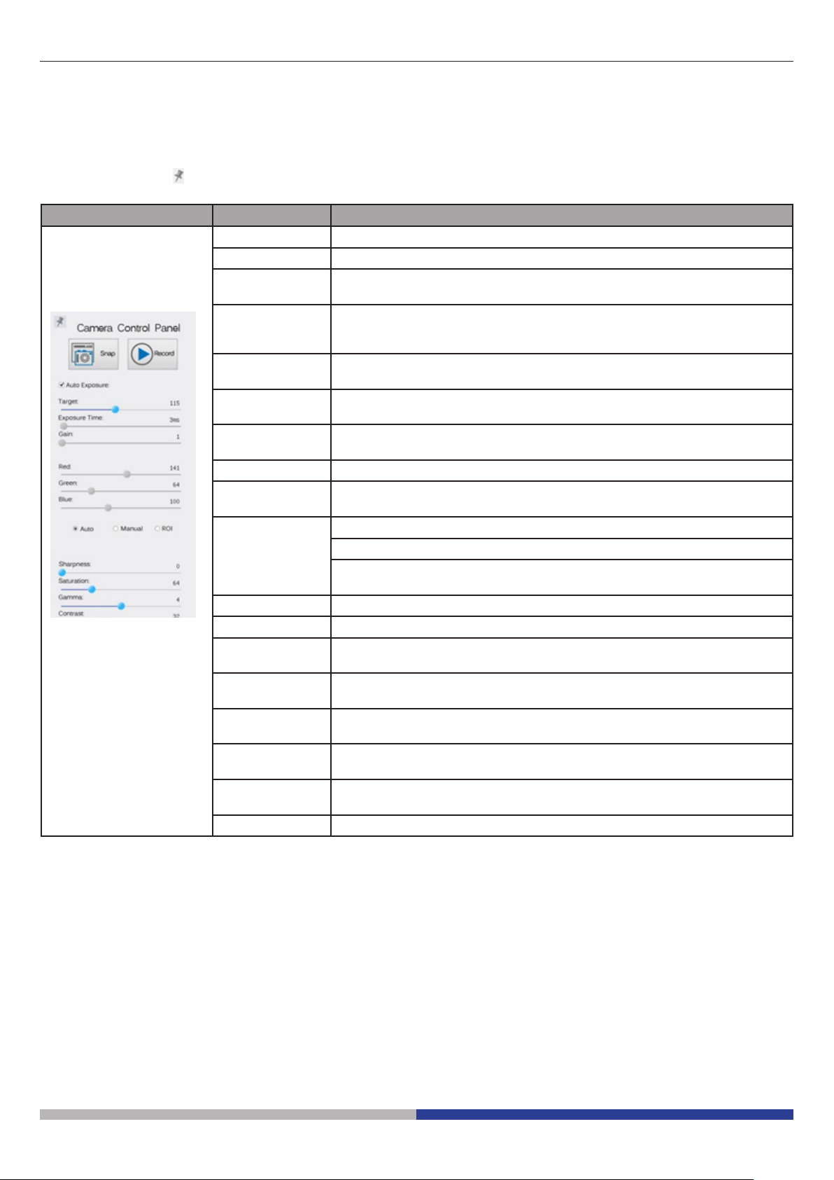
6.1 The Camera Control Panel
The Camera Control Panel controls the camera to achieve the best image quality according to the specic
applications. It will pop up automatically when mouse cursor is moved to the left side of the video window (in
measurement status, the Camera Control Panel will not pop up. Only when measurement process is terminated
will the Camera Control Panel pop up by moving mouse cursor to the left side of the video window).
Left-clicking button to achieve Display/ Auto Hide switch of the Camera Control Panel.
Control Panel Function Description
Snap Capture image from the current video window
Record Record video from the current video window
Auto Exposure When Auto Exposure is checked, the system will automatically adjust ex-
posure time according to the value of exposure compensation
Target Available when Auto Exposure is checked. Slide to left or right to adjust
Target according to the current video brightness to achieve proper bright-
ness value
Exposure Time Available when Auto Exposure is unchecked. Slide to left or right to redu-
ce or increase exposure time, adjusting brightness of the video
Gain Adjust Gain to reduce or increase brightness of video. The Noise will be
reduced or increased accordingly
Red Slide to left or right to decrease or increase the proportion of Red in RGB
on video
Green Green is base for reference and cannot be adjusted
Blue Slide to left or right to decrease or increase the proportion of Blue in RGB
on the video
White Balance Auto: White Balance adjustment according to the window video
Manual: Slide the Red or Blue to manually set the video White Balance
ROI: Set the White Balance according to the ROI. The ROI can be resized
and moved
Sharpness Adjust Sharpness level of the video window
Saturation Adjust Saturation level of the video window
Gamma Adjust Gamma level of the video. Slide to the right side to increase gam-
ma and to the left to decrease gamma
Contrast Adjust Contrast level of the video. Slide to the right side to increase con-
trast and to the left to decrease contrast
DC For DC illumination, there will be no uctuation in light source so no need
for compensating light ickering
AC(50HZ) Check AC(50HZ) to eliminate ickering “strap” caused by 50Hz illumina-
tion
AC(60HZ) Check AC(60HZ) to eliminate ickering “strap” caused by 60Hz illumina-
tion
Default Set all the settings in the Camera Control Panel to default values