Optimate TM270 User manual

Automatic charger for 12.8V &16V LiFePO4batteries • Chargeur
automatique pour batteries 12.8V/16V LiFePO4• Cargador automático
para baterías 12.8V &16V LiFePO4• Carregador automático para baterias
de 12.8V &16V LiFePO4• Automatische Ladegerät für 12.8V &16V LiFePO4
Batterien • Automatische lader voor 12.8V &16V LiFePO4accu’s
• Caricabatterie automatico per batterie 12.8V &16V LiFePO4
• Automatisk diagnostisk laddare för 12.8V &16V LiFePO4-batterier
MODEL: TM270 / TM271
TM272 / TM278
AC: 100 – 240VAC 50-60Hz
0.66A @ 240VAC 1.59A @ 100VAC
DC: 120W 12.8V 9.5A /
16V 7.5A
Thermally adjusted
INSTRUCTIONS FOR USE
IMPORTANT: Read completely
before charging
MODE D’EMPLOI
IMPORTANT: à lire avant
d’utiliser l’appareil
MODO DE EMPLEO
IMPORTANTE: a leer antes de
utilizar el aparato
ANWENDUNGSVORSCHRIFTEN
WICHTIG: Vollständig vor der
Benutzung lesen
GEBRUIKSAANWIJZING
BELANGRIJK: Lees volledig voor
gebruik
INSTRUÇÕES DE UTILIZAÇÃO
IMPORTANTE: Ler antes de
utilizar.
ISTRUZIONI PER L’USO
IMPORTANTE: da leggere prima
di utilizzare l’apparecchio
INSTRUKTIONER
VIKTIGT: läs följande fullständiga
instruktioner för användningen
innan du använder laddaren
12.8V (4 cells) & 16V (5 cells)
LiFePO4Lithium Iron Phospahte
batteries 2.5 - 200Ah
+ -

LEDs / SELECT
TEST LEDs
9.5A
7.5A
5
4
3
1a 1b 2 8
6
7
876
90 100%603010%
13.3V 13.6V+
13.13V13.00V12.80VV
8776
0
10V

3
IMPORTANT SAFETY
INSTRUCTIONS FOR CANADA & USA
THIS PORTION OF THE MANUAL CONTAINS IMPORTANT SAFETY INSTRUCTIONS FOR THE OptiMate
LITHIUM BATTERY CHARGER. IT IS OF THE UTMOST IMPORTANCE THAT EACH TIME, BEFORE
USING THE CHARGER, YOU READ AND EXACTLY FOLLOW THESE INSTRUCTIONS. SAVE THESE
INSTRUCTIONS.
AUTOMATIC CHARGER ONLY FOR 12.8V & 16V LIFEPO4(LITHIUM IRON PHOSPHATE ) BATTERIES.
A rechargeable LIFEPO4battery should comply with IEC62133*.
DO NOT USE FOR NiCd, NiMH, Lead-Acid or any other type of Li-Ion or
NON-RECHARGEABLE BATTERIES.
*IEC62133 - Safety requirements for portable sealed secondary cells containing alkaline or other
non acid electrolytes and for batteries made from them, for use in portable applications.
1. CAUTION : CLASS II APPLIANCE. DO NOT CONNECT TO GROUND.
2. For indoor use only. Do not expose charger to rain or snow.
3. Use of an attachment not recommended or sold by the battery charger manufacturer may result in a risk of fire, electric shock,or injury to persons.
4. To reduce risk of damage to electric plug and cord,pull by plug rather than cord when disconnecting charger.
5. An extension cord should not be used unless absolutely necessary. Use of improper extension cord could result in a risk of fire and electric shock.If
extension cord must be used make sure that :
a) pins on plug of extension cord are the same number, size and shape as those of plug on charger.
b) the extension cord is property wired and in good electrical condition,and
c) the conductor wire size is large enough for the AC ampere rating of the charger as specified in the table below.
AC INPUT RATING IN AMPERES
Equal to or greater than But less than
LENGTH OF CORD, FEET
(m)
AWG SIZE OF
CORD
2A 3A 25 (17.6)
50 (15.2)
100 (30.5)
18
18
14
6. Do not operate charger with damaged cord or plug - replace the cord or plug immediately.
7. Do not operate charger if it has received a sharp blow, been dropped,or otherwise damaged in any way; take it to a qualified serviceman.
8. Do not disassemble charger; take it to a qualified serviceman when service or repair is required.
Incorrect reassembly may result in a risk of electric shock or fire.
9. To reduce risk of electric shock, unplug the charger from outlet before attempting any maintenance or cleaning.
Turning off controls will not reduce this risk.Clean only with slightly moist,not wet, cloth.Do not use solvents.
10. WARNING - RISK OF EXPLOSIVE GASES.
a) WORKING IN VICINITY OF A LEAD-ACID BATTERY IS DANGEROUS. B ATTERIES GENERATE EXPLOSIVE GASES DURING NORMAL BATTERY OPERATION. FOR
THIS REASON, IT IS OF UTMOST IMPORTANCE THAT YOU FOLLOW THE INSTRUCTIONS EACH TIME YOU USE THE CHARGER.
b) To reduce risk of battery explosion,follow these instructions and those published by the battery manufacturer and manufacturer of any equipment you
intend to use in vicinity of the battery. Review cautionary marking on these products and on engine.
11. PERSONAL PRECAUTIONS.
a) Someone should be within range of your voice OR close enough to come to your aid when you work near a battery.
b) Have plenty of fresh water and soap nearby in case battery acid contacts skin, clothing or eyes.
c) Wear complete eye protection and clothing protection. Avoid touching eyes while working near a battery.
d) If battery acid contacts or enters eye, flood eye with cold running water for at least 10 minutes and get medical attention immediately. If battery acid
contacts skin or clothing, wash immediately with soap & water. If acid enters an eye , immediately flood eye with running cold water for at least 10 minutes
& get medical attention immediately.
e) NEVER smoke or allow a spark or flame in vicinity of battery or engine.
f) Be extra cautious to reduce risk of dropping a metal tool onto battery. It might spark or short-circuit battery or other electrical part that may cause
explosion.
g) Remove personal metal items such as rings, bracelets ,necklaces , and watches when working with a battery. A battery can produce a short-circuit
current high enough to weld a ring or the like to metal, causing a severe burn.
i) NEVER charge a frozen battery.
12. PREPARING TO CHARGE
a) If necessary to remove battery from vehicle to charge,always remove grounded terminal from battery first.
Make sure all accessories in the vehicle are off, so as not to cause an arc.
b) Be sure area around battery is well ventilated while battery is being charged. Gas can be forcefully blown
away by using a piece of cardboard or other non-metallic material as a fan.
SAFETY US & CAN

4
c) Clean battery terminals.Be careful to keep corrosion from coming in contact with eyes.
d) Study all battery manufacturer’s specific precautions such as removing or not removing cell caps while charging and recommended rates of charge.
e) Determine voltage of battery by referring to vehicle or other user’s manual and BEFORE MAKING THE BATTERY CONNECTIONS, MAKE SURE THAT THE
VOLTAGE OF THE BATTERY YOU ARE GOING TO CHARGE MATCHES THE OUTPUT VOLTAGE OF THE CHARGER.
13. CHARGER LOCATION.
a) Locate charger as far away from battery as DC cables permit.
b) Never place charger directly above batterv being charged; gases from battery will corrode and damage the charger. c) Never allow battery acid to drip on charger
when reading gravity or filling battery. Do not operate charger in a closed-in area or restrict ventilation in any way.
d) Do not set a battery on top of charger. IMPORTANT : Place charger on a hard flat surface or mount onto a vertical surface. Do not place on plastic, leather
or textile surface.
14. DC CONNECTION PRECAUTIONS
a) Connect and disconnect DC output clips only after setting any charger switches to off position and removing
AC cord from electric outlet. Never allow clips to touch each other, however should this happen no damage will result to the charger circuit & the
automatic charging programme will just reset to «start».
b) Attach clips to battery and chassis as indicated in 15(e), 15(f), and 16(b) through 16(d).
NOTE : This battery charger has an automatic safety feature that will prevent it from operating if the battery has
been inversely connected. Set charger switches to off position and/or remove AC cord from electrical outlet, disconnect the battery clips, then
reconnect correctly according to the instructions below.
15. FOLLOW THESE STEPS WHEN BATTERY IS INSTALLED IN VEHICLE. A SPARK NEAR A
BATTERY MAY CAUSE BATTERY EXPLOSION. TO REDUCE RISK OF A SPARK NEAR BATTERY :
a) Position AC and DC cords so as to reduce risk of damage by hood, door or moving engine part.
b) Stay clear of fan -blades, belts,pulleys,and other parts that can cause injury to persons.
c) Check polarity of battery posts.POSITIVE (POS, P, +) battery post usually has larger diameter than NEGATIVE (NEG, N,–) post.
d) Determine which post of battery is grounded (connected) to the chassis. If negative post is grounded to chassis (as in most vehicles),see (e). If positive
post is grounded to the chassis,see (f).
e) For negative-grounded vehicle, connect POSITIVE (RED) clip from battery charger to POSITIVE (POS, P, + ) ungrounded post of battery. Connect NEGATIVE
(BLACK) clip to vehicle chassis or engine block away from battery. Do not connect clip to carburetor, fuel lines, or sheet-metal body parts. Connect to a
heavy gage metal part of the frame or engine block.
f) For positive-grounded vehicle, connect NEGATIVE (BLACK) clip from battery charger to NEGATIVE (NEG. N , -) ungrounded post of battery. Connect
POSITIVE (RED) clip to vehicle chassis or engine block away from battery. Do not connect clip to carburetor, fuel lines, or sheet-metal body parts. Connect
to a heavy gage metal part of the frame or engine block.
g) When disconnecting charger, turn switches to off, disconnect AC cord,remove clip from vehicle chassis,and then remove clip from battery terminal.
h) See operating instructions for length of charge information.
16. FOLLOW THESE STEPS WHEN BATTERY IS OUTSIDE VEHICLE. A SPARK NEAR THE BATTERY
MAY CAUSE BATTERY EXPLOSION. TO REDUCE RISK OF A SPARK NEAR BATTERY :
a) Check polarity of battery posts. POSITIVE (POS, P, +) battery post usually has a larger diameter than NEGATIVE (NEG,N, -) post.
b) This battery charger has an automatic safety feature that will prevent it from operating if the battery has been
inversely connected. The charger does allow charge current unless a voltage of at least 0.5V is sensed.
c) Connect POSITIVE (RED) charger clip to POSITIVE (POS, P, +) post of battery.
d) Connect NEGATIVE (BLACK) charger clip to NEGATIVE (NEG, N, -) battery post of the battery.
e) Do not face battery when making final connection.
f) When disconnecting charger, always do so in reverse sequence of connecting procedure & break first connection while as far away from battery as
practical.
g) A marine (boat) battery must be removed & charged on shore. To charge it on board requires equipment specially designed for marine use.
SAFETY US & CAN

5
AUTOMATIC DIAGNOSTIC CHARGER FOR 12.8V & 16V LiFePO4(LITHIUM IRON
PHOSPHATE ) BATTERIES UP TO 200AH:
SAFETY WARNING AND NOTES: IF YOU HAVE NOT YET DONE SO, READ THE
PRECEDING PAGES LABELLED "IMPORTANT SAFETY INSTRUCTIONS" BEFORE
OPERATING THIS CHARGER.
This appliance can be used by children aged from 8 years and above and persons with reduced
physical,sensory or mental capabilities or lack of experience and knowledge if they have been given
supervision or instruction concerning use of the appliance in a safe way and understand the hazards
involved. Children shall not play with the appliance. Cleaning and user maintenance shall not be made
by children without supervision.
CORRECT USE:
Use the charger only if the input and output leads and connectors are in good, undamaged condition. If the input
cable is damaged, it is essential to have it replaced without delay by the manufacturer, his authorised service
agent or a qualified workshop, to avoid danger. Protect your charger from damp and humid conditions both during use and
in storage. Damage resulting from corrosion, oxidation or internal electrical short-circuiting is not covered by warranty. Distance the
charger from the battery during charging to avoid contamination by or exposure to acid or acidic vapours. If using it in the horizontal
orientation, place the charger on a hard, flat surface, but NOT on plastic, textile or leather. Use the fixing holes provided in the
enclosure base to attach the charger to any convenient, sound vertical surface.
EXPOSURE TO LIQUIDS: This charger is designed to withstand exposure to liquids accidentally spilled or splashed onto the
casing from above, or to light rainfall. Prolonged exposure to falling rain is inadvisable and longer service life will be obtained by
minimizing such exposure.Failure of the charger due to oxidation resulting from the eventual penetration of liquid into the electronic
components, connectors or plugs,is not covered by warranty.
VERY FLAT NEGLECTED BATTERIES: Pay particularly close attention to the following A LiFePO4 battery
left deep-discharged for an extended period may develop permanent damage in one or more cells.
Such batteries may heat up excessively during charging. During the SAVE mode the program limits charge current
if the voltage is below nomimal (12.8V / 16V) and the program should detect obvious cell damage and will automatically suspend
charging, but the higher the cell count in parallel the more difficult it is to detect a bad cell e.g. a 5Ah battery typically has 4 series
connected sets of 2 parallel cells (4S2P configuration - total 8 cells), a 10Ah battery has 4 series connected sets of 4 parallel cells
(4S4P configuration - total 16 cells).
ALWAYS monitor the battery temperature during the first hour, then hourly there-after. If at any
time the battery is uncomfortably hot to touch or you notice any unusual signs, DISCONNECT THE
CHARGER IMMEDIATELY.
CONNECTING THE CHARGER TO THE BATTERY
1. Disconnect AC power supply before making or breaking DC / battery connections.
2. If charging a battery in the vehicle with the battery clips, before making connections, first check that the battery clips can be
safely and securely positioned clear from surrounding wiring, metal tubing or the chassis. Make connections in the following
order: First connect to the battery terminal not connected to the chassis (normally positive), then
connect the other battery clip (normally negative) to the chassis well away from the battery and
fuel line. Always disconnect in reverse sequence.
3. When charging a battery out of the vehicle with the battery clips, place it in a well ventilated area. Connect the charger to the
battery: RED clamp to POSITIVE (POS, P or +) terminal and BLACK clamp to NEGATIVE (NEG, N or –) terminal. Make sure the
connections are firm and secure. Good contact is important.
PROCEEDING TO CHARGE
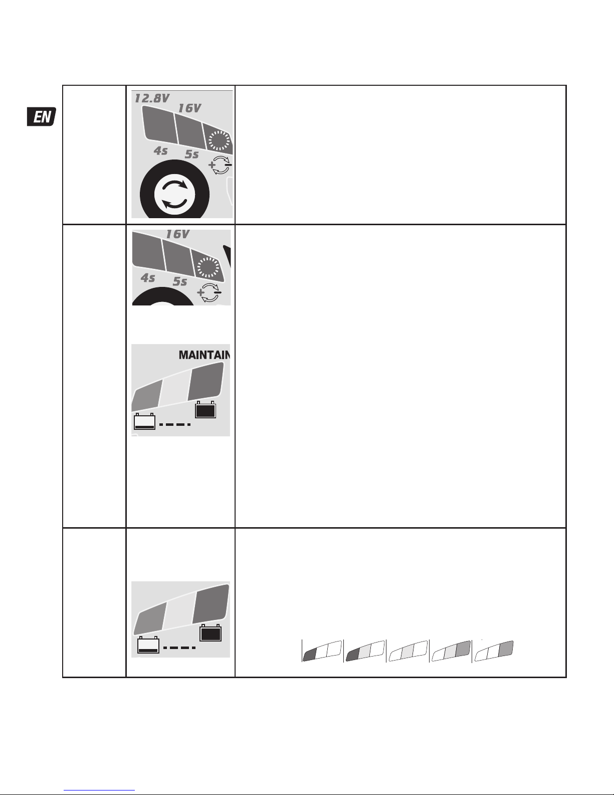
CHARGING TIME
Charge time will be affected by ambient temperature. The safeTº program limits charge current if the temperature measured at the
OptiMate Lithium is below 0ºC / 32ºF or above 45ºC / 113ºF. Within the normal temperature range the ampmatic™ LiFePO4specific
program automatically determines the most efficient rate of charge current for the connected battery, according to its state of charge,
state of health, and electrical storage (Ah) capacity. The delivered current may be anywhere from 1.25A to 9.5A.
Charge time on a flat but otherwise undamaged battery:
For batteries rated from 2.5Ah to 10Ah: 60 to 120 minutes to progress to the voltage retention test.
For batteries rated above 10Ah: approximately 10% of the battery’s Ah rating, so a 50Ah battery should take no more than about
5 hours to progress to the voltage retention test.
Deep discharged batteries may take longer.
SAFETY

6
CHARGE PROGRAM
If voltage selection in STEP 1 matches the expected battery voltage and there are no connection errors as described in
STEP 2, then fully automatic operation starts from STEP 3.
STEP 1
Voltage
Selection
S
e
l
e
c
t
T
O
U
C
H
TEST
°t
9A
7A
5
4
3
1a 1b 2
8
6
7
LED #1a / 1b: Confirms AC power supply to the charger and selected battery
voltage.
Changing voltage selection: Disconnect charger from battery. Place and hold finger on
Select-TOUCH sensor. The selected voltage LED brightens to confirm touch. (i.e. if ‘12.8V’
was on, then ‘12.8V’ will brighten).
After 3 seconds the voltage selection changes, then SAVE (#3), CHARGE (#4) and TEST
(#6,7, 8) LEDs flash twice to confirm selection is in memory.
LED #1a => 12.8V
LED #1b => 16V
NOTE: Selection remains even if AC power is lost.
STEP 2
Protection
Low Volt
16V
battery
BMS reset
24V
2.5A
5A
12V
24V
12V
S
e
l
e
c
t
°t
TEST
2
1a
876
5
4
3
1b
S
e
l
e
c
t
T
O
U
C
H
TEST
°t
9A
7A
5
4
3
1a 1b 2
8
6
7
Charger will not proceed without user interaction.
LED #2 REVERSE POLARITY: Lights when the battery connections are incorrect.
The charger is electronically protected so no damage will result, and the output will
remain disabled until the connections are corrected.
VOLTAGE SAFETY CHECK:
12.8V (#1a) and 16V LEDs (#1b) alternate and green test LED (#6)
lights.
12.8V is selected and a battery with voltage exceeding 14.8V is connected.
Connected battery may be 16V.
Action: Disconnect battery, select 16V.
16V (#1b) and 12.8V (#1a) alternate and red test LED (#8) lights.
16V (#1b) selected and a battery with voltage below 14.8V is connected:
The connected battery may be 12.8V or it may be a deep discharged 16V battery.
Action: Physically check battery. If nominal voltage is 12.8V, disconnect battery and select
12.8V.
If nominal voltage is 16V, hold finger on Select-TOUCH. After 5 seconds program will
proceed to STEP 3.
BMS RESET: for batteries with a battery management system (BMS) that protects
against deep discharge. IMPORTANT! Before proceeding, confirm the nominal
battery voltage matches the selected charge voltage.
Disconnect the charger from mains supply. Wait for LED #1a/1b to go out. Reconnect to
mains supply. A special BMS reset pulse is delivered for up to 5 seconds. The program
should continue to STEP 4.
STEP 3
TEST
before
charge
TEST LEDs
6 : GREEN
7 : YELLOW
8 : RED
24V
2.5A
5A
12V
24V
12V
S
e
l
e
c
t
°t
TEST
2
1a
876
5
4
3
1b
TEST LEDs #6/7/8 indicate the battery condition prior to charging. Consult the table on
page 2 to match TEST LED indication to an estimated state of charge percentage (SOC%).
During the test:
OPTIMIZE minimum charge time is set according to the test result, varying between 10
minutes for a battery with 80% or higher state of charge to 120 minutes
for a battery with 40% or less state of charge.
Ambient temperature is measured to determine charge voltage parameters.
Charging commences after 10 seconds.
876
90 100%603010%
13.3V 13.6V+
13.13V13.00V12.80VV
8776
0
10V

7
STEP 4
SAVE
LED #3 : RED
24V
2.5A
5A
12V
24V
12V
S
e
l
e
c
t
°t
TEST
2
1a
876
5
4
3
1b
IMPORTANT: If this mode engages read the section VERY FLAT NEGLECTED
BATTERIES on the preceding page.
NOTE: 16V voltage values in brackets.
This mode engages if the battery was more than 90% discharged / voltage is below
12.8V (16V). safeTº: Charge current is automatically adjusted according to voltage
and ambient temperature measured during the test.
VERY LOW VOLTAGE SAVE for batteries between 0.6V (0.75V) and 8.8V (11V):
Current starts at 125mA and will increase to 325mA depending on charge progress. If
the voltage did not rise above 8.8V (11V) within 2 hours, charging will be suspended
and the TEST LED #8 (red) will flash, indicating the battery may have suffered
permanent damage or a professional assessment is required.
LOW VOLTAGE SAVE for batteries between 8.9V (11.1V) and 12.8V (16V): Maximum
current is set to 1.25A. The battery's charge acceptance is monitored for unusual
behaviour. A healthy LiFePO4battery will progress to CHARGE mode within 4 hours,
otherwise charging will be suspended and TEST LED #8 (red) will flash, indicating the
battery may have suffered permanent damage or a professional assessment is
required.
STEP 5
CHARGE
LED #4 : YELLOW
24V
2.5A
5A
12V
24V
12V
S
e
l
e
c
t
°t
TEST
2
1a
876
4
1b
The safeTº program limits charge current if the temperature measured at the
OptiMate Lithium is below 0ºC / 32ºF or above 45ºC / 113ºF. If the temperature was
initially below 0ºC / 32ºF charge current is limited to 325mA only for the first hour after
which the battery is expected to have increased it's internal temperature within the
normal temperature zone.
Within the normal temperature zone the ampmatic™ LiFePO4specific program
automatically determines the most efficient rate of charge current for the connected
battery, according to its state of charge, state of health, and electrical storage (Ah)
capacity. The delivered current may be anywhere from 1.25A to 9.5A (7.5A for 16V
batteries).
For batteries with an electrical storage (Ah) capacity less than 10Ah (8Ah) charge
current is automatically adjusted lower to an average equal to battery Ah capacity, e.g.
a 2.5Ah / 2500mAh battery receive an average of 2.5 Amps.
NOTE: For safety reasons there is an overall charge time limit of 24 hours for SAVE and
CHARGE modes.
STEP 6
OPTIMIZE
LED #5 : YELLOW
DC POWER SUPPLY
Select-TOUCH
for 5 seconds when
battery is connected.
S
e
l
e
c
t
°t
1a
876
5
1b 2
The OPTIMIZE mode starts when the voltage has reached 14.4V (18V) for the first time
during bulk CHARGE mode.
The ampmatic™ current control program now delivers pulses of current to equalise
the individual cells within the battery and optimizes charge level.
Charging should complete within the minimum charge time set during STEP 3, but if
the battery requires further charging the program will extend OPTIMIZE mode up to a
maximum of 2 hours.
STEP 7
TEST after
charge
LED #6 FLASHING
24V
2.5A
5A
12V
24V
12V
S
e
l
e
c
t
°t
TEST
2
1a
6
5
1b
TEST after charge : Delivery of current to the battery is interrupted for
30 minutes* to allow the program to determine the battery’s ability
to retain charge.
*IF charging started in SAVE mode (LED #3, indicating a deep discharged battery) or
the the voltage retention test is extended to 12 hours to confirm battery health.
The TEST result (indicated on LED # 6, 7, 8) is adjusted in real time according to the
measured battery voltage. Consult the “EARLY WARNING OF BATTERY PROBLEMS” table
on page 2 to match TEST LED indication to an estimated state of charge percentage
(SOC%).
More information is provided in the section “NOTES ON TEST RESULTS”.
STEP 8
OptiMATE
smart
MAINTAIN
LED #6 / 7 / 8 ON
24V
2.5A
5A
12V
24V
12V
S
e
l
e
c
t
°t
TEST
2
1a
876
5
1b
For batteries with a good
state of health LED #6
(green) will remain on.
MAINTENANCE CHARGE: LED #6 / 7 / 8 steady on
according to final voltage measured at termination of STEP 7.
The MAINTENANCE CHARGE CYCLE consists of 30 minute charge periods followed by
and alternating with a 30 minute ‘rest’ periods, during which there is no charge current.
During the 30 minute charge cycles current is delivered only if the battery has lost
charge.
The BATTERY REFRESH CYCLE is performed if the charger detects the battery has lost
significant charge. The program returns to OPTIMIZE mode (LED #5) and then proceeds
to the voltage retention test and maintenance charge cycle.
Read section MAINTAINING A LITHIUM BATTERY FOR EXTENDED PERIODS.
NOTES ON TEST RESULTS:

8
1. For any test result other than green #6, disconnect the battery from the electrical system it supports, and reconnect the OptiMate. If a
better test result is now obtained, this suggests that the power losses are partly due to an electrical problem in the electrical system and
not in the battery itself.
2. If the red LED #8 alone, or the yellow #7 and red LED #8 indicate together (or yellow LED alone for a sealed battery), a significant
problem exists. The red / yellow+red LEDs mean that after being charged the battery’s voltage is not being sustained or that despite
recovery attempts the battery was irrecoverable. This may be due to a defect in the battery itself, such as a short-circuited cell, or, in
the case of a battery still connected to the electrical system it supports, it may be signalling a loss of current through deteriorated wiring
or a degraded switch or contact, or in-circuit current-consuming accessories.
A sudden load being switched on while the charger is connected can also cause the battery voltage to dip significantly.
3. TEST LED #8 (red) flashing - Charging is suspended. During the voltage retention test the voltage reduced below 12.8V within the first
30 minutes, indicating the battery may have suffered permanent damage and a professional assessment is required. More information
on OptiMate TEST or MONITOR products can be found at www.optimate1.com.
MAINTAINING A LITHIUM BATTERY FOR EXTENDED PERIODS: A LiFePO4battery can be left connected to the OptiMate
Lithium for any extended period of time. The OptiMate Lithium maintenance program is fully automatic, it continuously monitors the
battery voltage and delivers current only if it sensed the battery has lost charge (possibly through connected vehicle or other circuitry
or self discharge). The OptiMate Lithium's maintenance program guarantees the battery will remain at or close to full charge, but
never overcharged.
ECO POWER SAVING MODE WHEN THE CHARGER IS CONNECTED TO AC SUPPLY:
The power converter switches to ECO mode when the charger is not connected to a battery resulting in a very low power draw of less
than 0.5W, equivalent to power consumption of 0.012 kWh per day. When a battery is connected to the charger power consumption
depends on the current demand of the battery and its connected vehicle / electronic circuitry. After the battery has been charged and
the charger is in long term maintenance charge mode (to keep the battery at 100% charge) the total power consumption is estimated to
be 0.024kWh or less per day.
LIMITED WARRANTY
TecMate (International) SA, B-3300 Tienen, Belgium, offers this limited warranty to the original purchaser at retail of this
product. This limited warranty is not transferable. TecMate (International) warrants this battery charger for three years from
date of purchase at retail against defective material or workmanship. If such should occur the unit will be repaired or replaced
at the option of the manufacturer. It is the obligation of the purchaser to forward the unit together with proof of purchase (see
NOTE), transportation or mailing costs prepaid, to the manufacturer or its authorized representative. This limited warranty is
void if the product is misused, subjected to careless handling, or repaired by anyone other than the factory or its authorized
representative. The manufacturer makes no warranty other than this limited warranty and expressly excludes any implied
warranty including any warranty for consequential damages.
THIS IS THE ONLY EXPRESS LIMITED WARRANTY AND THE MANUFACTURER NEITHER ASSUMES NOR AUTHORIZES ANYONE TO
ASSUME OR MAKE ANY OTHER OBLIGATION TOWARDS THE PRODUCT OTHER THAN THIS EXPRESS LIMITED WARRANTY. YOUR
STATUTORY RIGHTS ARE NOT AFFECTED.
NOTE: Details at www.tecmate.com/warranty.
copyright © 2015 TecMate International
Optimate 7 and the names of other battery care products mentioned in these instructions such as BatteryMate, TestMateand
TestMate mini, are registered trademarks of TecMate International NV.
WARRANTY in Canada, USA, Central America and South America:
TecMate North America, Oakville, ON, Canada, as a wholy owned subsidiary of TecMate International, assumes the
responsibility for product warranty in these regions.
More information on TecMate products can be found at www.tecmate.com.

9
INSTRUCTIONS IMPORTANTES CONCERNANT LA SÉCURITÉ
CONSERVER CES INSTRUCTIONS. CE MANUEL CONTIENT DES INSTRUCTIONS
IMPORTANTES CONCERNANT LA SÉCURITÉ ET LE FONCTIONNEMENT DU
CHARGEUR OPTIMATE 7 12.8V & 16V LIFEPO4.
CHARGEUR AUTOMATIQUE POUR BATTERIES 12.8V & 16V LIFEPO4
NE CONVIENT PAS POUR LES BATTERIES NiCd, NiMH, Plomb-Acide OU NON
RECHARGEABLES.
AVERTISSEMENT :
N’utiliser l’appareil qu’à l’intérieur. Ne pas exposer à la pluie ou à la neige. Appareil de Classe II.
a) CONSERVER CES INSTRUCTIONS. CE MANUEL CONTIENT DES INSTRUCTIONS IMPORTANTES CONCERNANT LA SÉCURITÉ
ET LE FONCTIONNEMENT.
b) IL EST DANGEREUX DE TRAVAILLER A PROXIMITÉ D’UNE BATTERIE AU PLOMB. LES BATTERIES PRODUISENT DES GAZ
EXPLOSIFS EN SERVICE NORMAL. IL EST AUSSI IMPORTANT DE TOUJOURS RELIRE LES INSTRUCTIONS AVANT D’UTILISER
LE CHARGEUR ET DE LES SUIVRE À LA LETTRE.
c) POUR RÉDUIRE LE RISQUE D’EXPLOSION, LIRE CES INSTRUCTIONS ET CELLES QUI FIGURENT SUR LA BATTERIE.
d) NE JAMAIS FUMER PRÈS DE LA BATTERIE OU DU MOTEUR ET ÉVITER TOUTE ÉTINCELLE OU FLAMME NUE À PROXIMITÉ DE
CES DERNIERS.
e) UTILISER LE CHARGEUR POUR CHARGER UNE BATTERIE AU PLOMB UNIQUEMENT. CE CHARGEUR N’EST PAS CONÇU POUR
ALIMENTER UN RÉSEAU ÉLECTRIQUE TRÈS BASSE TENSION NI POUR CHARGER DES PILES SÈCHES. LE FAIT D’UTILISER LE
CHARGEUR POUR CHARGER DES PILES SÈCHES POURRAIT ENTRAÎNER L’ÉCLATEMENT DES PILES ET CAUSER DES
BLESSURES OU DES DOMMAGES.
f) NE JAMAIS CHARGER UNE BATTERIE GELÉE.
g) S’IL EST NÉCESSAIRE DE RETIRER LA BATTERIE DU VÉHICULE POUR LA CHARGER, TOUJOURS DÉBRANCHER LA BORNE DE
MISE À LA MASSE EN PREMIER. S’ASSURER QUE LE COURANT AUX ACCESSOIRES DU VÉHICULE EST COUPÉ AFIN D’ÉVITER
LA FORMATION D’UN ARC.
h) PRENDRE CONNAISSANCE DES MESURES DE PRÉCAUTION SPÉCIFIÉES PAR LE FABRICANT DE LA BATTERIE, P. EX.,
VÉRIFIER S‘IL FAUT ENLEVER LES BOUCHONS DES CELLULES LORS DU CHARGEMENT DE LA BATTERIE, ET LES TAUX DE
CHARGEMENT RECOMMANDÉS.
i) SI LE CHARGEUR COMPORTE UN SÉLECTEUR DE TENSION DE SORTIE, CONSULTER LE MANUEL DE L’USAGER DE LA
VOITURE POUR DÉTERMINER LA TENSION DE LA BATTERIE ET POUR S’ASSURER QUE LA TENSION DE SORTIE EST
APPROPRIÉE. SI LE CHARGEUR N’EST PAS MUNI D’UN SÉLECTEUR, NE PAS UTILISER LE CHARGEUR À MOINS QUE LA
TENSION DE LA BATTERIE NE SOIT IDENTIQUE À LA TENSION DE SORTIE NOMINALE DU CHARGEUR.
j) NE JAMAIS PLACER LE CHARGEUR DIRECTEMENT SOUS LA BATTERIE À CHARGER OU AU-DESSUS DE CETTE DERNIÈRE.
LES GAZ OU LES FLUIDES QUI S’ÉCHAPPENT DE LA BATTERIE PEUVENT ENTRAÎNER LA CORROSION DU CHARGEUR OU
L’ENDOMMAGER. PLACER LE CHARGEUR AUSSI LOIN DE LA BATTERIE QUE LES CABLES C.C. LE PERMETTENT.
k) NE PAS FAIRE FONCTIONNER LE CHARGEUR DANS UN ESPACE CLOS ET/OU NE PAS GÊNER LA VENTILATION.
l) METTRE LES INTERRUPTEURS DU CHARGEUR HORS CIRCUIT ET RETIRER LE CORDON C.A. DE LA PRISE AVANT DE METTRE
ET D’ENLEVER LES PINCES DU CORDON C.C. S’ASSURER QUE LES PINCES NE SE TOUCHENT PAS.
m) SUIVRE LES ÉTAPES SUIVANTES LORSQUE LA BATTERIE SE TROUVE DANS LE VÉHICULE.
UNE ÉTINCELLE PRÈS DE LA BATTERIE POURRAIT PROVOQUER L’EXPLOSION DE CETTE DERNIÈRE. POUR RÉDUIRE LE
RISQUE D’ÉTINCELLE À PROXIMITÉ DE LA BATTERIE :
(i) PLACER LES CORDONS C.A. ET C.C. DE MANIÈRE À ÉVITER QU’ILS SOIENT ENDOMMAGÉS PAR LE CAPOT, UNE PORTIÈRE
OU LES PIÈCES EN MOUVEMENT DU MOTEUR ;
(ii) FAIRE ATTENTION AUX PALES, AUX COURROIES ET AUX POULIES DU VENTILATEUR AINSI QU’À TOUTE AUTRE PIÈCE
SUSCEPTIBLE DE CAUSER DES BLESSURES ;
(iii) VÉRIFIER LA POLARITÉ DES BORNES DE LA BATTERIE. LE DIAMÈTRE DE LA BORNE POSITIVE
(POS, P, +) EST GÉNÉRALEMENT SUPÉRIEUR À CELUI DE LA BORNE NÉGATIVE (NÉG, N, –) ;
(iv) DÉTERMINER QUELLE BORNE EST MISE À LA MASSE (RACCORDÉE AU CHÂSSIS). SI LA BORNE
SÉCURITÉ US & CAN

10
NÉGATIVE EST RACCORDÉE AU CHÂSSIS (COMME DANS LA PLUPART DES CAS), VOIR LE POINT (v).
SI LA BORNE POSITIVE EST RACCORDÉE AU CHÂSSIS, VOIR LE POINT (vi) ;
(v) SI LA BORNE NÉGATIVE EST MISE À LA MASSE, RACCORDER LA PINCE POSITIVE (ROUGE) DU
CHARGEUR À LA BORNE POSITIVE (POS, P, +) NON MISE À LA MASSE DE LA BATTERIE. RACCORDER LA
PINCE NÉGATIVE (NOIRE) AU CHÂSSIS DU VÉHICULE OU AU MOTEUR, LOIN DE LA BATTERIE. NE PAS
RACCORDER LA PINCE AU CARBURATEUR, AUX CANALISATIONS D’ESSENCE NI AUX PIÈCES DE LA
CARROSSERIE EN TÔLE. RACCORDER À UNE PIÈCE DU CADRE OU DU MOTEUR EN TÔLE DE FORTE
ÉPAISSEUR ;
(vi) SI LA BORNE POSITIVE EST MISE À LA MASSE, RACCORDER LA PINCE NÉGATIVE (NOIRE) DU
CHARGEUR À LA BORNE NÉGATIVE (NÉG, N, –) NON MISE À LA MASSE DE LA BATTERIE. RACCORDER
LA PINCE POSITIVE (ROUGE) AU CHÂSSIS DU VÉHICULE OU AU MOTEUR, LOIN DE LA BATTERIE. NE
PAS RACCORDER LA PINCE AU CARBURATEUR, AUX CANALISATIONS D’ESSENCE NI AUX PIÈCES DE LA
CARROSSERIE EN TÔLE. RACCORDER À UNE PIÈCE DU CADRE OU DU MOTEUR EN TÔLE DE FORTE
ÉPAISSEUR ;
(vii) BRANCHER LE CORDON D’ALIMENTATION C.A. DU CHARGEUR ;
(viii) POUR INTERROMPRE L’ALIMENTATION DU CHARGEUR, METTRE LES INTERRUPTEURS HORS
CIRCUIT, RETIRER LE CORDON C.A. DE LA PRISE, ENLEVER LA PINCE RACCORDÉE AU CHÂSSIS ET EN
DERNIER LIEU CELLE RACCORDÉE À LA BATTERIE.
n) SUIVRE LES ÉTAPES SUIVANTES LORSQUE LA BATTERIE EST À L’EXTÉRIEUR DU VÉHICULE.
UNE ÉTINCELLE PRÈS DE LA BATTERIE POURRAIT PROVOQUER L’EXPLOSION DE CETTE DERNIÈRE. POUR RÉDUIRE LE
RISQUE D’ÉTINCELLE À PROXIMITÉ DE LA BATTERIE :
(i) VÉRIFIER LA POLARITÉ DES BORNES DE LA BATTERIE. LE DIAMÈTRE DE LA BORNE POSITIVE
(POS, P, +) EST GÉNÉRALEMENT SUPÉRIEUR À CELUI DE LA BORNE NÉGATIVE (NÉG, N, –) ;
(ii) RACCORDER UN CÂBLE DE BATTERIE ISOLÉ No 6 AWG MESURANT AU MOINS 60 CM DE
LONGUEUR À LA BORNE NÉGATIVE (NÉG, N, –) ;
(iii) RACCORDER LA PINCE POSITIVE (ROUGE) À LA BORNE POSITIVE (POS, P, +) DE LA BATTERIE ;
(iv) SE PLACER ET TENIR L’EXTRÉMITÉ LIBRE DU CÂBLE AUSSI LOIN QUE POSSIBLE DE LA BATTERIE,
PUIS RACCORDER LA PINCE NÉGATIVE (NOIRE) DU CHARGEUR À L’EXTRÉMITÉ LIBRE DU CÂBLE ;
(v) NE PAS SE PLACER FACE À LA BATTERIE POUR EFFECTUER LE DERNIER RACCORDEMENT ;
(vi) RACCORDER LE CORDON D’ALIMENTATION C.A. DU CHARGEUR À LA PRISE ;
(vii) POUR INTERROMPRE L’ALIMENTATION DU CHARGEUR, METTRE LES INTERRUPTEURS HORS
CIRCUIT, RETIRER LE CORDON C.A. DE LA PRISE, ENLEVER LA PINCE RACCORDÉE AU CHÂSSIS ET EN
DERNIER LIEU CELLE RACCORDÉE À LA BATTERIE. SE PLACER AUSSI LOIN QUE POSSIBLE DE LA BATTERIE
POUR DÉFAIRE LA PREMIÈRE CONNEXION.
SÉCURITÉ US & CAN

11
CHARGEUR AUTOMATIQUE AVEC DIAGNOSTIC POUR BATTERIES 12.8 V & 16V
DE3Ah à200Ah :
IMPORTANT : LIRE ENTIÈREMENT LES INSTRUCTIONS SUIVANTES AVANT D’UTILISER LE CHARGEUR
Cet appareil n’est pas destiné à être utilisé par des personnes (y compris des enfants) possédant des
capacités physiques, sensorielles ou mentales réduites, ou manquant d'expérience et de connaissance,
sauf si elles bénéficient d’une surveillance ou ont reçu des instructions concernant l’utilisation de
l’appareil d’une personne responsable de leur sécurité. Les enfants doivent faire l’objet d’une surveillance
pour s’assurer qu’ils ne jouent pas avec l’appareil.
AVERTISSEMENT DE SÉCURITÉ et REMARQUES:Les batteries émettent des GAZ EXPLOSIFS - il faut interdire les
flammes ou les étincelles à proximité.
Avant d’établir ou de rompre les connexions de courant continu à la batterie, déconnecter l’alimentation secteur. L’acide des
batteries est un puissant corrosif. Porter des vêtements et lunettes protecteurs et éviter tout contact. En cas de contact accidentel,
laver immédiatement à l’eau et au savon. S’assurer que les bornes des batteries ne sont pas branlantes ; le cas échéant la batterie
doit subir une évaluation professionnelle. Si les bornes sont corrodées, nettoyer à l’aide d’une brosse de cuivre ; si elles sont
grasses ou sales, nettoyer à l’aide d’un torchon trempé dans du détergent. Utiliser uniquement le chargeur si les câbles et
connecteurs d’entrée et de sortie sont en bon état et non endommagés. Si le câble d’entrée est endommagé, il est essentiel de le
faire remplacer par le constructeur, son agent de service autorisé ou un atelier qualifié, pour éviter tout danger. Protéger le chargeur
contre les acides et fumées acides, l’humidité et un environnement humide, aussi bien durant l’usage que l’entreposage. Les dégâts
résultant de la corrosion, de l’oxydation ou de courts-circuits internes ne sont pas couverts par la garantie. Durant le chargement,
éloigner le chargeur de la batterie pour éviter la contamination par l’acide ou les vapeurs acides ou l’exposition à ceux-ci. En cas
d’utilisation horizontale, placer le chargeur sur une surface dure et plane, PAS en plastique, tissu ou cuir. Utiliser les trous de fixation
de la base pour fixer le chargeur sur toute surface verticale appropriée et solide.
EXPOSITION AUX LIQUIDES : Ce chargeur est conçu pour résister à l’exposition aux liquides qui tomberaient accidentellement
sur le boîtier, ou à une pluie légère. Une exposition prolongée à des liquides tombants ou à la pluie est à déconseiller. Une durée de
vie supérieure résultera d’une telle précaution. Une panne due à l’oxydation résultant d’une pénétration de liquide dans les
composants électroniques,bloc connecteurs ou fiches,ne sera pas couverte par la garantie.
BRANCHEMENT DU CHARGEUR A LA BATTERIE
1.
Débranchez l’alimentation secteur avant d’effectuer un branchement CC/batterie ou de le débrancher.
2. Si vous chargez une batterie installée dans le véhicule avec les pinces pour batterie, avant les branchements, vérifiez d’abord
que les pinces pour batterie peuvent être positionnées en toute sécurité loin du câblage voisin, d’un tube métallique ou du
châssis. Respectez l’ordre qui suit : branchez d’abord la borne de la batterie non raccordée au
châssis (normalement positive) puis, branchez l’autre pince pour batterie (normalement
négative) au châssis à un endroit bien éloigné de la batterie et du conduit de carburant.
Débranchez toujours dans l’ordre inverse.
3. Lorsque vous chargez une batterie hors du véhicule avec les pinces pour batterie, placez-la dans un endroit bien ventilé.
Branchez le chargeur à la batterie : La pince ROUGE sur la borne POSITIVE (POS, P ou +) et la pince NOIRE sur la borne
NÉGATIVE (NEG, N ou –). Vérifiez que les branchements sont bien fixés. Un bon contact est important.
4. Si la batterie est complètement déchargée, retirez-la du véhicule et inspectez la batterie avant de brancher le
chargeur pour une tentative de récupération. Vérifiez visuellement la batterie à la recherche de défauts mécaniques tels
qu’un gonflement ou un boîtier craquelé ou encore de signes de fuite d’électrolyte. Si vous avez détecté des défauts
mécaniques, ne chargez pas la batterie et faites-la examiner par un professionnel.
COMMENCER LA CHARGE
TEMPS DE CHARGE
Le temps de charge d’une batterie de 100Ah (12 V) / 50Ah (24V) aurait besoin de moins de 24h pour aboutir à l’essai de décharge.
Ce temps peut être considérablement plus élevé pour les batteries profondément déchargées.
°t : La tension de charge et la tension de charge flottante est inversement régulée par la température ambiante, c'est-à-dire que la
tension augmente à température basse et diminue à température élevée. Réglages : -0,004 V / cellule / °C supérieur ou inférieur à
20 °C (68°F).
CHARGE : Si la tension sélectionnée à l’ÉTAPE1 correspond à la tension prévue de la batterie, et qu’aucune erreur
de connexion ne survient comme indiqué à l’ÉTAPE2, le fonctionnement entièrement automatisé démarre alors à
partir de l’ÉTAPE3.

12
ÉTAPE 1
Tension
sélectionnée
S
e
l
e
c
t
T
O
U
C
H
TEST
°t
9A
7A
5
4
3
1a 1b 2
8
6
7
LED nº 1a/1b : confirme l’alimentation secteur vers le chargeur et la tension
sélectionnée de la batterie.
Modification de la tension sélectionnée : déconnectez le chargeur de la batterie.
Appuyez sur le capteur de sélection et maintenez-le enfoncé. La LED de la tension
sélectionnée s'allume pour confirmer l’action. (Par exemple, si une tension de «12.8 V
» était appliquée, le capteur « 12.8 V » s’allumerait)
La tension sélectionnée est modifiée après trois secondes. Les LED RÉCUPÉRATION
(nº 3), CHARGE (nº 4) et TEST (nº 6, 7, 8) clignotent alors à deux reprises pour
confirmer l’enregistrement de la sélection.
LED #1a => 12.8V
LED #1b => 16V
REMARQUE: la sélection est enregistrée même en cas de panne de courant alternatif.
ÉTAPE 2
Protection
24V
2.5A
5A
12V
24V
12V
S
e
l
e
c
t
°t
TEST
2
1a
876
5
4
3
1b
S
e
l
e
c
t
T
O
U
C
H
TEST
°t
9A
7A
5
4
3
1a 1b 2
8
6
7
la charge ne s’effectue pas sans l’intervention de l’utilisateur.
LED N°2 POLARITÉ INVERSE: s’allume lorsque les connexions de la batterie sont
incorrects. Le chargeur est protégé électroniquement, donc ne peut subir aucun
dommage, et la sortie restera désactivée jusqu'à ce que les connexions soient
bonnes.
CONTRÔLE DE SÉCURITÉ DE LA TENSION: Les LED 12.8V (#1a) et 16V (#1b)
alternent et la LED TEST verte (#6) s’allume. Sélection de 12.8 V et connexion d’une
batterie présentant une tension supérieure à 14.8 V. La batterie connectée peut être
de 16V.
Action : déconnectez la batterie, sélectionnez 16 V. Les LED 16V (#1b) et 12,8V
(#1a) alternent et la LED TEST rouge (#8) s’allume.
Sélection de 16 V (#1b) et connexion d'une batterie présentant une tension inférieure
à 14.8 V: la batterie connectée peut présenter une tension de 12.8V ou il peut s’agir
d’une batterie de 16V complètement déchargée.
Action : vérifiez la batterie. Si la tension nominale est de 12.8 V, déconnectez la
batterie et sélectionnez 12.8 V. Si la tension nominale est de 16 V, appuyez sur le
capteur de sélection et maintenez-le enfoncé. Après cinq secondes, le programme
passe à l’ÉTAPE3.
RÉINITIALISATION DU BMS : pour les batteries avec système de gestion de batterie
(BMS) qui empêche la décharge profonde. IMPORTANT ! Avant de commencer,
vérifiez que la tension nominale de la batterie correspond à la tension de charge
sélectionnée.
Déconnectez le chargeur de l’alimentation secteur. Attendez que la LED #1a/1b
s’éteigne. Reconnectez-le à l’alimentation secteur. Une impulsion spéciale de
réinitialisation du BMS est fournie pendant maximum 5 secondes. Le programme
passe à l’ÉTAPE 4.
ÉTAPE 3
TEST avant la
charge
LED TEST
Nº6: VERTE
Nº7: JAUNE
Nº8: ROUGE
24V
2.5A
5A
12V
24V
12V
S
e
l
e
c
t
°t
TEST
2
1a
876
5
4
3
1b
LES LED TEST #6/7/8 indiquent l’état de la batterie avant le début de la charge.
Reportez-vous au tableau page 2 pour obtenir les indications des LED TEST qui
correspondent à un pourcentage de l'état de charge estimé (% de l’état de charge,
SOC).
876
90 100%603010%
13.3V 13.6V+
13.13V13.00V12.80VV
8776
0
10V
Pendant le test: OPTIMISATION le temps de charge minimum est défini en fonction
des résultats du test, variant entre 10minutes, pour une batterie chargée à 80% ou
plus, et 120minutes pour une batterie chargée à 40% ou moins.
La température ambiante est mesurée pour déterminer les paramètres de tension de
la charge. La charge commence après 10 secondes.

13
ÉTAPE 4
RÉCUPÉRATION
LED #3 : ROUGE
24V
2.5A
5A
12V
24V
12V
S
e
l
e
c
t
°t
TEST
2
1a
876
5
4
3
1b
IMPORTANT : si ce mode se déclenche, lisez la section BATTERIES NON
ENTRETENUES TRÈS FAIBLES à la page précédente.
REMARQUE : Valeurs de tension 16 V entre parenthèses
Ce mode se déclenche si la batterie était déchargée à plus de 90 % ou si la tension
est inférieure à 12.8 V (16 V). safe T° : le courant de charge est automatiquement
ajusté en fonction de la tension et de la température ambiante mesurée lors du test.
RÉCUPÉRATION À TRÈS BASSE TENSION pour des batteries entre 0.6 V (0.75V) et
8.8 V (11V) : le courant commence à 125 mA et augmente jusqu’à 325 mA, en
fonction de l’évolution de la charge. Si la tension n’a pas dépassé 8.8 V (11 V) après 2
heures, la charge s’interrompt et la LED TEST #8 (rouge) clignote pour indiquer qu’il
est possible que la batterie ait subi des dommages irréversibles ou que l’expertise
d'un professionnel est nécessaire.
RÉCUPÉRATION À BASSE TENSION pour des batteries entre 8.9 V (11.1V) et 12.8V
(16V) : le courant maximal est fixé à 1.25 A. L’acceptation de charge de la batterie
est surveillée dans l’éventualité d’un comportement inhabituel. Une batterie LiFePO4
en bon état passe en mode CHARGE en moins de 4 heures ; dans le cas contraire, la
charge s’interrompt et la LED TEST #8 (rouge) clignote pour indiquer qu’il est possible
que la batterie ait subi des dommages irréversibles ou que l’expertise d'un
professionnel est nécessaire.
ÉTAPE 5
CHARGE
LED #4 : JAUNE
24V
2.5A
5A
12V
24V
12V
S
e
l
e
c
t
°t
TEST
2
1a
876
4
1b
Le programme safe Tº limite le courant de charge si la température mesurée sur
l’OptiMate Lithium est inférieure à 0°C (32°F) ou supérieure à 45°C (113°F). Si la
température était au départ inférieure à 0 °C (32 °F), le courant de charge est limité à
325 mA uniquement pour la première heure, ensuite la température interne de la
batterie est supposée se situer dans la plage de température normale.
Dans la plage de température normale, le programme spécifique LiFePO4
ampmatic™ détermine automatiquement le courant de charge le plus efficace
pour la batterie connectée en fonction de son état de charge, de son état de
fonctionnement et de sa capacité de stockage électrique (Ah). Le courant délivré est
situé entre 1.25 A et 9.5 A (7.5A pour les batteries 16 V).
Pour les batteries avec une capacité de stockage électrique (Ah) inférieure à 10 Ah
(8Ah), le courant de charge est automatiquement ajusté à une valeur inférieure à une
moyenne égale à la capacité Ah de la batterie : une batterie de 2.5 Ah/2 500 mAh
reçoit ainsi par exemple une moyenne de 2.5 A.
REMARQUE : pour des raisons de sécurité, il y a une limite de charge absolue de 24
heures pour les modes RÉCUPÉRATION et CHARGE.
ÉTAPE 6
OPTIMISATION
LED #5 : JAUNE
DC POWER SUPPLY
Select-TOUCH
for 5 seconds when
battery is connected.
S
e
l
e
c
t
°t
1a
876
5
1b 2
Le mode OPTIMISATION débute quand la tension a atteint 14.4V (18 V) pour la
première fois au cours du mode CHARGE PRINCIPALE.
le programme de contrôle du courant ampmatic™ envoie maintenant des
impulsions de courant afin d’égaliser les cellules individuelles au sein de la batterie et
d’optimiser le niveau de charge.
La charge ne devrait prendre que le temps de charge minimum indiqué lors de
l’ÉTAPE3, mais si la batterie nécessite une charge supplémentaire, le programme
étendra le mode OPTIMISATION jusqu'à maximum 2heures.
ÉTAPE 7
après
la charge
LED #6 CLIGNOTANTE
24V
2.5A
5A
12V
24V
12V
S
e
l
e
c
t
°t
TEST
2
1a
6
5
1b
TEST après la charge: L’arrivée du courant dans la batterie est interrompue pendant
30 minutes* pour permettre au programme de déterminer la capacité de la batterie à
retenir la charge.
* SI la charge a démarré en mode RÉCUPÉRATION (LED #3 indiquant une batterie
complètement déchargée), le test de rétention de tension est étendu à 12 heures en
vue de confirmer l’état de la batterie.
Le résultat du TEST (indiqué par la LED #6, 7, 8) est ajusté en temps réel en fonction
de la tension mesurée sur la batterie. Reportez-vous au tableau « AVERTISSEMENTS
ANTICIPÉS DES PROBLÈMES DE BATTERIE » à la page 2 pour obtenir les indications
des LED TEST qui correspondent à un pourcentage de l'état de charge estimé (% de
l’état de charge, SOC).
Pour de plus amples informations, reportez-vous à la section « NOTES CONCERNANT
LES RÉSULTATS DES TESTS ».

14
ÉTAPE 8
MAINTIEN
intelligent
OPTIMATE
LED #6 / 7 / 8
ALLUMÉES
24V
2.5A
5A
12V
24V
12V
S
e
l
e
c
t
°t
TEST
2
1a
876
5
1b
Pour des batteries en bon état, la
LED nº6 (verte) reste allumée.
Exception: les batteries à
électrolyte liquide standard avec
bouchons de remplissage
présentent une tension inférieure
lorsqu’elles sont complètement
chargées: la LED nº6 reste
allumée, de même que la LED
nº7.
CHARGE DE MAINTENANCE : LED #6/7/8 fixes en fonction de la tension finale
mesurée à la fin de l’ÉTAPE 7.
Le CYCLE DE CHARGE DE MAINTENANCE est composé de périodes de charge de
30 minutes en alternance avec des périodes de « repos » de 30 minutes pendant
lesquelles il n’y a pas de courant de charge.
Pendant les cycles de charge de 30 minutes, du courant sera fourni uniquement si la
batterie s'est déchargée.
Le CYCLE DE RAFRAÎCHISSEMENT DE LA BATTERIE est effectué si le chargeur détecte
que la batterie a perdu une charge importante. Le programme retourne en mode
OPTIMIZE (LED #5) puis effectue le test de rétention de tension et le cycle de charge
de maintenance.
Consultez la section MAINTENANCE D'UNE BATTERIE AU LITHIUM POUR DES
PÉRIODES PROLONGÉES.
TEMP Pour profiter d'une charge contrôlée à la bonne température et une maintenance longue durée, installez
l’OptiMate le plus près possible de la batterie en charge. Par exemple, si la batterie se trouve dans un avion
entreposé à l’extérieur et que l’OptiMate est utilisé pour la maintenance longue durée de celle-ci, installez le
chargeur dans l’avion ou au niveau du compartiment de stockage de la batterie, de sorte que la charge soit
adaptée en fonction de la même température ambiante que celle perçue par la batterie. .
BATTERIES DÉGRADÉES ET TRÈS FAIBLES: Si la batterie est complètement déchargée (et peut-être même sulfatée),
retirez-la du véhicule ou de ’equipment et examinez-la avant de la connecter au chargeur pour une tentative de
récupération.
Tenir spécialement compte de ce qui suit: Les cellules d’une batterie restée en décharge profonde durant une longue période
peuvent être endommagées à titre permanent. Ces batteries peuvent chauffer excessivement durant la charge à courant élevé.
Vérifier la température de la batterie durant la première heure, puis chaque heure suivante. Vérifier la présence de signes inhabituels
comme des bulles ou fuites d’électrolyte, une activité plus importante d’une cellule par rapport aux autres, ou des sifflements. Si à
un moment quelconque, la batterie devient trop chaude au toucher ou si vous constatez des signes inhabituels, DÉCONNECTER
IMMÉDIATEMENT LE CHARGEUR.
REMARQUES SUR LES RÉSULTATS DU TEST:
1. Pour tout résultat différent d’une LED #6 verte, déconnecter la batterie du système électrique du véhivcule et reconnecter l’OptiMate.
Si on obtient ensuite un meilleur résultat, cela indique que les pertes de puissance sont dues en partie à un problème du système
électrique et non à la batterie. Si les mauvais résultats persistent, il est conseillé d’amener la batterie dans un atelier professionnel
équipé d’appareils de test professionnels pour procéder à une analyse approfondie.
2. Si la LED #8 rouge seule, ou la LED #7 jaune et la LED #8 rouge s’allument en même temps, un problème significatif existe. Les
rouge (ou LED jaune + rouge seul pour batterie scellée) signifie qu’après la charge la tension de la batterie n’est pas maintenue ou que
malgré des tentatives de récupération, la batterie est irrécupérable. Ceci peut être dû à une panne de la batterie comme une cellule
court-circuitée ou une sulfatation totale, ou, dans le cas d’une batterie toujours connectée au système électrique supporté, le LED #8
rouge peut signaler la perte de courant via un câblage détérioré ou un commutateur ou un contact dégradé, ou la présence
d’accessoires consommateurs de courant au sein du circuit. Une consommation soudaine, comme l’allumage des phares du véhicule
lorsque le chargeur est connecté, peut également entraîner une chute de tension significative sur la batterie.
3. Ce test de rétention de voltage est un résultat significativement probant mais pas nécessairement concluant de la condition de la
batterie, qui pour une batterie à cycles profonds peut être établie plus précisément à l’aide d’un testeur de charge de précision TestMate
12V Deep Cycle.
MAINTENANCE D’UNE BATTERIE DURANT DES PÉRIODES PROLONGÉES: L'OptiMate maintiendra une batterie dont
l'état est bon, en toute sécurité durant plusieurs mois. Vérifier au moins une fois par quinzaine la sécurité des connexions entre
chargeur et batterie. Dans le cas de batteries équipées de bouchons de remplissage sur chaque cellule, déconnecter la batterie du
chargeur, vérifier le niveau d’électrolyte et faire l’appoint si nécessaire (en eau distillée, PAS en acide), puis reconnecter. Lors de
la manipulation de batteries ou à proximité de celles-ci, toujours respecter les AVERTISSEMENTS DE SÉCURITÉ ci-dessus.
MODE ÉCONOMIE D’ÉNERGIE LORSQUE LE CHARGEUR EST CONNECTÉ A L’ALIMENTATION SECTEUR :
Le convertisseur d'énergie se désactive et passe en mode ECO lorsque le chargeur est déconnecté de la batterie, la puissance
demandée diminue jusque 0.5W, l'équivalent d'une consommation d'énergie de 0,012 kWh par jour. Lorsqu'une batterie est
branchée au chargeur, la consommation d'énergie dépend de la demande en courant de la batterie et du véhicule/des circuits
électroniques raccordés. Une fois que la batterie est chargée et que le programme de charge est en mode de charge d'entretien à
long terme (pour garder la batterie chargée à 100 %), la consommation d'énergie totale est estimée à 0,024 kWh ou moins par jour.
GARANTIE LIMITÉE
TecMate International SA, B-3300 Tienen, Belgique, consent la présente garantie au premier client utilisateur de ce produit,
sans possibilité de transfert. TecMate (International) garantit ce chargeur pendant trois ans à compter de la date d’achat au
détail contre les défauts de composants ou d’assemblage. Le cas échéant, le chargeur sera réparé ou remplacé à la discrétion
du fabricant. L’acheteur doit expédier, à ses frais, l’appareil ainsi qu’une preuve d’achat (voir "NOTE") au fabricant ou à son

15
représentant agréé. Cette garantie limitée devient nulle si l’appareil est utilisé ou manipulé de façon inadéquate ou s’il a été
réparé par toute personne physique ou morale autre que le fabricant ou un représentant agréé. Le fabricant n’offre aucune
autre garantie que la présente, et exclut expressément toute garantie contre les dommages conséquentiels.
CECI EST LA SEULE GARANTIE EXPRESSÉMENT CONSENTIE PAR LE FABRICANT. CELUI-CI N’ASSUME ET N’AUTORISE
QUICONQUE A ASSUMER OU ETABLIR TOUTE AUTRE OBLIGATION LIÉE À CE PRODUIT, AUTRE QUE CETTE GARANTIE LIMITÉE
EXPRESSÉMENT CONSENTIE. VOS DROITES STATUTAIRES NE SONT PAS AFFECTÉES.
copyright © 2015 TecMate International
Optimate 7 et les noms des autresappareilsmentionnés dans ce texte tels queBatteryMate, TestMate et TestMate mini, sont des
marques déposées de TecMate International SA.
Vous trouverez plus d'informations sur les produits TecMate sur www.tecmate.com.
Garantie applicable en Amérique du Nord (Canada et USA), Amérique Centrale et Amérique du Sud
TecMate North America, Oakville, ON, Canada, en tant que filiale de TecMate (International) S.A., assume toute obligation légale
de garantie et service après-vente pour les produits distribués en Amérique du Nord (Canada et USA), Amérique Centrale et
Amérique du Sud.
Vous trouverez plus d'informations sur les produitsTecMate sur www.tecmate.com.

16
CARGADOR CON DIAGNÓSTICO AUTOMÁTICO PARA BATERÍAS PLOMO-ÁCIDO DE 12V (DE
3Ah A 240Ah) O PARA BATERÍAS PLOMO-ÁCIDO DE 24V (HASTA 120Ah)
NO UTILIZAR CON BATERÍAS DE NiCd, NiMH, Li-Ion O BATERÍAS NO RECARGABLES.
IMPORTANTE: LEA COMPLETAMENTE LAS SIGUIENTES INSTRUCCIONES ANTES DE UTILIZAR EL
CARGADOR
Este aparato no puede ser utilizado por que lo utilicen personas (incluidos niños) con capacidades físicas,
sensoriales o mentales disminuidas, o bien con falta de experiencia y conocimientos, a menos que una
persona responsable de su seguridad las supervise o les dé instrucciones sobre el uso del aparato. Es
necesario supervisar a los niños para asegurarse de que no juegan con el aparato.
AVISOS Y PRECAUCIONES DE SEGURIDAD: Las baterías emiten GASES EXPLOSIVOS, evite la posibilidad de llamas o
chispas cerca de las baterías. Desconecte de la red CA antes de realizar o deshacer conexiones en la batería. El ácido de la
batería es altamente corrosivo. Utilice ropa y gafas de protección y evite el contacto con el ácido. En caso de contacto accidental,
enjuague inmediatamente la zona afectada con agua y jabón. Compruebe que los polos de la batería no estén sueltos, y si lo están,
lleve la batería a un servicio técnico. Si los bornes presentan corrosión, límpielos con un cepillo de hilo de cobre, y si presentan
grasa o suciedad, límpielos con un trapo humedecido en detergente. Utilice el cargador solamente si los cables y conectores de
entrada y salida se encuentran en buenas condiciones y sin daños. Si el cable de entrada está dañado, es fundamental que el
fabricante, el servicio técnico autorizado o un taller capacitado lo sustituyan sin demora para evitar riesgos. Proteja el cargador del
ácido y de las emisiones de gases de ácido y de ambientes húmedos o superficies mojadas durante su utilización y
almacenamiento. La garantía no cubre daños derivados de la corrosión, oxidación o cortocircuitos eléctricos internos. Coloque el
cargador a una distancia adecuada de la batería durante la recarga para evitar la contaminación o la exposición al ácido o vapores
de ácido. Si se utiliza en posición horizontal, coloque el cargador en una superficie dura y plana, PERO NUNCA sobre plástico, tela o
piel. Utilice los orificios de fijación de la base de la carcasa para fijar el cargador en una superficie cómoda y totalmente horizontal.
EXPOSICIÓN A LÍQUIDOS: Este cargador fue desarrollado para resistir a líquidos que hubieran sido derramados de form
accidental o a intemperies ligeras. No obstante, no se recomiendan las exposiciones prolongadas, que podrían menguar la duración
de vida del cargador. Los desgastes, resultado de la oxidación debida al ataque eventual de líquidos en los componentes
electrónicos, los conectadores o enchufes no se cubren por la garantía.
CONEXIÓN DEL CARGADOR A LA BATERÍA
1. Desconecte la alimentación CA antes de efectuar o deshacer las conexiones en la batería.
2. Si se va a cargar una batería montada en el vehículo con las pinzas, compruebe primero que las pinzas se pueden colocar de
forma segura y correcta, lejos del cableado, los tubos metálicos o del chasis, antes de efectuar las conexiones. Realice las
conexiones en este orden: realice primero la conexión al terminal de la batería que no está conectado con el chasis
(normalmente positivo), luego conecte la otra pinza de batería (normalmente negativa) al bastidor a una distancia sufi ciente de
la batería y de la tubería de combustible. Desconecte siempre realizando los pasos anteriores en orden inverso.
3. Cuando cargue una batería fuera del vehículo con las pinzas, colóquela en un lugar bien ventilado. Conecte el cargador a la
batería: pinza ROJA con el terminal POSITIVO (POS, P o +) y pinza NEGRA con el terminal NEGATIVO (NEG, N o –). Asegúrese de
que las conexiones son firmes y seguras. Es importante que hagan bien contacto.
4. Si la batería está excesivamente descargada, retírela del vehículo e inspecciónela antes de conectar el cargador para
intentar recuperarla. Examine visualmente la batería en busca de desperfectos mecánicos, como combas o fisuras en la
carcasa, o indicios de fugas de electrólito. Si se han detectado desperfectos mecánicos, no intente cargar la batería, encargue
su evaluación a personal cualificado.
INICIAR LE CARGA
TIEMPO DE CARGA : El tiempo de carga para una batería de 100 Ah (12 V) / 50Ah (24 V) no debería tardar más de 24 horas en
realizar la comprobación de autodescarga.
°t : La tensión de carga y la tensión flotante se regula inversamente a la temperatura ambiente: cuando la temperatura es menor,
se aumenta la tensión y, cuando la temperatura es mayor, se disminuye la tensión. Ajuste: -0,004 V / célula / °C por encima o por
debajo de 20 °C (68 °F).
PROCEDIMIENTO DE CARGA
Si la tensión seleccionada en el PASO 1 coincide con la tensión esperada para la batería, y siempre que no exista ninguno de los errores
de conexión que se describen en el PASO 2, el funcionamiento totalmente automático arrancará desde el PASO 3.

1717
PASO 1
Selección
de la tensión
S
e
l
e
c
t
T
O
U
C
H
TEST
°t
9A
7A
5
4
3
1a 1b 2
8
6
7
LED n.º 1a/1b: confirma que el cargador recibe suministro
de CA y la tensión de la batería seleccionada.
Cambio de la tensión seleccionada: desconecte el cargador de la batería. Mantenga
pulsado el sensor Select-TOUCH. Se iluminará el LED correspondiente a la tensión
previamente seleccionada (si estaba activada la opción de 12,8V, se iluminará el LED
de 12,8V).
Transcurridos 3 segundos, cambiará la tensión seleccionada. Entonces, los LED
RECUPERACIÓN (n.º 3), CARGA (n.º 4) y PRUEBA (n.º 6, 7 y 8) parpadearán dos veces
para confirmar que la opción seleccionada se ha guardado en la memoria.
LED n.º 1a => 12,8V
LED n.º 1b => 16V
NOTA: el sistema recordará la opción seleccionada aunque se interrumpa el
suministro de CA.
PASO 2
Protección
24V
2.5A
5A
12V
24V
12V
S
e
l
e
c
t
°t
TEST
2
1a
876
5
4
3
1b
S
e
l
e
c
t
T
O
U
C
H
TEST
°t
9A
7A
5
4
3
1a 1b 2
8
6
7
El cargador no continuará hasta que el usuario actúe.
LED n.º2 POLARIDAD INVERTIDA: se ilumina cuando las conexiones de la batería
son incorrectas. El cargador está protegido electrónicamente, con lo que no se
producirá ningún daño y la salida permanecerá desactivada hasta que se corrijan las
conexiones.
COMPROBACIÓN DE SEGURIDAD DE LA TENSIÓN:
Los LED de 12,8V (n.º 1a) y 16V (n.º 1b) se alternan, el LED verde de prueba (n.º
6) se enciende.
Se selecciona 12,8V y se conecta una batería con una tensión superior a 14,8V.
La batería conectada puede ser de 16V. Qué debe hacer: desconecte la batería y
seleccione 16V.
Los LED de 16V (n.º 1b) y 12,8V (n.º 1a) se alternan, el LED rojo de prueba (n.º
8) se enciende. Se selecciona 16V (n.º 1b) y se conecta una batería con una
tensión inferior a 14,8V. La batería conectada puede ser de 12,8V, o puede ser una
batería de 16V muy descargada.
Qué debe hacer: revise físicamente la batería. Si la tensión nominal es de 12,8V,
desconecte la batería y seleccione 12,8V.
Si la tensión nominal es de 16V, mantenga pulsado Select-TOUCH. Tras 5segundos,
el programa pasará al PASO3.
REINICIO DEL BMS: para baterías con un sistema de gestión de baterías (BMS) que
las proteja de la descarga profunda. ¡IMPORTANTE! Antes de proceder, compruebe
que la tensión nominal de la batería se corresponde con la tensión de carga
seleccionada.
Desconecte el cargador del suministro eléctrico. Espere hasta que el LED n.º 1a/1b se
apague. Vuelva a conectar el suministro eléctrico. Se producirá un impulso especial
de reinicio del BMS durante un máximo de 5 s. El programa debería continuar con el
PASO 4.
PASO 3
PRUEBA
antes de la
carga
LED DE PRUEBA
N.º6: VERDE
N.º7: AMARILLO
N.º8: ROJO
24V
2.5A
5A
12V
24V
12V
S
e
l
e
c
t
°t
TEST
2
1a
876
5
4
3
1b
Los LED DE PRUEBA n.º 6, 7 y 8 indican el estado de la batería antes de cargarla.
Consulte la tabla que figura en la página 2 para asociar la indicación de los LED DE
PRUEBA al estado de porcentaje de carga estimado (SOC%).
876
90 100%603010%
13.3V 13.6V+
13.13V13.00V12.80VV
8776
0
10V
Durante la prueba:
El tiempo de carga mínimo del modo OPTIMIZACIÓN se define según el resultado de la
prueba, y varía entre los 10minutos necesarios para una batería con una carga del
80% o más y los 120minutos para una batería con una carga del 40% o inferior.
También se mide la temperatura ambiente para determinar los parámetros de la
tensión de carga.
La carga comienza tras 10 segundos.

18 18
PASO 4
RECUPERACIÓN
Turbo
LED #3 : ROJO
24V
2.5A
5A
12V
24V
12V
S
e
l
e
c
t
°t
TEST
2
1a
876
5
4
3
1b
IMPORTANTE: si se activa este modo, consulte el apartado BATERÍAS
DESCUIDADAS MUY DESCARGADAS, en la página anterior.
NOTA: el valor de la tensión de 16 V aparece entre paréntesis.
Si este modo se activa, la batería presentaba una descarga superior al 90% / tensión
inferior a 12,8V (16V). Safe Tº: la corriente de carga se ajusta automáticamente en
función de la tensión y temperatura ambiente registradas durante la prueba.
RECUPERACIÓN EN CASO DE MUY BAJA TENSIÓN para baterías entre 0,6V
(0,75V) y 8,8V (11V): la corriente se inicia a 125 mA y se incrementa hasta 325
mA en función del proceso de carga. Si la tensión no supera los 8,8V (11V) en
2horas, la carga se suspenderá y el LED DE PRUEBA n.º8 (rojo) parpadeará para
indicar que la batería puede haber sufrido daños permanentes o que se requiere una
valoración profesional.
RECUPERACIÓN EN CASO DE BAJA TENSIÓN para baterías entre 8,9V (11,1V) y
12,8V (16V): la corriente máxima está fijada a 1,25 A. Se controla la asimilación de
la carga de la batería para detectar algún comportamiento anómalo. Una batería
LiFePO4en buen estado pasará al modo CARGA en 4 horas; de lo contrario, la carga
se suspenderá y el LED DE PRUEBA n.º8 (rojo) parpadeará para indicar que la batería
puede haber sufrido daños permanentes o que se requiere una valoración profesional.
PASO 5
CARGA
LED #4 : AMARILLO
24V
2.5A
5A
12V
24V
12V
S
e
l
e
c
t
°t
TEST
2
1a
876
4
1b
El programa safeTº limita la corriente de carga si OptiMate Lithium registra una
temperatura inferior a 0°C (32°F) o superior a 45°C (113°F). Si la temperatura
inicial es inferior a 0°C (32°F), la corriente de carga se limita a 325mA únicamente
durante la primera hora, tras la que se espera que la temperatura interna de la batería
haya aumentado dentro del intervalo normal.
Dentro del intervalo normal de temperatura, el programa específico de LiFePO4de
ampmatic™ determina de forma automática la tasa más eficaz de corriente de
carga para la batería conectada, en función del estado de carga, su conservación y
capacidad de almacenamiento eléctrico (Ah). La corriente suministrada puede variar
entre 1,25A y 9,5A (7,5A para baterías de 16V).
En las baterías con una capacidad de almacenamiento eléctrico (Ah) inferior a 10Ah
(8Ah), la corriente de carga se ajusta automáticamente a un nivel inferior equivalente
a la media de la capacidad Ah; por ejemplo, una batería de 2,5Ah (2500mAh)
recibiría una media de 2,5A.
NOTA: por razones de seguridad hay un límite temporal de carga general de 24 horas
para los modos RECUPERACIÓN y CARGA.
PASO 6
OPTIMIZACIÓN
LED #5 : AMARILLO
DC POWER SUPPLY
Select-TOUCH
for 5 seconds when
battery is connected.
S
e
l
e
c
t
°t
1a
876
5
1b 2
El modo de OPTIMIZACIÓN empieza cuando la tensión alcanza los 14,4V (18V) por
primera vez durante el modo de CARGA principal.
El programa de control de corriente ampmatic™ emite impulsos de corriente para
equilibrar las células individuales dentro de la batería y optimiza el nivel de carga.
La carga se debe completar dentro del tiempo de carga mínimo establecido durante el
PASO3 pero, si la batería necesita cargarse más, el programa prolongará el modo de
OPTIMIZACIÓN durante un máximo de dos horas.
PASO 7
PRUEBA tras
la carga
LED #6 PARPADEO
24V
2.5A
5A
12V
24V
12V
S
e
l
e
c
t
°t
TEST
2
1a
6
5
1b
PRUEBA tras la carga: el suministro de corriente a la batería se interrumpe
durante 30minutos* para permitir que el programa determine la capacidad de
la batería para retener la carga.
*Si la carga comenzó en modo RECUPERACIÓN (LED n.º3, que indica que la batería
está muy descargada) o la prueba de retención de tensión se amplió a 12horas para
comprobar el estado de la batería.
El resultado de la PRUEBA (que se indica en los LED n.º 6, 7 y 8) se ajustará en tiempo
real de acuerdo con la tensión que se mida en la batería. Consulte la tabla
«ADVERTENCIA PRECOZ DE PROBLEMAS CON LA BATERÍA» en la página 2 para
asociar la indicación de los LED de PRUEBA al estado de porcentaje de carga
estimado (SOC%).
Se proporciona más información en la sección «OBSERVACIONES SOBRE LOS
RESULTADOS DE LA PRUEBA».

19
PASO 8
MANTENIMIENTO
INTELIGENTE
OPTIMATE
LED #6 / 7 / 8
ACTIVADO
24V
2.5A
5A
12V
24V
12V
S
e
l
e
c
t
°t
TEST
2
1a
876
5
1b
Para las baterías en buen
estado, el LED n.º6 (verde)
permanecerá activado.
Excepción: las baterías de
célula húmeda estándar
con tapones de relleno
poseen una tensión de
carga completa menor, por
lo que tanto el LED n.º 6
como el LED n.º7
permanecerán activados.
CARGA DE MANTENIMIENTO: los LED n.º6/7/8 se activan en función de la tensión
final medida al finalizar el PASO7.
El CICLO DE CARGA DE MANTENIMIENTO consiste en periodos de carga de 30 minutos
seguidos y alternados con periodos de «descanso» de 30 minutos, durante los que no
hay corriente de carga.
Durante los ciclos de carga de 30 minutos, solo se suministra corriente si la batería ha
perdido carga.
El CICLO DE REFRIGERACIÓN DE LA BATERÍA se lleva a cabo si el cargador detecta
que la batería ha perdido una cantidad significativa de carga. El programa vuelve al
modo de OPTIMIZACIÓN (LED n.º 5) y, a continuación, realiza la prueba de retención
de tensión y el ciclo de carga de mantenimiento.
Consulte la sección MANTENIMIENTO DE LAS BATERÍAS DE LITIO DURANTE PERIODOS
PROLONGADOS.
TEMP Para una carga precisa con temperatura controlada y un mantenimiento a largo plazo, coloque el
OptiMate lo más cerca posible de la batería en carga. Así, por ejemplo, si la batería está en el interior de
una aeronave que se guarda en el exterior y el OptiMate se utiliza para el mantenimiento a largo plazo de la
batería, coloque el cargador en el interior de la aeronave o del compartimento de la batería para que la carga se
ajuste a la misma temperatura ambiente que la batería.
BATERÍAS INUTILIZADAS O MUY DESCARGADAS: Si la batería está excesivamente descargada (y posiblemente sulfatada),
retírela del vehículo e inspecciónela antes de conectar el cargador para intentar recuperarla.
Controle la temperatura de la batería durante la primera hora, a partir de entonces, contrólela cada hora. Permanezca atento a señales
inusuales, como pueden ser el burbujeo o la fuga de electrolito, una mayor actividad en una célula en comparación con las otras o
sonidos silbantes. Si en cualquier momento la batería está demasiado caliente o nota cualquier señal que no sea normal, DESCONECTE
EL CARGADOR INMEDIATAMENTE.
OBSERVACIONES SOBRE LOS RESULTADOS DE LA PRUEBA:
1. Con cualquier resultado de prueba distinto a #6 verde, desconecte la batería del sistema eléctrico al que está conectado y vuelva a
conectar el optimate. si obtiene mejores resultados esta vez, esto sugiere que las pérdidas de corriente son debidas en parte a un
problema eléctrico en el sistema eléctrico y no en la propia batería. Si los resultados bajos persisten, se recomienda que llevar la batería
a un taller profesional equipado con equipos profesionales para que realicen un diagnóstico más exhaustivo.
2. Si se ilumina únicamente el LED #8 rojo, o bien el LED #7 amarillo y el LED #7 rojo al mismo tiempo, esto indica que existe un
problema importante. Los LED #7 y #8 amarillo + rojo, (o el LED #7 amarillo en una batería sellada) quieren decir que tras la carga no
se mantiene el voltaje de la batería o que a pesar de los intentos de recuperación, la batería es irrecuperable. Esto puede deberse a un
defecto propio de la batería, tal como un cortocircuito en una celda o un sulfatado total, o en el caso de una batería conectada al
sistema eléctrico al que suministra corriente, el LED #7 rojo puede indicar una pérdida de corriente por un cable o contacto defectuoso,
o un accesorio del circuito que esté consumiendo corriente. Una carga repentina como por ejemplo el encendido de las luces mientras
el cargador está conectado, también puede hacer que el voltaje de la batería baje de forma significativa.
3. RESULTADO SATISFACTORIO DE LA PRUEBA, pero la batería no puede suministrar suficiente potencia: Este test de retención de voltaje
es significativo pero no siempre conclusivo. El estado de una batería a ciclo profundo se podrá determinar de forma más precisa a
medio de un comprobador TestMate™12V Deep Cycle.
MANTENIMIENTO DE LA BATERÍA EN PERÍODOS PROLONGADOS DE TIEMPO: El OptiMate mantendrá una batería
cuyo estado es bueno, en total seguridad durante varios meses.
Al menos una vez cada dos semanas, compruebe que las conexiones entre el cargador y la batería está correctas, y en el caso de
baterías con un tapón en cada celda, desconecte la batería del cargador, compruebe el nivel de electrolito y si es necesario, rellene las
celdas (con agua destilada, NO ácido), y vuelva a conectarla. Al manipular baterías o junto a las mismas, tenga en cuenta las
ADVERTENCIAS DE SEGURIDAD mencionadas anteriormente.
MODO DE AHORRO DE ENERGÍA «ECO» CUANDO EL CARGADOR ESTÁ CONECTADO AL SUMINISTRO DE CA:
El convertidor de energía pasa al modo ECO cuando el cargador no está conectado a una batería, por lo que el consumo de corriente
es muy bajo (inferior a 0.5W), lo que equivale a un consumo de energía de 0.012 kWh al día. Cuando la batería está conectada al
cargador, el consumo de energía varía en función de la cantidad de corriente que necesiten la batería y los circuitos del vehículo /
electrónicos conectados a la misma. Una vez que se ha cargado la batería y el programa de carga está en el modo de carga de
mantenimiento prolongado (para mantener la batería a plena carga), el consumo total de energía estimado es de 0.024 kWh o
menos por día. En este caso, siga el siguiente procedimiento de reinicio.
GARANTÍA LIMITADA

20
TecMate (International) SA, Sint-Truidensesteenweg 252, B-3300 Tienen, Bélgica, establece esta garantía limitada en favor del
primer propietario que utilice este aparato. Esta garantía limitada no es transferible. TecMate (International) garantiza este
aparato durante los tres años siguientes a la fecha de compra por su primer usuario contra las fallos de materiales y de
montaje. En este caso y a discreción del fabricante el aparato podrá ser reparado ó reemplazado. La gestión y los costes
relativos al transporte del aparato acompañado por una prueba de compra (véase "NOTA") al fabricante ó a uno de sus
representantes autorizados serán por cuenta del cliente. Esta garantía limitada se anula en caso de uso ó tratamiento
inadecuado, ó de reparación hecha por toda persona o organización otra diferente al fabricante ó uno de sus representantes
autorizados. El fabricante no cumple con otra garantía que esta garantía limitada y expresamente excluye toda forma de
garantía contra otros daños que los que sufra el aparato por sí mismo.
ESTO CONSTITUYE LA UNICA GARANTÍA LIMITADA VALIDA. El FABRICANTE NO RECONOCE A QUIENQUIERA EL DERECHO DE
EJERCER Ó DE TRANSMITIR NINGUN DERECHO RELATIVO AL PRODUCTO VENDIDO QUE SEA OTRO QUE EL QUE SE DERIVA DE
ESTA GARANTÍA LIMITADA EXPRESA. LAS SUS DERECHAS ESTATUTARIAS NO SON AFECTADAS.
copyright © 2015 TecMate International
Optimate 7 y los nombres de los otros aparatos mencionados en este texto como BatteryMate, TestMate y TestMate mini, son
marcas registradas de TecMate International SA.
Se puede encontrar más información sobre los productos de TecMate en www.tecmate.com.
GARANTÍA en Canadá, EE. UU., América Central y América del Sur:
TecMate North America (Oakville, ON, Canadá), en calidad de subsidiaria en propiedad absoluta de TecMate International,
asume la responsabilidad relativa a la garantía del producto en dichas regiones.
Se puede encontrar más información sobre los productos de TecMate en www.tecmate.com.
This manual suits for next models
3
Table of contents
Languages:
Other Optimate Batteries Charger manuals

Optimate
Optimate GOLD Series User manual

Optimate
Optimate TM263 User manual

Optimate
Optimate OptiMate 3 TM430 User manual

Optimate
Optimate TM260 User manual

Optimate
Optimate TM290 User manual

Optimate
Optimate tecMATE TM-524 User manual

Optimate
Optimate Pro4 Duo User manual

Optimate
Optimate 7 Select User manual

Optimate
Optimate TM500 User manual