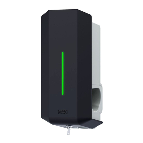
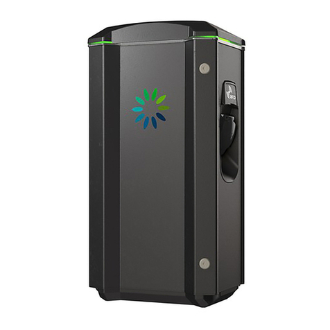
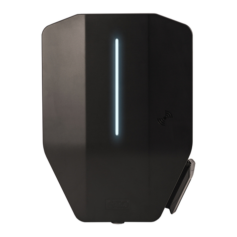
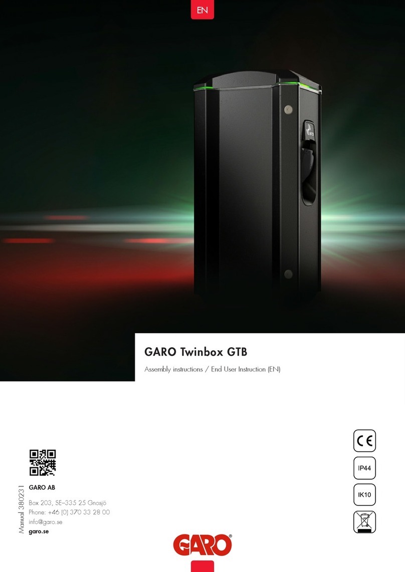
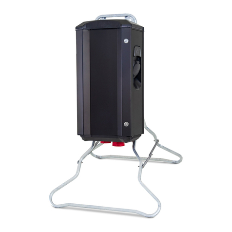
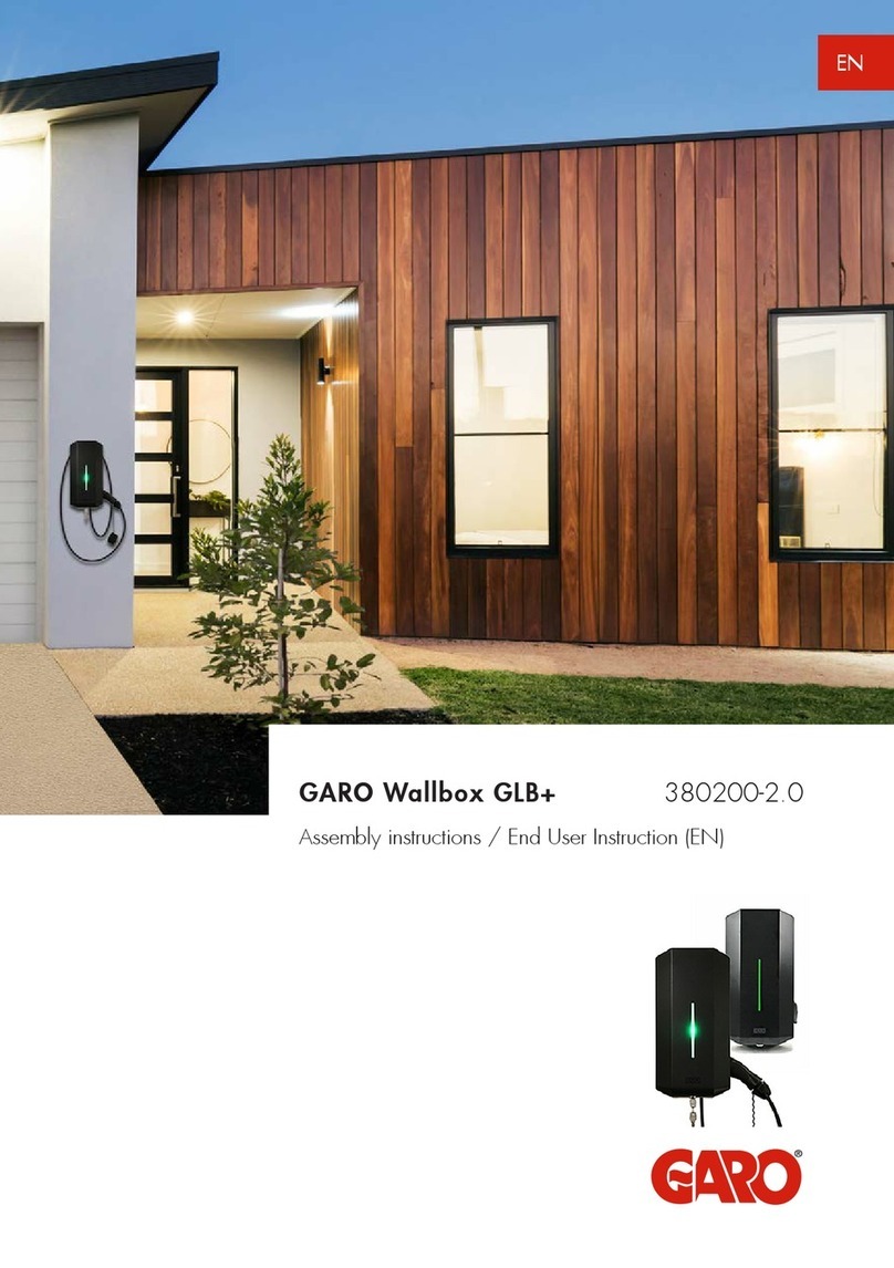
GARO Wallbox GHL User manual

EN
GARO Wallbox GHL
Assembly instructions / End User Instructions (en)
380175-5

2
EN
GARO Wallbox
D
A
E
C
B
A. Front cover
B. Cover
C. Back panel
D. Indication light
E. Key
F. Connector type 1 or 2
G. Type 2 socket outlet
H. RCCB (Residual Current Circuit Breaker) or RCBO (Residual Current Breaker with
Overcurrent Protection)
F
(figure 1)
with cable and connector, type 1 or 2

3
EN
GARO Wallbox
H
G
with type 2 socket outlet
(figure 3)
(figure 2)

4
EN

5
EN
TABLE OF CONTENTS
About this manual 7
Safety Information 8
Technical data 11
Mainboard Simplified Connetion Diagram 12
Dimensional drawing 13
Assembly instructions for installer 14
Box Contents 16
Tools and Materials Required 17
Step-by-Step Installation 18
Reducing the charging current 25
End User instruction 27
Charging electric vehicles 29
Resetting/Conditioning of RCCB or RCBO 31
Care 32
Troubleshooting 33
Index 34

6
EN

7
EN
About this manual
The purpose of this Manual is to provide you with the necessary information to charge
your electric vehicle using Garo Wallbox, models GHL.
This document contains general descriptions which are verified to be accurate at the time
of printing. However, because continuous improvement is a goal at GARO, we reserve
the right to make product modifications at any time.
About this manual

8
EN
Safety Information
Hazard categories and special symbols
Read these instructions carefully before trying to install, operate, or maintain it.
Save the manual for future use.
Indicates a potentially hazardous situation which could result in death or
serious injury
Indicates a potentially hazardous situation which could result in minor or
moderate injury
Indicates practices that do not involve the risk of bodily injury
Safety Information
Warnings
This equipment should not be used by anyone (including children) with reduced
physical, sensory or mental capacity, or anyone lacking in experience or
knowledge, unless they are provided with supervision or prior instruction in how
to use the equipment by the person responsible for their safety.
The GHL Wallbox range of charging stations is designed exclusively for charging
electric vehicles.

9
EN
Safety Information
The GHL Wallbox must be grounded through a permanent wiring system.
Do not install or use the GHL Wallbox near flammable, explosive, harsh, or
combustible materials, chemicals, or vapors.
Turn off input power at the circuit breaker before installing, configure or cleaning
the GHL Wallbox.
Use the GHL Wallbox only within the specified operating parameters.
Never spray water or any other liquid directly at the GHL Wallbox. Never spray
any liquid onto the charge handle or submerge the charge handle in liquid. Store
the charge handle in the dock to prevent unnecessary exposure to contamination
or moisture.
Do not use this equipment if it appears to be damaged or if the charging cable
appears to be damaged.
Do not modify the equipment installation or any part of the product.
Do not touch the GHL Wallbox’s end terminals with fingers or any other objects.
Do not insert foreign objects into any part of the GHL Wallbox.

10
EN
Safety Information
Cautions
Do not use private power generators as a power source for charging.
Incorrect installation and testing of the GHL Wallbox could potentially damage
either the vehicle’s Battery and/or the GHL Wallbox itself.
Do not operate the GHL Wallbox in temperatures outside its operating range –
see technical data.
Notes
All installation must be carried out by an authorised installer and comply with
local installation regulations.
Ensure that the GHL Wallbox’s charging cable is positioned so it will not be
stepped on, driven over, tripped on, or subjected to damage or stress.
Unroll the charging cable to prevent it from overheating.
Do not use cleaning solvents to clean any of the GHL Wallbox’s components.
The outside of the GHL Wallbox, the charging cable, and the end of the
charging cable should be periodically wiped with a clean, dry cloth to remove
accumulation of dirt and dust.
Be careful not to damage the circuit boards or components during installation.
Refer to local standards and regulations not to exceed charging current
limitations.
The front cover must always be locked in its upper position in order to ensure
compliance with IP Code IP44.
11
EN
Technical data
Specifications
Product type: all GHL models
Standards/directives: IEC 61851-1 and IEC TS 61439-7
Installation: on wall or on GARO Wallbox stand
Voltage rating: 230V/400 50Hz
Installation systems: TT, TN and IT systems
Charging type: Mode 3
IP classification: IP44
Mechanical impact
resistance:
IK08
Application temperature: -250C – +400C
Storage temperature: -350C – +550C
Installation height: 0.5–1.5 metres above ground/land to lower edge of
charger
Weight: around 3 kg including socket outlet
3.8–4.1 kg including cable and connector, 1-phase
5.4 kg including cable and connector, 3-phase
Cable length: 5 m (Only GLB models with fixed cables)
Technical data

12
EN
PE (Car)
Interlock on
socketoutlet
red
Motor
LED
RFID
Mode-
3
K101
K402
K302
K201
LED
RS-485
K401
Fuse FB
Contactor FB
Contactor Ctr
Contactor Ctr
PE
Socketoutlet/
Vehicle connector
RCCB
PE N L
1 2 3 4
ON
ON
1 2 3 4 5 6 7 8
N
L
PP
CP
Out +
Out -
FB
+12V
M
Mainboard Simplified Connetion Diagram
Mainboard Simplified Connection Diagram
Valid for 1- and 3-phase installation.
(figure 4)
(figure 13, page 25)

13
EN
205
124
422
Dimensional drawing
Dimensional drawing
(figure 5)

14
EN
Assembly instructions for installer
352460
GHL-T222WO-B
230/400V 32A 50Hz
IP44 EN 61851-1 IEC61439-7 AEVCS
SN: 5022254
BOX 203, 335 25 GNOSJÖ, SWE
All installation must be carried out by an authorised installer and comply with
local installation regulations.
Congratulations on selecting a GARO Wallbox and contributing to a better environment.
The GARO Wallbox is an AC charger enabling Mode 3 charging which complies fully
with the requirements of IEC 61851-1 and IEC TS 61439-7.
The product complies with IP Code IP44, with a closed front.
It is to be fitted to a wall or GARO Wallbox stand.
ASSEMBLY INSTRUCTIONS FOR INSTALLER
(figure 6)
Type Label example
GHL Type
Important information for installer:

15
EN
Assembly instructions for installer
(figure 6)
(table 1)
• Calculate to determine the maximum operating current. Use conductors that are sized
in accordance with local wiring regulations. The selected cable must be able to
sustain periods of constant load of up to 32A. Manufacturers recommendation is to
use minimum 10mm² conductors to avoid voltage drop.
• Calculate the distance to ensure minimal voltage drop.
1) Chargers without RCCB or RCBO included in the enclosure must have Residual
Current protection and must be protected with a max 32A fuse in the supply
distribution box.
2) Chargers without RCCB Type B fitted in the enclosure must in accordance to
IEC 60364-7-722 be protected with a Residual Current Device (RCD) Type B.
3) 3-phase chargers equipped with a Residual Current Circuit Breaker (RCCB)
must be protected with a max 32A fuse in the supply distribution box.
4) 1-phase chargers fitted with a Residual Current Breaker with Overcurrent
Protection (RCBO) can be connected in parallel. This group of chargers must
be protected by a backup fuse in the distribution box. The backup fuse shall
not exceed 125A.

16
EN
Assembly instructions for installer / Box Contents
EN
GARO Wallbox
Assembly instructions/User Instructions (EN)
380175-3
Box Contents
Language labels
GHL Wallbox
Keys
Drill template
(see the back of the box)
Manual

17
EN
Assembly instructions for installer / Tools and material required
Before installing the Garo Wallbox, gather the folllowing tools and materials:
• Pencil or marker
• Hole punch (optional, to push through cardboard template)
• Wire cutter
• Voltmeter or digital multimeter (to measure AC voltage at the installation site)
• Small flathead screwdriver
• Medium flathead screwdriver
• Large flathead screwdriver (optional, to remove plastic knock-outs)
• T20 Torx driver
• 3 screws (and plugs) suitable for wall type
• Ferrules (the diameter of the ferrule depends on the diameter of the power wiring and
the construction)
• Level
• Power drill
Tools and Materials Required

18
EN
Assembly instructions for installer / Step-by-Step installation
1. Read Safety Instructions
All installation must be carried out by an authorised installer and comply
with local installation regulations.
2. Ensure the supply cable is powerless.
Turn off input power at the circuit breaker before installing, configure or
cleaning the GHL Wallbox.
3. Remove the drill template from the packaging (refer Box Contents)
4. Attach the drill template to the wall where the charger will be installed.
Suitable height - refer Technical Data.
Do not install or use the GHL Wallbox near flammable, explosive,
harsh, or combustible materials, chemicals, or vapors.
5. Drill/mark in accordance with the instructions on the drill template.
6. Unlock the front cover with the key provided and slide the cover downwards.
7. The front cover has a built-in stop-position. To move past this position, grip the
underside of the cover and lift outwards gradually while pulling downwards.
Step-by-Step Installation
(figure 7)

19
EN
Assembly instructions for installer / Step-by-Step installation
8. Loosen the seven screws and carefully remove the cover from the back panel.
(figure 8)

20
EN
Assembly instructions for installer / Step-by-Step installation
Connection of phases for 3-phase
charger to 3-phase system as below.
When connecting a 3-phase charger to
1-phase system connect phase to L1.
(figure 9)
Table of contents
Other GARO Batteries Charger manuals

GARO
GARO Twinbox GTB Series User manual

GARO
GARO LS4 Wallmounted Supplement

GARO
GARO Wallbox GLB+ User manual

GARO
GARO Wallbox GLB User manual

GARO
GARO LS4 43kW User manual

GARO
GARO Wallbox GLB Series User manual

GARO
GARO Twinbox GTB User manual

GARO
GARO Castra User manual

GARO
GARO ENTITY PRO Owner's manual