1. Product Overview
Boost
Indicator
Boost
Button
On/Off
Switch
Timed on
Indicator
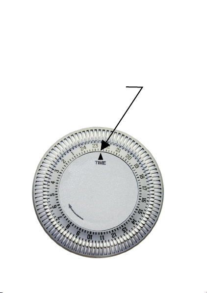
Clock with
Tappets
HEATER CONTROLLER AT A GLANCE
Fig. 1
2. Controls 3. Boost Function 4. Setting the clock
OP-ECOSAVE User Instructions
TIMED ON INDICATOR
The indicator glows when the ‘TIMED
ON’ output is active.
BOOST INDICATOR
The indicator glows if the ‘BOOST
SWITCH’ is used.
ON/OFF SWITCH
SWITCH IS IN ‘OFF POSITION’
The settings of the ‘TIMED ON’ and
‘BOOST’ time period are not activated
the clock runs but the heater is
Disconnected.
SWITCH IS IN ‘ON POSITION’
The settings of the ‘TIMED ON’ and
‘BOOST’ time period are activated and
the water will be heated during the
‘TIMED ON’ time period.
BOOST BUTTON
1. This button is only needed if you
need extra hot water during the day
time ‘ PEAK’ time.
2. Choose your boost time (adjustable
between 15 & 120 minutes). Press
the ‘BOOST BUTTON’ once for
switching ON.
3. If you want to interrupt the boost
function before the boost time is
completed: Press the ‘BOOST
BUTTON’ again.
CHANGING THE ‘TIMED ON’ PERIOD
To set the time on period, move the
tappets for the ‘TIMED ON’ time period
to the outer position of the dial. The
minimum switching time is 15 minutes.
Fig. 2
SETTING THE TIME OF DAY
Turn the dial in the direction of the arrow
(clockwise) until the correct time of day is
exactly opposite the time set marker on
the clock face (24 hr clock).