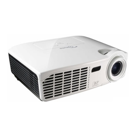
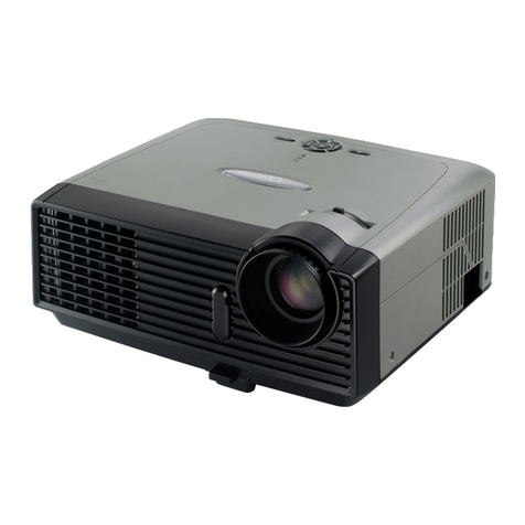
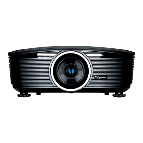
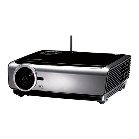
Optoma HD710 User manual

SERVICE MANUAL
SI : TSE: Check: Approved:
Date Revise Version Description
2008/2/3
V1.0 Initial Issue
HD71/HD710/HD75
Copyright February.2008. All Rights Reserved P/N: 36.8AE03G001
95.8AE01G00A ; 95.8AE01G019 ; 95.8AE01G001; 95.8AE01GC0A ; 95.8AE01GC0B ;
95.8AE01GC0C ; 95.8AE01GC0H ;95.8AE01GC0J ; 95.8AE01GC0L; 95.8AE01GC0T ;
95.8AE01GC1A ; 95.8AE02G019 ; 95.8AE02GC0E ; 95.8AE02GC0K
Corrine

HD71/HD710/HD75 Condential
II
HD71/HD710/HD75 Comparison List
HD75 HD71/HD710
DC.8AE02G001 D.C. HD710 DC.8AE01G001 D.C. HD71
70.8AE10G001
ASSY TYPE A ENGINE
MODULE HD71 70.8AE01G001
ASSY TYPE A ENGINE
MODULE HD71
70.8AE12G001
ASSY COLOR WHEEL
MODULE OERLIK 70.86V31G001
ASSY COLOR WHEEL
MODULE OERLIK
23.8AE19G021
COLOR WHEEL
R62G95B53R62Y35B53 23.87U19G011
COLORWHEEL
R90Y28G90C28W42B82,
70.8AE17G001
ASSY LAMP DRIVER
OSRAM 230W HD 70.87K04G001
ASSY LAMP DRIVER
OSRAM 230W EP
70.8AE15G001
OSRAM O3 MID 200W
LAMP DRIVER 70.87U06G001
OSRAM O3 MID 200W
LAMP DRIVER
39.8AE03G002
OSRAM RGBRYB 2X ,3x_
PAL WAVEFO 39.87J03G001
OSRAM 6S W42
WAVEFORM
70.8AE13G001 ASSY MB PCBA HD710 70.8AE02G001 ASSY MB PCBA HD71
80.8AE01G011
PCBA MAIN BD1 ENTEK
FOR HD710 80.8AE01G002
PCBA MAIN BD1 ENTEK
FOR HD71

HD71/HD710/HD75 Condential
III
Preface
This manual is applied to HD71/HD710/HD75 projection system. The manual gives you a
brief description of basic technical information to help in service and maintain the product.
Your customers will appreciate the quick response time when you immediately identify
problems that occur with our products. We expect your customers will appreciate the
service that you offer them.
This manual is for technicians and people who have an electronic background. Please
send the product back to the distributor for repairing and do not attempt to do anything that
is complex or is not mentioned in the troubleshooting.
Notice:
The information found in this manual is subject to change without prior notice. Any
subsequent changes made to the data herein will be incorporated in future edition.
HD71/HD710/HD75 Service Manual
Copyright February.2008
All Rights Reserved
Manual Version 1.0

HD71/HD710/HD75 Condential
IV
Table of Content
Chapter 1 Introduction
Highlight 1-1
Compatible Mode 1-2
Chapter 2 Disassembly Process
Equipment Needed & Product Overview 2-1
Disassemble Top Cover 2-2
Disassemble Keypad Board,Keypad and FPC Cable 2-3
Disassemble Lamp Module 2-4
Disassemble I/O Cover 2-4
Disassemble Top Shielding 2-5
Disassemble Main Board Module,Audio Board Moudle and
Component Module 2-6
Disassemble Left Cover and Right Cover 2-7
Disassemble Fan Module 2-8
Disassemble LVPS Module 2-9
Disassemble Engine Module 2-10
Disassemble Thermal Switch,Blow Duct Rubber 2-11
Disassemble Color Wheel and Photo Sensor Board 2-12
Disassemble DMD Chip and DMD Board 2-13
Disassemble Zoom Ring 2-14
Disassemble Focus Ring 2-15
Disassemble ROD Module 2-16
Disassemble Blower Module 2-17
Disassemble Limit Switch 2-18

HD71/HD710/HD75 Condential
V
Disassemble Engine Mask Plat and Lamp Driver 2-19
Disassemble System Support Shielding Module 2-20
Disassemble Speaker 2-21
Disassemble Lens Case,Lens Door,Lens Door Switch 2-22
Disassemble IR Board,IR Lens 2-23
Chapter 3 Troubleshooting
LED Lighting Message 3-1
Main Procedure 3-2
Chapter 4 Function Test & Alignment Procedure
Test Equipment Needed 4-1
Service Mode 4-1
OSD Reset 4-1
Test Condition 4-2
Test Inspection Procedure
4-4
PC Mode
4-4
Video Performance
4-8
Optical Performance Measure
4-10
Others4-11
Chapter 5 Firmware Upgrade
Equipment Needed 5-1
DLP Composer Lite Setup Procedure 5-2
USB Driver Upgrade Procedure 5-4
Firmware Upgrade Procedure 5-5
Chapter 6 EDID Upgrade
EDID Introduction 6-1
Equipment Needed 6-2

HD71/HD710/HD75 Condential V
Setup Procedure 6-3
EDID Key-In Procedure 6-3
Appendix A Exploded Overview I
Appendix B Serial Number System Denition XX
PCBA Code Denition XXI

HD71/HD710/HD75 Condential 1-1
Chapter 1
Introduction
1-1 Highlight
No Item Description
1Dimension (WxDxH) - 295x222x95.7mm
2 Weight - 6.5lbs Max
3Power Supply - Input 100-240V, 50-60 Hz
4 Resolution - Native resolution 1280x720
5Brightness
- 2000 lumens (typical) ( HD71/HD710)
- 1750 lumens (minimum) (HD71/HD710)
- 1100 lumens (typical) (HD75)
- 990 lumens (minimum) (HD75)
6 Contrast - 1800:1 full on/off (typical)
- 1300:1 full on/off (minimum)
7Uniformity - Typical : 80%
- Minimum : 65%
8 Throw ratio - 1.55 ~1.70:1 distance/width
9 Lamp life
- 100% Power 1500 hrs,50% survival rate with 50% lumen
maintenance
- 85% Power 2000 hrs,50% survival rate with 50% lumen
maintenance
10 Color wheel
- 6 segments R90G90B82C28Y28W42 3x speed (HD71/
HD710)
- 6 segments R62G95B53R62Y35B53 2x speed (HD75)
11 Lamp - OSRAM 200W Lamp

HD71/HD710/HD75 Condential
1-2
No Item Description
12 Temperature
- Operating: 5-35 °C, 80% humidity
- Storage: -20 - 60 °C, 80% humidity
- Altitude: 5-35°C @ 0 - 2,500 ft
5-30°C @ 2,500 - 5,000 ft
5-25°C @ 5,000 - 10,000 ft
- Maximum storage altitude 40,000 ft
13 Video compatibility
- NTSC NTSC M/J, NTSC 4.43
- PAL PAL B/D/I/G/H, PAL M, PAL N
- SECAM SECAM B/D/G/K/L
- SDTV 480i, 480p, 576i, 576p
- HDTV 720p 50\60Hz, 1080i 50\60Hz,
1080p 24\50\60H
14 I/O
- HDMI 1.3 x1
- YPbPr (RCA) x1 Must Have 3 x RCA component input
- D-sub RGB x1
- DVI-D w/HDCP x1
- Composite x1
- S-video x1
- USB x1 (For quick FW upgrade)
- RS232 (3pin) x1
- 12 Volt Trigger x1
- Audio Input 3.5mm stereo jack socket x3 (1 audio in for
composite & svideo,1 audio in for VGA & DVI and 1 audio in
for component)

HD71/HD710/HD75 Condential 1-3
1-2 Compatible Mode
Analog
Compatibility Resolution V-Sync [Hz]
VGA
640x480 60
848x480 60
720x400 70
SVGA 800x600 56
800x600 60
XGA
1024x768 50
1024x768 60
1024x768 70
WXGA
1280x768 50
1280x768 60
1280x768 70
HD
1280x720 50
1280x720 60
1920x1080 50
1920x1080 60
SXGA
1280x1024 50
1280x1024 60
1280x1024 70
SXGA+ 1400x1050 60
MAC 1152x870 75.06
MAC G4 640x480 60
i Mac DV 1024x768 75

HD71/HD710/HD75 Condential 1-4
Digital
Compatibility Resolution V-Sync [Hz]
SVGA
800x600 60
800x600 72
800x600 75
848x480 60
XGA
1024x768 50
1024x768 60
1024x768 70
1024x768 75
Wide
1280x720 24
1280x720 50
1280x720 60
1920x1080 24
1920x1080 50
1920x1080 60

HD71/HD710/HD75 Condential 2-1
Chapter 2
Disassembly Process
2-1 Equipment Needed & Product Overview
1. Screw Bit (-) :107
2. Screw Bit (+) :107
3. Hex Sleeves 5 mm
4. Hex Sleeves 8 mm
5. Tweezers
6. HD71/HD710/HD75 unit
* Before you start: This process is protective level II. Operators should wear electrostatic chains.
* Note: 1. If you need to replace the main board, you have to get into service mode and record the
lamp usage hour.
2. Take HD71 as an example, HD710/HD75 is the same with HD71

HD71/HD710/HD75 Condential 2-2
2-2 Disassemble Top Cover
1. At “OPEN” mark,pull the Top Cover
to left side ( as yellow arrow)
2. Unscrew 5 screws
(as red circle)
3. Disassemble 1 FPC cable to
disassemble Top Cover
(as green square)
Note: There are 8 tenons
(as yellow circle)

HD71/HD710/HD75 Condential 2-3
2-3 Disassemble Keypad
Board,Keypad and FPC
cable
1. Unscrew 2 screws
(as red circle)
2. Unplug 1 connector to disassemble FPC
cable (as red square)
3.Separate all parts of the Keypad and Key
pad Board
Note: There are 2 tenons
(as yellow square)

HD71/HD710/HD75 Condential 2-4
2-5 Disassemble I/O Cover
1. Unscrew 4 hex screws
(as red circle)
2. Disassemble I/O cover
2-4 Disassemble Lamp
Module
1. Unscrew 2 screws
(as red circle)
2. Disassemble Lamp Module

HD71/HD710/HD75 Condential 2-5
2-6 Disassemble Top
Shielding
1. Unscrew 3 screws
(as red circle)
2. Disassemble Top Shielding

HD71/HD710/HD75 Condential 2-6
2-7 Disassemble Main Board
Module , Audio Board
Module and Component
Board Module
1. Unscrew 4 screws
(as red circle)
2. Unplug 8 connectors
(as yellow square)
3. Unplug 1 connector
(as blue square)
4. Disassemble Main Board Module
5. Unscrew 2 screws
(as yellow circle)
6. Unplug 1 connector
(as green square)
7. Disassemble Audio Board Module
8. Unscrew 2 screws
(as blue circle)
9. Unplug 1 connector
(as red square)
10. Disassemble Component Board Module

HD71/HD710/HD75 Condential 2-7
2-8 Disassemble Left Cover
and Right Cover
1. Release 3 tenons on the left side
(as yellow square)
2. Disassemble Left Cover
3. Release 3 tenons on the right side
(as red square)
4. Disassemble Right Cover

HD71/HD710/HD75 Condential 2-8
2-9 Disassemble Fan Module
1. Unscrew 3 screws
(as red circle)
2. Disassemble Fan Module
3. Unscrew 4 screws
(as yellow circle)
4. Disassembel Fan and Bracket
A
A

HD71/HD710/HD75 Condential 2-9
2-10 Disassemble LVPS
Module
1. Unscrew 1 ground screw
(as yellow circle)
2. Unscrew 4 screws
(as green circle)
3. Disassemble Bracket and Mylar
4. Unplug 3 connectors
(as yellow square)
5. Disassemble LVPS Module

HD71/HD710/HD75 Condential 2-10
2-11 Disassemble Engine
Module
1. Unscrew 1 screw
(as yellow circle)
2. Disassemble Inner Mask
3. Unscrew 4 screws
(as red circle)
4. Disassemble Engine Module
A
B
AB
This manual suits for next models
2
Table of contents
Other Optoma Projector manuals

Optoma
Optoma GT200 User manual

Optoma
Optoma Optoma TX615 User manual

Optoma
Optoma EH505e-B User manual

Optoma
Optoma HD81-LV Technical manual

Optoma
Optoma PlayTime PT105 User manual

Optoma
Optoma EW536 User manual

Optoma
Optoma EzPro 739 User manual

Optoma
Optoma H30A User manual

Optoma
Optoma GT760 User manual

Optoma
Optoma W515T User manual

Optoma
Optoma TW610 User manual

Optoma
Optoma Optoma EX530 User manual

Optoma
Optoma EX540 User manual

Optoma
Optoma Theme Scene HD82 User manual

Optoma
Optoma Optoma PRO150S User manual

Optoma
Optoma EP783S User manual

Optoma
Optoma EP731 User manual

Optoma
Optoma EP780 User manual

Optoma
Optoma TX783L User manual

Optoma
Optoma TW675UST-3D User manual