Optomed Smartscope PRO User manual

Page 1 of 51
Optomed SMARTSCOPE PRO & SMARTSCOPE FA are manufactured by
Optomed Ltd.
Place of Business:
Optomed Ltd
Yrttipellontie 1
FI-90230 Oulu
Finland
Manual version: Rev 17.0
Date: 2019 09 30
USER’S MANUAL
Optomed Smartscope PRO
& Smartscope FA

Page 2 of 51
This manual describes guidelines for the following modules:
Model:
Description:
Accessories
Smartscope M5
medical digital camera
Smartscope EY4
module for retinal imaging
eye cup, quick user guide
Smartscope FA
module for fundus fluorescein angiography
imaging
eye cup, quick user guide
Smartscope ES2
module for anterior ophthalmic imaging
Smartscope Cradle V1
for data transmission and battery charging
USB cord
Power unit
If not all optics modules were purchased then the sales case does not include them or the accessories
related to that optics module.
In addition, the sales case includes:
-Batteries (2 pcs)
-Cleaning cloth
-User manual
-USB memory stick (Includes training material, Optomed Orbit software and user manual, and
Optomed Client PC software in case device has WLAN functionality).
The following accessories can be purchased separately:
-Optomed Slit Lamp Adapter that enables the camera to be used as stationary imaging tool.

Page 3 of 51
Quick start guide
WHAT TO DO BEFORE THE FIRST USE:
1. Remove Optomed Smartscope M5 from the sales
package and check that all parts are undamaged.
2. Install Battery as instructed in the Appendix B.
3. Place Cradle on a desk next to the PC (Personal
Computer).
4. Connect the USB cable to the PC.
5. Connect power unit to the wall plug (mains)
6. Place Optomed Smartscope M5 to the cradle. Battery
starts to charge. Charge battery for 4 hours before the
first use. When device is not used, it may be stored in
the Cradle.
7. Camera will not automatically power up in the cradle without the charger. User needs to press
the power button.
Guideline for placing the camera to the cradle:
Camera will fit to the cradle when it’s hold straight while placing it. Excessive force shall be
avoided in order to prevent the camera and cradle connectors from breaking.
Guideline for battery and device storage:
If battery is stored out of the camera for longer period of time, ensure that battery is fully
charged before storage. During storage battery shall be re-charged occasionally (e.g. every
3-9 months).
If battery is stored in the camera, camera shall be placed in the cradle with cradle power
cable connected.
Device is not allowed to be used when battery cover is open.
Normal battery life time is expected to be 1-2 years.

Page 4 of 51
Table of contents
Quick start guide .............................................................................................................................3
Table of contents.............................................................................................................................4
1. Indications for use................................................................................................................5
2. Contraindications for use of the optics modules EY4, FA and ES2 ......................................6
3. Warnings and cautions.........................................................................................................7
4. Important symbols ...............................................................................................................8
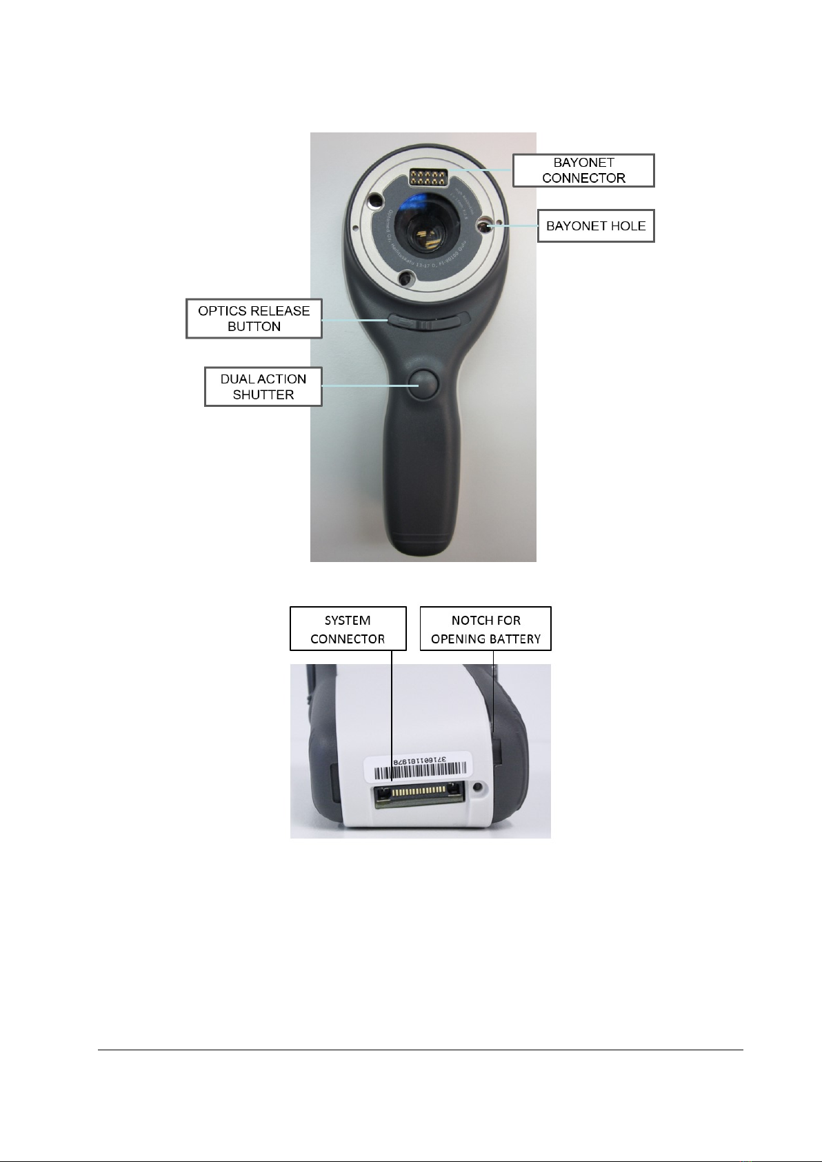
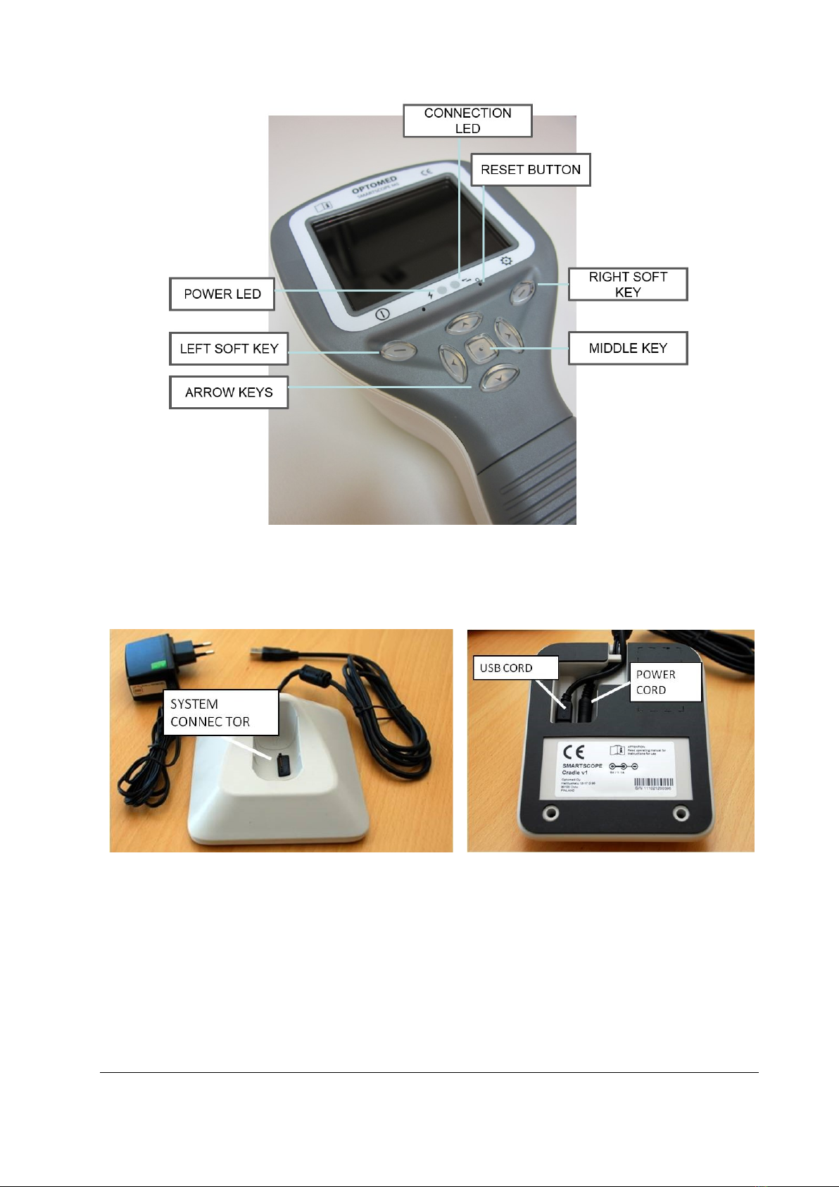
5. Parts of the device................................................................................................................9
6. Usage environment requirements.....................................................................................12
7. Operating instructions........................................................................................................13
7.1. Preparations ...................................................................................................................13
7.2. Connection to a PC .........................................................................................................13
7.2.1. Pay-per-study ..........................................................................................................13
7.3. Basic use –starting up, shutting down and taking an image.........................................14
7.3.1. Image quality analysis .............................................................................................14
7.4. Attaching and detaching optics module.........................................................................15
7.5. Device Menu...................................................................................................................15
7.6. Patient editor..................................................................................................................18
7.6.1. Adding new patient.................................................................................................18
7.6.2. Patient folder linking...............................................................................................19
7.6.3. Patient list exporting ...............................................................................................19
7.7. Adjusting focus and automatic focus .............................................................................19
7.8. Reset button ...................................................................................................................19
8. Retinal imaging using optics module Smartscope EY4 ......................................................20
9. Eye imaging using anterior ophthalmic module Smartscope ES2 .....................................25
10. Fluorescein Angiography imaging using optics module Smartscope FA............................29
11. Error messages...................................................................................................................34
12. Cleaning instructions..........................................................................................................35
13. Device maintenance...........................................................................................................36
14. Technical description .........................................................................................................37
15. Warranty ............................................................................................................................42
Appendix A - Electromagnetic compatibility information ............................................................43
Appendix B - Replacing the battery...............................................................................................46
Appendix C - WLAN functionality..................................................................................................47
Installing / Uninstalling..............................................................................................................47
Operation ..................................................................................................................................47
WLAN SD card firmware update ...............................................................................................50

Page 5 of 51
1. Indications for use
Smartscope M5 is a medical digital camera that is used with dedicated optics lens intended to take images
of the eye fundus and surface of the eye.
Supported optics lenses and their intended uses are:
Model:
Description:
Smartscope EY4
Optomed Smartscope M5 digital camera with EY4 optics module is
intended to capture digital images and video of the fundus of the
human eye.
Smartscope FA
Optomed Smartscope M5 digital camera with FA optics module is
intended to capture digital images of the fundus angiograms of the
human eye.
Smartscope ES2
Optomed Smartscope M5 digital camera with ES2 optics module is
intended to capture images and video of the surface of the human eye
and surrounding areas.
The device may only be operated by persons who have been properly trained or who have the required
knowledge and experience to do so.
Smartscope M5 with optics modules is a prescription device: Federal law restricts this device to sale by or
on the order of a physician or licensed practitioner.

Page 6 of 51
2. Contraindications for use of the optics modules EY4, FA and ES2
Because prolonged intense light exposure can damage the retina, the use of the device for ocular
examination should not be unnecessarily prolonged, and the brightness setting should not exceed what
is needed to provide clear visualization of the target structures.
The retinal exposure dose for a photochemical hazard is a product of the radiance and the exposure time.
If the value of radiance were reduced in half, twice the time would be needed to reach the maximum
exposure limit.
While no acute optical radiation hazards have been identified for direct or indirect ophthalmoscopes, it is
recommended that the intensity of light directed into the patient's eye be limited to the minimum level
which is necessary for diagnosis. Infants and persons with aphakia or diseased eyes will be at greater risk.
The risk may also be increased if the person being examined has had any exposure with the same
instrument or any other ophthalmic instrument using a visible light source during the previous 24 hours.
This will apply particularly if the eye has been exposed to retinal photography.
Smartscope EY4, FA and ES2 are classified as Group 2 based on standard ISO 15004-2:2007. The daily
usage time and maximum allowed number of pulses is calculated based on optical classification results
according to standard ISO 15004-2:2007.
WARNING:
The light emitted from this instrument is potentially hazardous. The longer the
duration of exposure and the greater the number of pulses, the greater the risk of
ocular damage. Exposure to light from this instrument when operated at maximum
output will exceed the safety guideline after:
Maximum number of pulses (still images) allowed daily:
-EY4: 6300 pulses (still images) / eye
-FA: 5000 pulses (still images) / eye
-ES2: 250 pulses (still images) / eye
Or alternatively
Total daily usage time for continuous light (= video usage time + aiming light duration)
shall be limited to:
-EY4: 1 h 30 min video usage / eye
-ES2: 8 min video usage / eye

Page 7 of 51
3. Warnings and cautions
Place PC and cradle outside the patient environment (at least 1.5 meters distance from the
patient).
Use only accessories and battery provided by Optomed with this product.
Connection between camera and workstation is USB and/or WLAN. Any authorization
procedures should be carried out in workstation.
Images and videos can be copied from camera to workstation via USB and/or WLAN and
then viewed in workstation.
USB write protection is on by default. When protection is on this feature will prevent
writing to camera memory card from PC when connected to the cradle. In case device has
WLAN functionality, USB write protection must be turned off.
USB connection works without power cable. There is no USB charging in M5
No modification of this equipment is allowed.

Page 8 of 51
4. Important symbols
Symbol
Description
European certificate of conformity
CE marking with notified body identification numbering indicates
the conformity of 93/42/EEC Medical Device Directive for class IIa
devices and CE marking without notified body identification
numbering indicates the conformity of 93/42/EEC Medical Device
Directive for class I devices.
Read accompanying user documentation indicates that important
operating instructions are included in this User’s and Maintenance
Manual. Failure to follow these instructions could place the patient
or operator at risk.
Type BF applied parts.
Applied part is a part of Smartscope that in normal use necessarily
comes into physical contact with the patient.
9 V, 1.1 A
Charger polarity symbol, voltage and power
Interference may occur in the vicinity of equipment (in case device
has WLAN functionality).
Prepare the device for reuse or separate collection as specified by
Directive 2002/96/EC of the European Parliament and Council of the
European Union on Waste Electronic and Electrical Equipment
(WEEE). If this product is contaminated, this directive does not
apply.
WARNING
Indicates a hazardous situation which could result in patient injury,
harm or death if the appropriate safety precautions are not
followed.
CAUTION
Indicates a situation which could result in device harm, damage or
mal-function if the appropriate cautions / precautions are not
followed.

Page 9 of 51
5. Parts of the device

Page 10 of 51
Cradle:

Page 11 of 51
Soft key indicators:
Position
Indicator
Purpose
Left soft key
To power on the device
To power off the device, with long press
Right soft key
Open menu with long press
LED indicators:
The recharging and connection to PC is indicated with green (charging) and blue (connection) LED-lights:
Position
Indicator
Purpose
Left LED-indicator
Green
Active when device is powered on, blinking when charging in
cradle.
Right LED-indicator Blue
Active when devices is placed to the cradle and connected to a
PC.
Graphical indicators:
These indicators are displayed on the top row of the display during imaging:

Page 12 of 51
6. Usage environment requirements
WARNING
Smartscope is not suitable for use in the presence of flammable anesthetics.
WARNING
Place PC and cradle outside the patient environment (at least 1.5 meters distance from
the patient).
CAUTION
Smartscope is intended to be used inside in a normal room temperature and normal
humidity. Do not use Smartscope in an environment where there is possibility that
water condenses to or inside the Smartscope.
CAUTION
If the PC is connected to a customer network make sure to apply appropriate safety
measures, such as Antivirus and Firewall protection.
CAUTION
It is only allowed to attach USB cable and Power source provided in the sales package
into the cradle. If you need replacement to the USB cable or Power source please
contact Manufacturer or your own Retailer.
USB Cable must be connected only to the USB port of a PC computer that complies
with the IEC 60950 standard. Avoid using excessive power or twisting the connector
when connecting the USB cord to a PC.
To transfer patient image data the device must be used together with a PC (Personal Computer) running
either Microsoft Windows 7®, Windows 8.1® and Windows 10®. The device does not need any drivers to
be installed on a PC.
Writing to the memory card from PC is not enabled by default.
Device shall be used according to this manual, quick reference guide and / or information found on
Optomed website www.optomed.com.
Electromagnetic compatibility information and recommended separation distances between portable
and mobile RF communications equipment and the Optomed Smartscope are given in the Appendix A.

Page 13 of 51
7. Operating instructions
This chapter gives instructions for using the device. More specific instructions for using optics lenses are
given in the optics lens specific chapters.
7.1. Preparations
Smartscope is both charged and connected to PC (Personal Computer) using the provided cradle. When
Smartscope is not used, it may be stored in the cradle. Storing device in the cradle is not harmful for the
battery.
Device can be connected to the cradle with optics attached.
7.2. Connection to a PC
Image data transfer method to PC is similar as with a digital camera.
When connected to a PC running Microsoft Windows 7®, Windows 8.1®
or Windows 10® operating system displays query for AutoPlay. It is
possible to select appropriate image viewing program or simply open
the folder to view and then store files to the hard disk of the PC.
Writing to the memory card from PC is not enabled by default.
In case device has WLAN functionality, USB write protection must be turned off. WLAN enables wireless
image transfer from camera to PC. Image transmission system is shown below:
Instructions how to establish WLAN connection with Optomed Client refer to Appendix C.
7.2.1. Pay-per-study
In case camera is in pay-per-study mode, images can be viewed only with Optomed Workstation Software.
There are no other changes in camera functionality.

Page 14 of 51
7.3. Basic use –starting up, shutting down and taking an image
Device is powered on by pressing left soft key.
It is possible to capture both still images and video. Image capture mode is changed from camera menu
(optics specific tab) that opens by pressing right soft key for 1s.
Still image is captured using the dual action shutter to the second position. Video is captured by keeping
the dual action shutter pressed down in the second position.
Taken image will stay on display until it is cleared by pressing right or left soft key. Image can be zoomed
in instant preview by pressing middle key. There are four zoom levels. Pressing middle key activates the
next level. Move around the image by using arrow keys.
To transfer images to a PC via USB connection, place device to the cradle. The image transfer and charging
is indicated with green and blue LED-lights and text on LCD-screen. In case the WLAN connection is active
images are transferred to the PC automatically.
NOTE:
If images are corrupted or not transferred to the PC, the original images are saved to the
memory card. Please try again to transfer images to the PC via USB.
Smartscope verifies if image data is erased either when device is powered on from power off mode or
power save mode or when device is removed from the cradle. It is recommended that image data storage
is always erased with a new patient.
Device is powered off by keeping left soft key pressed down over 1 second.
NOTE:
When device is powered on, powered off or goes to standby mode the camera focus motor
may make a sound. This sound is normal and is not a sign of any damage or problem.
7.3.1. Image quality analysis
After capturing an image, the image quality analysis is performed if image quality analysis is enabled from
optics menu. The results of image quality analysis are shown in instant review with the image. Letter B
represents the brightness of the image. If the brightness of the image is good, the indicator is shown as
green. The indicator is shown as yellow, if the image is little bit over or under exposed. If the image is
severely over or under exposed the indicator is shown as red.
Letter Rrepresents reflections and shadowing. If the image
has no reflections or shadowing, the indicator is shown as
green. The indicator is shown as yellow, if the image has small
reflections or shadows. If the image has large reflections or
shadows, the light is red.
Letter Srepresents sharpness. If the image is sharp, the
sharpness value is green. The indicator is yellow, if the image
is not sharp enough. For un-sharp image, the indicator light is
shown as red.

Page 15 of 51
7.4. Attaching and detaching optics module
NOTE:
Optic modules used with Optomed Smartscope M5 must include text “SMARTSCOPE”. It is
not allowed to attach other objects to the bayonet connector.
Optics is attached by placing it in front of the bayonet area of the device. Three bayonet legs are placed
on the holes and optics is pressed firmly to the device:
Optics is released by sliding release button that is located in front of the device above the dual action
shutter:
7.5. Device Menu
Menu is opened by pressing right soft key for 1s.
Menu has different tabs. One is for device settings such as
language selection. There is one tab for retinal imaging (EY),
fundus angiogram imaging (FA) and anterior eye imaging
(ES).
Arrow keys are used to move between tabs: use arrow key
up until tab is active and use left and right arrow keys to
change active tab. Light blue color indicates active tab.
Arrow keys change values in the menu. Active value is indicated with light blue color. Changed values
are saved by using left soft key (“Ok”) and cancelled by pressing right soft key (“Cancel”). Some values
are confirmed by pressing the Middle key.

Page 16 of 51
Table below includes explanations of the Device settings tab:
Setting
Values (default bolded)
Purpose
Preview images
Ok
To preview the images on camera press middle button.
New patient folder
Ok
To create a new patient folder press middle button. New
patient folder can also be created in live view by long
pressing the middle key.
Erase image memory
Ok
Select middle button to erase images and videos from
camera SD card.
Edit patient list
Ok
Press middle key to edit patient list
Patient information
On/Off
Enable or disable patient information linking
Display brightness
Low-Med-High
Use left and right arrow keys to adjust display brightness
Icons
On/Off
Show graphical icons when imaging.
Sounds
On/Off
When enabled, sound is played during image capture
Keyboard backlight
On/Off
When enabled, keyboard illumination is on
Select language
ENG-FIN-FRA-GER-ITA-
JPN-POR-SPA-ZHO
Use left and right arrow keys to select camera language
USB write protection
On/Off
When enabled, writing to SD card is not allowed when
device is in cradle. This feature helps prevent any viruses
getting from PC to the camera. Note that if device contains
WLAN card, during its setup or updating of its firmware,
USB write protection need to be temporarily set off.
Video file format
MPEG4/MPEG1
Use left and right arrow keys to select video file format
Image transfer
method
UMS/WIA
Use WIA for automatic and UMS for end-user activated
image transfer. UMS can be used in most cases.
Restore factory
Setting
Ok
To restore all settings menus to factory defaults. Activate
using the middle key. Note that also Wireless password is
restored to default.
SD card firmware
update mode
Ok
To start SD card firmware update mode, press middle
button.
Date
DD-MM-YYYY
Use up and down arrow keys to set date.
Time
HH:MM
Use up and down arrow keys to set time.
Camera SW version
Show camera SW version
Browse version information with left and right arrow key
Start query
Era./Fol./None
Choose the startup query between memory erase, new
patient folder or no query at all.
Wireless
On/Off
Enable or disable wireless connection
Wireless info
Ok
To view ‘WLAN SSID’ and ‘WLAN Password’, press middle
button.
Preview images
Image preview is opened by selecting “Preview files” with a middle key. Images are browsed by using
arrow keys. Display gives information about usage of the image preview.
Image can be zoomed while previewing by pressing middle key. Move around the image by pressing arrow
keys. Change between the four zoom levels by pressing middle key.
Patient ID information can be edited in image browser.

Page 17 of 51
New Patient Folder
A new patient folder is created by pressing middle key when the new patient folder selection is active in
Device menu. A new patient folder can also be created by pressing Middle key for 3 seconds when in live
view. If the current patient folder is empty a new folder cannot be created.
Erase Image Memory
Image memory can be erased by selecting “Erase Image Memory” in Device menu. This selection is
activated by pressing middle key. The camera also prompts the question “Erase image memory?” when
camera is powered on or removed from cradle.
Edit patient list
User can add or remove patients from patient list.
Patient information
Enable or disable patient information linking.
Display brightness
The Display brightness selection has three options: low, medium and high. Choose the suitable level of
display brightness according to for example how the examination room is lit up.
Icons
The icons shown on camera screen can be enabled or disabled to the user’s liking. The most essential
icons such as Menu icon are always visible.
Sounds
By default the camera makes a sound during image capture. This sound can be turned off from Device
menu.
Keyboard backlight
By default the camera keys have a backlight lit up when the camera is turned on. This light can be turned
off from Device menu if it disturbs the user while taking images.
Language
Camera has nine (9) different languages the user can choose from. Default language is English and the
language selection is always shown in English in menu. If language is changed camera has to be re-started.
USB write protection
USB write protection is on by default. When protection is on this feature will prevent any virus from
entering the camera from a PC when connected to the cradle. In case device has WLAN functionality, USB
write protection must be turned off.
Video file format
Camera has two file formats that user can choose for videos: MPEG4 and MPEG1. MPEG4 is a higher
quality file format but may not be viewed with all video players. MPEG1 format is more widely supported
by different SW applications.
Image transfer method
There are three options for the image transfer method: UMS (USB Mass Storage), WIA (Windows Image
Acquisition) and WLAN.
NOTE: WLAN supported only if device has WLAN functionality.

Page 18 of 51
Restore factory settings
Press middle key to restore factory defaults selection. Note that also Wireless password is restored to
default.
SD card firmware update mode
In case the device has WLAN functionality, SD card firmware can be updated by pressing middle button.
The device must be placed on cradle for SD card firmware update. If PC prompts a message to insert the
SD card, press any camera key to continue update. For more specific instructions, see Appendix C.
Date
Press middle key to change date settings. Date can be set using the up and down arrow keys. Move
between day, month and year by pressing the left and right keys. Date format is DD MM YYYY for Finnish,
German, French, Italian, Spanish and Portuguese. Date format is MM DD YYYY for Japanese and Chinese.
Time
Press middle key to change time settings. Time can be set using the up and down arrow keys. Move
between hours and minutes by pressing the left and right arrow keys.
Camera SW version
This item in Device menu tells the camera SW version.
Start query
User can choose start-up query between erasing images, creating new patient folder or no query at all.
When erasing images is chosen as the query the camera will prompt user on start-up whether all images
and videos shall be deleted. When new patient folder query is chosen the camera will ask if a new patient
folder shall be created upon start-up to prevent from mixing images with previous patient. If no query is
selected then camera will go directly to live view upon start-up.
Wireless
By default, wireless connection is on. User can enable or disable wireless connection. When wireless
connection is enabled, the wireless symbol is shown on display next to the battery level indicator.
Wireless info
Press middle key to view wireless connection information. ‘WLAN SSID’ and ‘WLAN Password’ are shown.
7.6. Patient editor
Patient information usage can be enabled / disabled. There can be maximum 500 patients on the list.
Name of the patient is shown in low right hand side above right soft key, if current folder is linked to a
patient.
7.6.1. Adding new patient
User can add new patient from Device menu by selecting Edit Patient list. User can add Patient ID and
Patient name after choosing New patient. New patient can be added also after creating new folder.

Page 19 of 51
7.6.2. Patient folder linking
User can link or unlink patient to/from current folder (not earlier ones). It is possible to link 5 folders to
each patient.
Linking can be done:
1. After erasing image memory, choose ‘yes’ when camera asks to ‘choose patient for the folder’.
2. Choosing Link in image browser, when folders and files are visible. Link key is grey and
unresponsive if current folder is not chosen. After folder is linked to a patient, folder is named by
the patient.
3. After creating new folder by long pressing middle key or from menu, choose ‘yes’ when camera
asks to ‘choose patient for the folder’.
NOTE: Exiting from image browser is done by pressing left key.
7.6.3. Patient list exporting
User can export patient list via WLAN. New file is created containing patient list with 16 kBytes of padding
bytes added to the end of file. File is named pehhmmss.jpg (hh is current hours, mm minutes and ss
seconds). File is written under DCIM folder in SD card. File is exported over WLAN.
Patient list can be exported also via USB. Patient list is written as text file (patexp.txt) to SD card root. If
patient list is modified in camera (new patient created) or SD card is erased, patient list is updated.
7.7. Adjusting focus and automatic focus
Camera has an autofocus function where camera finds correct focus place automatically. For EY4 and FA
square indicator appears when focusing is finished. For ES2 focus window turns green when focusing is
finished. Automatic focusing start when shutter button is pressed half way down. Focus mode can be
changed by pressing right soft key.
Image focus can be adjusted manually by pressing arrow keys up and down. When focus mode is set to
manual a diopter scale is visible on the screen.
7.8. Reset button
Reset button can be used if device behavior is abnormal.
Reset button is located in a small opening under display.
Button is marked with circle.
Reset button can be pressed with a thin object such as a paper clip.
Button needs to be pressed for over 7 seconds.

Page 20 of 51
8. Retinal imaging using optics module Smartscope EY4
Optomed Smartscope EY4 digital ophthalmic camera is intended to capture digital images and video of
the fundus of the human eye. The device set for retinal imaging consists of:
•Camera handset M5
•Attachable ophthalmic lens EY4
•Eye cup for EY4
•Cradle for charging and image transfer
Smartscope EY4 is intended for non-mydriatic imaging. This means that infrared is used for targeting
image to the eye fundus and visible light is flashed when image is taken. Pupil does not respond to the
infrared light so examination is convenient for the patient. Constant illumination can be selected from
device menu if mydriatic drops are used. Pictures can also be taken using infrared light for both aiming
and capturing.
Smartscope EY4 has 9 internal fixation targets for the patient to fixate at while imaging. Below section will
guide how to control the fixation lights.
STEPS FOR RETINAL IMAGING:
1. The examination room should be as dark as possible.
2. Both the patient and the examiner shall be seated while taking the images.
3. Either autofocus or manual focus can be used. Autofocus range is -15 to +10 diopters.
If patient has a refractive error and autofocus is off, focus need to be adjusted:
•Hyperopia: camera is focused to distance by pressing arrow key up. One click of the key is
approximately 1 Diopter.
•Myopia: camera is focused closer by pressing arrow key down. One click of the key is
approximately 1 Diopter.
4. Aiming light is automatically turned on when camera enters live view.
5. Middle fixation target is lit when pressing left soft key and it provides a macula centered image. To
change the fixation target press Left Soft Key and use arrow keys to navigate between the 9 targets
as shown in the graphics in lower left corner of the display. If fixation target is turned off ask patient
to look at a target in a wall 2-3 meters behind the operator.
6. Capturing light is adjusted using left and right arrow key. There are brightness levels from 0 to 10,
default value is 5, and typical levels are from 2 to 8. There are also low brightness levels 0.2, 0.4, 0.6
and 0.8 if brightness level 1 is too bright.
When using IR/White capture mode changing illumination brightness affects only the white capturing
flash. If using IR/IR or White/White both aiming and capturing light are changed.
7. Aim help circle on the screen guides user when to take image. When retina is not fully in view the
circle is red. Once the aim is good and retina fully appears on screen the circle turns green indicating
a good moment for capturing the image.
8. Approaching the eye is started from 10 centimeters (4 inch) distance. If internal fixation target is not
used patient is asked to look at a target in a wall 2-3 meters behind the operator (patient’s eye targets
to infinity and stays still). Pupil is approached until the reflection from the eye fundus can be seen.
This manual suits for next models
4
Table of contents
Other Optomed Medical Equipment manuals
Popular Medical Equipment manuals by other brands

Promis
Promis COLpro777-Full HD user manual

Sirona
Sirona CEREC MC operating instructions

Elektron
Elektron Henson 9000 user manual

Percussionaire
Percussionaire Impulsator Home Care TRUE-IPV Therapy Device user manual

BTL
BTL BTL-6000 SWT EASY user manual

Rubbermaid
Rubbermaid M38 Supplemental operating manual