OPW 623V User manual

Instrucciones de Instalación y Mantenimiento OPW
Válvula de Venteo o Presión Vacío OPW 623V
IMPORTANTE Por favor lea estas advertencias y
use las instrucciones de ensamblaje completamente
y de manera cuidadosa antes de empezar. De lo
contrario, podría causar la falla del producto o una
contaminación ambiental debido al derrame de
líquidos en el suelo, creando condiciones peligrosas
de derrame.
IMPORTANTE La V lvula de Venteo o Presión
Vacío OPW 623V est pre-ensamblada para su
conveniencia y facilidad de instalación. Cheque para
asegurar que la unidad esté intacta, sin daños y que
todas las partes hayan sido entregadas. Nunca
sustituya partes por aquellas que han sido
entregadas. De lo contrario, podría causar la falla del
producto.
ADVERTENCIA-PELIGRO Hacer uso de equipo
eléctrico cerca de combustible o vapores de
combustible puede resultar en incendios o
explosiones, causando lesiones físicas o daños
hacia el inmueble. Asegure que el rea de trabajo
esté libre de estos riesgos, y siempre tome las
precauciones adecuadas.
NOTA: Cuando el producto esté en el tanque de
almacenamiento, mantén cerrada la tubería de
venteo todo el tiempo, para que los vapores no
puedan escapar hacía el ambiente.
Aviso Los productos OPW deben ser usados en
concordancia las leyes y regulaciones federales,
estatales y locales pertinentes. La selección de
productos debe estar basada en las
especificaciones y limitaciones físicas, y la
compatibilidad con el ambiente y los materiales a
ser manejados. Todas las ilustraciones y
especificaciones en este texto est n basadas en
la última información de producción disponible en
la fecha de publicación. Los precios, materiales y
especificaciones est n sujetas a cambiar en
cualquier momento, y los modelos pueden ser
descontinuados en cualquier momento, sin aviso u
obligación previa.
Garantía Estándar del Producto
OPW garantiza que los productos vendidos son libres
de defectos en cuanto a materiales y mano de obra
por un periodo de un año a partir de la fecha de
manufactura por OPW (Productos ECO a dos años
de la fecha de manufactura.) La prueba de compra
puede ser requerida. Siendo el exclusivo
resarcimiento en esta garantía limitada, OPW, a su
propio criterio, reparar , reemplazar o conceder
crédito en órdenes futuras para cualquier producto
que resulte defectuoso dentro del periodo de un año
a partir de la fecha de manufactura (reparaciones,
reemplazos o crédito pueden estar sujetas a una
garantía prorrateada por el resto del periodo original
de la garantía, documentación completa apropiada
del reclamo de garantía es requerida.) Esta garantía
no podr ser usada en cualquier producto alterado de
cualquier manera, que haya sido reparado por algún
representante de servicio no autorizado por OPW, o
cuando la falla se debe a su mal uso, o un
mantenimiento o instalación inadecuada. OPW no
tendr responsabilidad alguna por daños especiales,
accidentales o consecuentes a cualquier parte, y no
tendr responsabilidad alguna por el costo del
trabajo, transporte, excavación, limpieza, inactividad,
extracción, reinstalación, pérdida de ganancias, o
cualquier otro costo o cargo.
Para cualquier producto certificado por los
est ndares de California 2001, OPW garantiza que
los productos vendidos son libres de defectos en
cuanto a materiales y mano de obra por un periodo
de un año a partir de la fecha de manufactura o un
año a partir de la fecha de registro de instalación que
no exceda 15 meses a partir de la fecha de
manufactura por parte de OPW.
ESTA GARANTIA REMPLAZA A CUALQUIER
OTRA GARANTÍA EXPLÍCITAS O IMPLÍCITAS, Y
ESPECÍFICAMENTE LAS GARANTÍAS DE
COMERCIABILIDAD Y APTITUD PARA UN
PROPÓSITO PARTICULAR. NO HAY
GARANTÍAS QUE AMPLIEN LAS
PRESTACIONES MÁS ALLÁ DE LAS
DESCRIPCIONES DE ESTA PÁGINA.
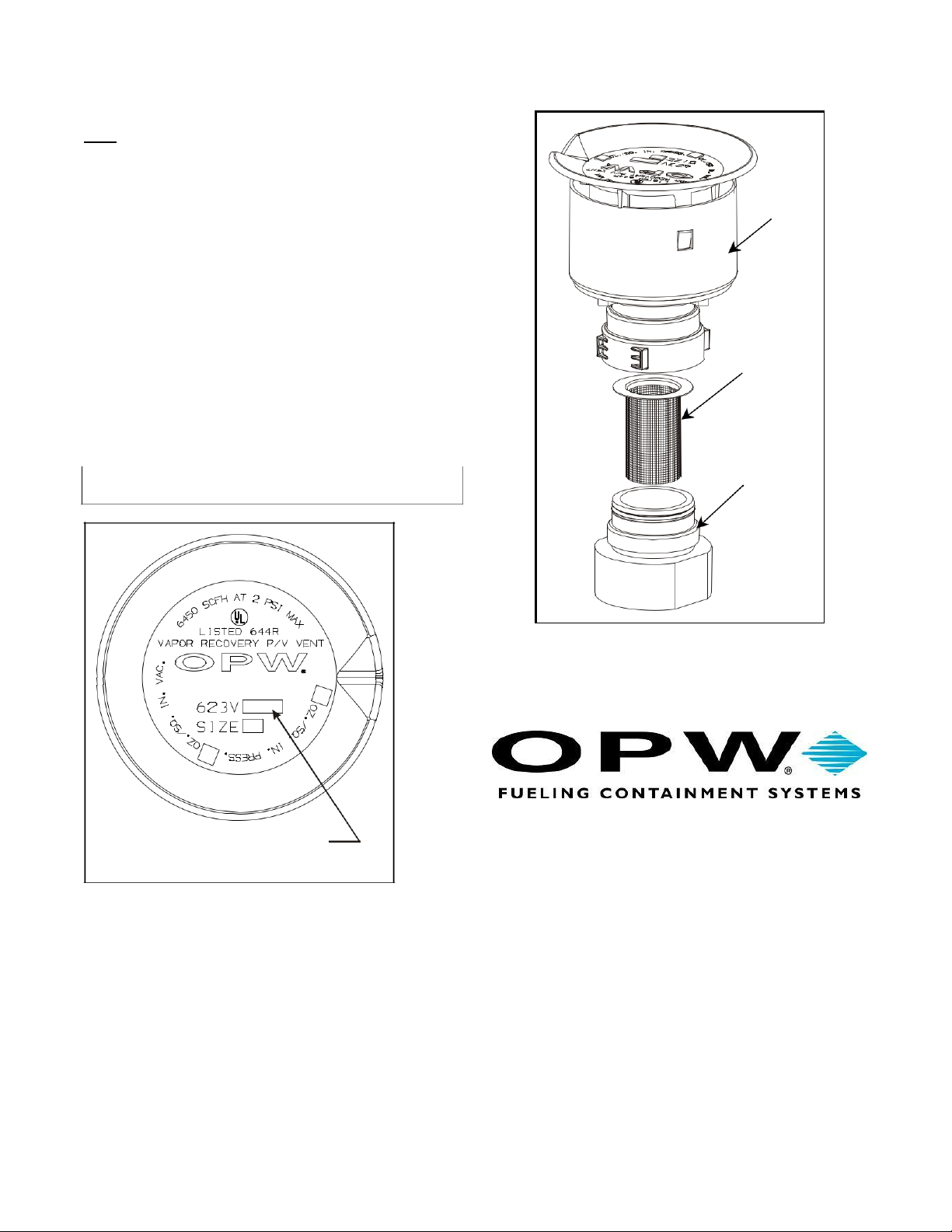
Especificaciones de Rendimiento
de la Serie 623V
Esta V lvula de Venteo/Presión Vacío ha sido
manufacturada y evaluada para las siguientes
especificaciones: Tasa de Fugas de Presión no debe
exceder 0.05 CFH a 2” W.C. Tasa de Fuga de Vacío
no debe exceder 0.21 CFH a -4” W.C. La presión de
disparo debe ser de 2.5” a 6” W.C. y el vacío de
disparo debe ser de -6 a -10” W.C. Evaluada usando
el Procedimiento de Prueba CARB TP-201.1E o la
Orden Ejecutiva de Primera Fase apropiada.
Especificación del Torque
Ensamblaje de la V lvula 2” NPT, 35 pies-libras
mínimo a 55 pies-libras m ximo.
Válvula de Venteo o Presión Vacío OPW 623V
INSTRUCCIONES DE INSTALACIÓN
Paso 1.
Desbarba y limpia la tubería de la v lvula a fondo.
Aplica lubricante de tubería a las roscas de la tubería
de la v lvula. El lubricante debe ser un compuesto de
sellado de roscas de tubería, resistente a la gasolina,
sin endurecimiento.
Paso 2 (Ver Figura 1)
Atornille el ensamblaje de v lvula sobre la tubería y tuerce
a un mínimo de 35 pies-libras a un m ximo de 55 pies-
libras. Solamente use las ranuras en el adaptador de la
tubería, No usar llave inglesa en ensamblaje de válvula
integrado.
NOTA NUNCA PINTE O CUBRA LA VÁLVULA
Ensamblaje de
la V lvula
Lubricante
De Tubería
Vent Pipe
Figura 1
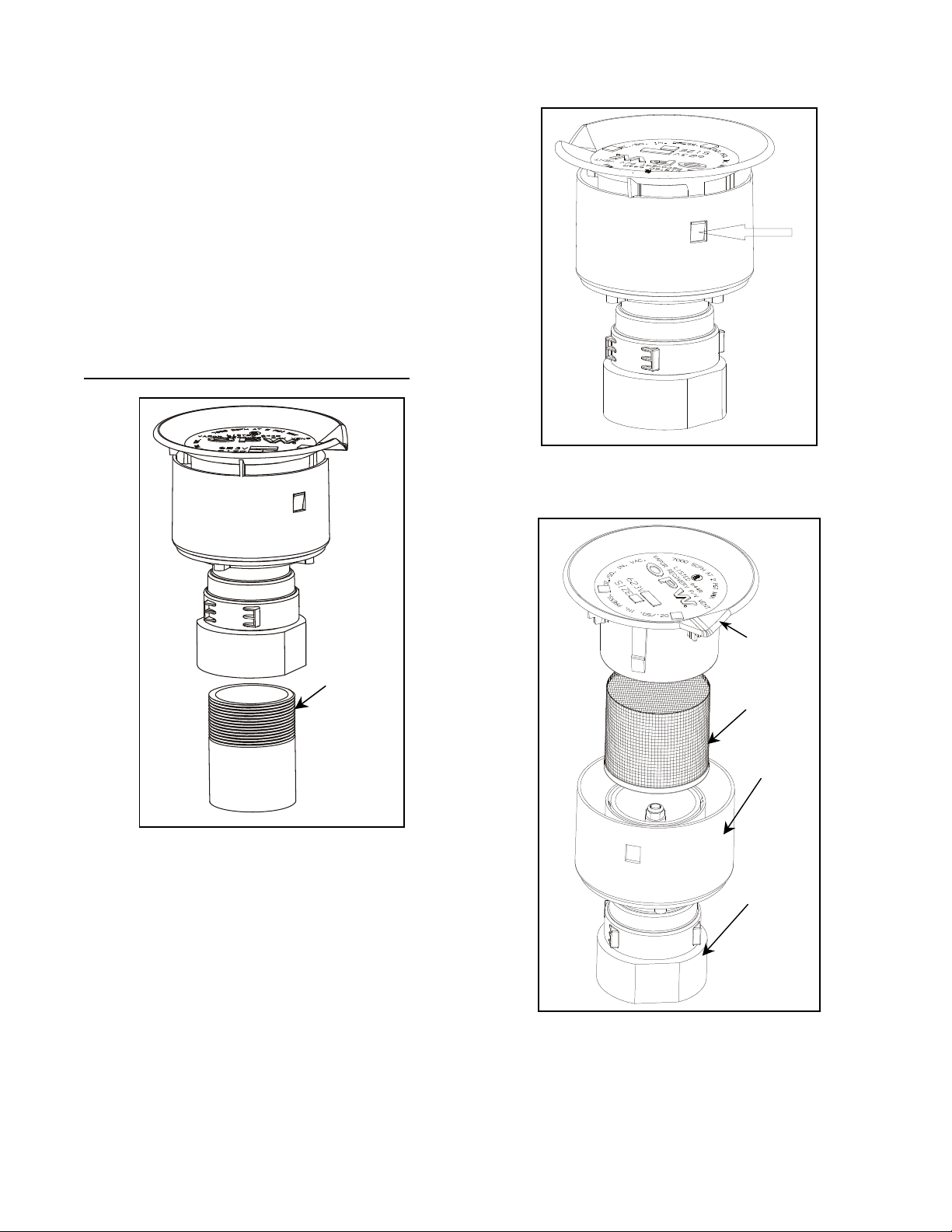
Funcionamiento y Mantenimiento
Se requiere un mantenimiento anual para mantener la
v lvula en funcionamiento. Quite e inspeccione mallas
de filtro – limpie o remplace como sea necesario.
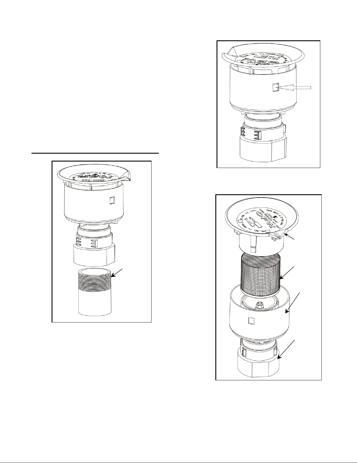
Mantenimiento de la Malla Superior
1. Remueve la cabeza de la v lvula al presionar las
pestañas como se indica en la Fig. 2, y levante la tapa
hacía arriba. La malla se deslizar hacia arriba y fuera
de la v lvula.
2. Limpie y cambie la malla de filtro (P/N H14895M)
como sea necesario y reinstale Fig. 3.
3. Reinstale la cabeza de la v lvula al reinsertarla dentro
del cuerpo. Asegure que las pestañas est n dentro del
cuerpo de la v lvula, y luego gire la cabeza hasta que
las pestañas encajen en su posición.
PRESIONAR
Figura 2
Cabeza de
la V lvula
Malla
Superior
Cuerpo
de la
V lvula
Adaptador
de Tubería
Figura 3
Mantenimiento de la Malla Inferior
Nota: No remueva el adaptador de la tubería de la
tubería de la v lvula para asistir la malla de filtro
inferior.
1. Remueve el ensamblaje de v lvula del
adaptador de tubería. Sujeta el ensamblaje en
las ranuras justo arriba del adaptador de tubería
y desatornilla. (Fig. 4) La llave C05102M puede
ser usada para este propósito.
2. Levante la malla de filtro y limpie o remplace
(P/N C05086M) como sea necesario.
3. Reinstale la malla de filtro en el adaptador de
tubería (ver Fig. 4 para guía).
4. Reinstale el ensamblaje de v lvula en el
adaptador de tubería y apriete hasta que se
detenga. No tuerza el ensamblaje de v lvula
a excepción de con P/N C05102M
Importante Deje estas instrucciones con el
Operador de Estación.
Fecha de Manufacturación
“MM / YY” MM = Mes, YY =
Año
Identificación del Producto
Cuerpo de
La V lvula
Malla
Inferior
Adaptador
De Tubería
Figura 4
3250 US Highway 70 Business W. Smithfield,
North Carolina 27577 Customer Service: 1-800-
422-2525
www.opwglobal.com
Copyright, 2006 - OPW Fueling Containment Systems, Smithfield, North Carolina
Printed in U.S.A. p/n H14898PA –Revised 7-20-2010
V lvula de Venteo o Presión a Vacío OPW 623V. p gina. 3

OPW 623V Pressure / Vacuum Vent Page 1
OPW Installation and Maintenance Instructions
OPW 623V Pressure / Vacuum Vent Valve
IMPORTANT: Please read these warnings and use
the assembly instructions completely and carefully
before starting. Failure to do so may cause product
failure, or result in environmental contamination due
to liquid leakage into the soil, creating hazardous
spill conditions.
IMPORTANT: The OPW 623V Pressure / Vacuum
vent is pre-assembled for your convenience and
ease of installation. Check to make sure the unit is
intact and undamaged and all parts have been
supplied. Never substitute parts for those supplied.
Doing so may cause product failure.
WARNING-DANGER: Using electrically operated
equipment near gasoline or gasoline vapors may
result in a fire or explosion, causing personal injury
and property damage. Be sure that the working area
is free from such hazards, and always use proper
precautions.
NOTE: At all times when product is in the storage
tank keep the vent pipe capped, so the vapors
cannot escape into the environment.
Notice: OPW products must be used in compliance
with applicable federal, state, and local laws and
regulations. Product selection should be based on
physical specifications and limitations and
compatibility with the environment and material to be
handled. All illustrations and specifications in this
literature are based on the latest production
information available at the time of publication.
Prices, materials, and specification are subject to
change at any time, and models may be
discontinued at any time, in either case, without
notice or obligation.
Standard Product Warranty
OPW warrants that products sold by it are free from
defects in materials and workmanship for a period of
one year from the date of manufacture by OPW
(ECO products two years from date of manufacture.)
Proof of purchase may be required. As the
exclusive remedy under this limited warranty, OPW,
will at its sole discretion, repair, replace, or issue
credit for future orders for any product that may
prove defective within the one year date of
manufacture period (repairs, replacements, or
credits may be subject to prorated warranty for
remainder of the original warranty period, complete
proper warranty claim documentation required.)
This warranty shall not apply to any product that has
been altered in any way, which has been repaired by
any party other than a service representative
authorized by OPW, or when failure is due to
misuse, or improper installation or maintenance.
OPW shall have no liability whatsoever for special,
incidental or consequential damages to any party,
and shall have no liability for the cost of labor,
freight, excavation, clean up, downtime, removal,
reinstallation, loss of profit, or any other cost or
charges.
For any product certified to California 2001
standards, OPW warrants that product sold by it are
free from defects in material and workmanship for a
period of one year from date of manufacture or one
year from date of registration of installation not to
exceed 15 months from date of manufacture by
OPW.
THIS WARRANTY IS IN LIEU OF ALL OTHER
WARRANTIES, EXPRESS OR IMPLIED, AND
SPECIFICALLY THE WARRANTIES OF
MERCHANTABILITY AND FITNESS FOR A
PARTICULAR PURPOSE. THERE ARE NO
WARRANTIES, WHICH EXTEND BEYOND THE
DESCRIPTION ON THE FACE HEREOF.
623V Series Performance
Specifications:
This Pressure / Vacuum vent has been
manufactured and tested to the following
specifications: Pressure leak rate not to exceed
0.05 CFH at 2” W.C. Vacuum leak rate not to
exceed 0.21 CFH at -4” W.C. The cracking pressure
to be 2.5” to 6” W.C. and cracking vacuum to be -6
to -10” W.C. Tested using CARB Test Procedure
TP-201.1E or applicable Phase I Executive Order.
Torque Specification:
Vent Assembly 2” NPT, 35 ft-lbs minimum to 55 ft-
lbs maximum.
OPW 623V Pressure / Vacuum Vent Page 2
OPW 623V Pressure / Vacuum Vent Valve
INSTALLATION INSTRUCTIONS:
Step1.
Deburr and thoroughly clean vent pipe. Apply pipe
dope to vent pipe threads. Pipe dope to be a non-
hardening, gasoline resistant pipe thread seal
compound.
Step 2: (See Figure 1)
Screw the vent assembly onto the vent pipe and
torque to 35 ft.-lbs minimum to 55 ft-lbs maximum.
Use the flats on the pipe adaptor only, Do not wrench
on the composite valve assembly.
NOTE: NEVER PAINT OR COVER THE VENT
Vent Pipe
Pipe Dope
Vent
Assembly
Operation and Maintenance:
Annual maintenance is required to keep the vent
operating satisfactorily. Remove and inspect filter
screens – clean or replace as necessary.
Upper Screen Maintenance
1. Remove vent top by depressing tabs as indicated
in Fig. 2, and lift top upward. Screen will slip up
and out of valve.
2. Clean or replace filter screen (P/N H14895M) as
necessary and reinstall Fig. 3.
3. Reinstall vent top by reinserting into the body. Be
sure the tabs are inside the valve body, and then
rotate top until the tabs snap into place
PUSH
Vent Top
Upper
Screen
Pipe
A
da
p
tor
Valve
Bod
y
Figure 1
Figure 3
Figure 2

OPW 623V Pressure / Vacuum Vent Page 3
Lower Screen Maintenance
Note: Do not remove the pipe adaptor from the vent
pipe to service the lower filter screen.
1. Remove valve assembly from the pipe adaptor.
Grip assembly at the flats just above the pipe
adaptor and unscrew. (Fig. 4) Wrench C05102M
can be used for this purpose.
2. Lift the filter screen out and clean or replace (P/N
C05086M) as necessary.
3. Reinstall filter screen in the pipe adaptor (see Fig.
4 for orientation).
4. Reinstall valve assembly on pipe adaptor and
tighten until it stops. Do not wrench valve
assembly except with P/N C05102M
Important: Leave these instructions with Station
Operator.
Manufacture Date “MM / YY”
MM = Month, YY = Year
Product Identification
Valve
Body
Lower
Screen
Pipe
A
daptor
3250 US Highway 70 Business W.
Smithfield, North Carolina 27577
Customer Service: 1-800-422-2525
www.opwglobal.com
Copyright, 2006 - OPW Fueling Containment Systems, Smithfield, North Carolina
Printed in U.S.A. p/n H14898PA –Revised 7-20-2010
Figure 4
Table of contents
Languages:
Other OPW Control Unit manuals


Popular Control Unit manuals by other brands

Festo
Festo Compact Performance CP-FB6-E Brief description

Elo TouchSystems
Elo TouchSystems DMS-SA19P-EXTME Quick installation guide

JS Automation
JS Automation MPC3034A user manual

JAUDT
JAUDT SW GII 6406 Series Translation of the original operating instructions

Spektrum
Spektrum Air Module System manual

BOC Edwards
BOC Edwards Q Series instruction manual

KHADAS
KHADAS BT Magic quick start

Etherma
Etherma eNEXHO-IL Assembly and operating instructions

PMFoundations
PMFoundations Attenuverter Assembly guide

GEA
GEA VARIVENT Operating instruction

Walther Systemtechnik
Walther Systemtechnik VMS-05 Assembly instructions

Altronix
Altronix LINQ8PD Installation and programming manual


