Orbis Viaris Uni User manual

1
VIARIS UNI
EV SMART CHARGER

2
INDEX
DESCRIPTION ......................................................................................... 3
SMART CHARGER INSTALLATION........................................................ 5
LUMINOUS INDICATORS...................................................................... 16
EV CHARGER STATES......................................................................... 18
CHARGING PROCESS.......................................................................... 21
CONTROL OF THE SMART CHARGER VIA WEB ............................... 22
VIARIS APP FOR MANAGEMENT FROM SMARTPHONE ................. 23
MAINTENANCE...................................................................................... 26
TECHNICAL CHARACTERISTICS ........................................................ 27
EXTERNAL DIMENSIONS..................................................................... 27
REPLACE THE BATTERY ..................................................................... 28
EXTRAS ................................................................................................. 29
TROUBLESHOOTING............................................................................ 29
DIRECTIVES AND REFERENCE STANDARDS ................................... 31

3
DESCRIPTION
VIARIS UNI smart chargers have a set of embedded elements that are required
to connect the electric vehicle (EV) to the electrical supply in order to recharge.
The VIARIS UNI has been designed with a robust IK10 casing, which requires
easy wall mounting and is extremely easy to use.
The operating status of the charger is always visible through its indicator lights.
The VIARIS UNI includes a load modulator that allows the user to adjust the
power of the equipment according to the contract in the electrical installation.
This modulator allows the VIARIS UNI to regulate the power supplied to the
electric vehicle depending on the total consumption of the installation. This
prevents unnecessary over-costs and reduces the risk of over-currents in the
network.
VIARIS UNI chargers perform the charging of electric vehicles via a connection
cable (hose) with Type 2 connector, and with charging modes 3 (load modes
are specified in EN 61851-1).
Optionally the VIARIS UNI can have an additional Schuko intake (load modes 1
and 2) limited to 14 A.
The Schuko is not controlled with the modulator but can be connected and
disconnected by the App or the web, and the App shows the current it
consumes and its state. If you exceed 14 A for 5 seconds you disconnect, and
to connect it we must use the App or the embedded web.
It has a series of optional accessories that complement the functionality of the
equipment, in addition to the VIARIS app for mobile, available on Google Play
and App Store for free.

4
Warning symbols used in this instruction manual:
ELECTRICAL HAZARD. There is a risk of electrocution that
can cause bodily injury or death if instructions are not followed
GENERAL ATTENTION
Description of elements
Cable de
conexión
Indicadores
luminosos
Área de activación
Táctil o por RFID
Entrada de
acometida
Base de
instalación
Marco
Frame
Electrical
connection
in
p
ut
Wall
mounting
p
late
Luminous
indicators
Connection
hose
Touch or RFID
activation area

5
SMART CHARGER INSTALLATION
Safety warnings
During the installation and operation of the charger, it is necessary to observe the
following instructions:
Equipment must be installed by authorized and qualified personnel who
strictly comply with the instructions of this manual.
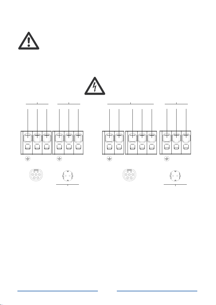
Equipment must be installed and activated in compliance with the current
low voltage regulation.
Do not use the equipment for other purposes than specified.
Before installing the smart charger, check that it is not damaged.
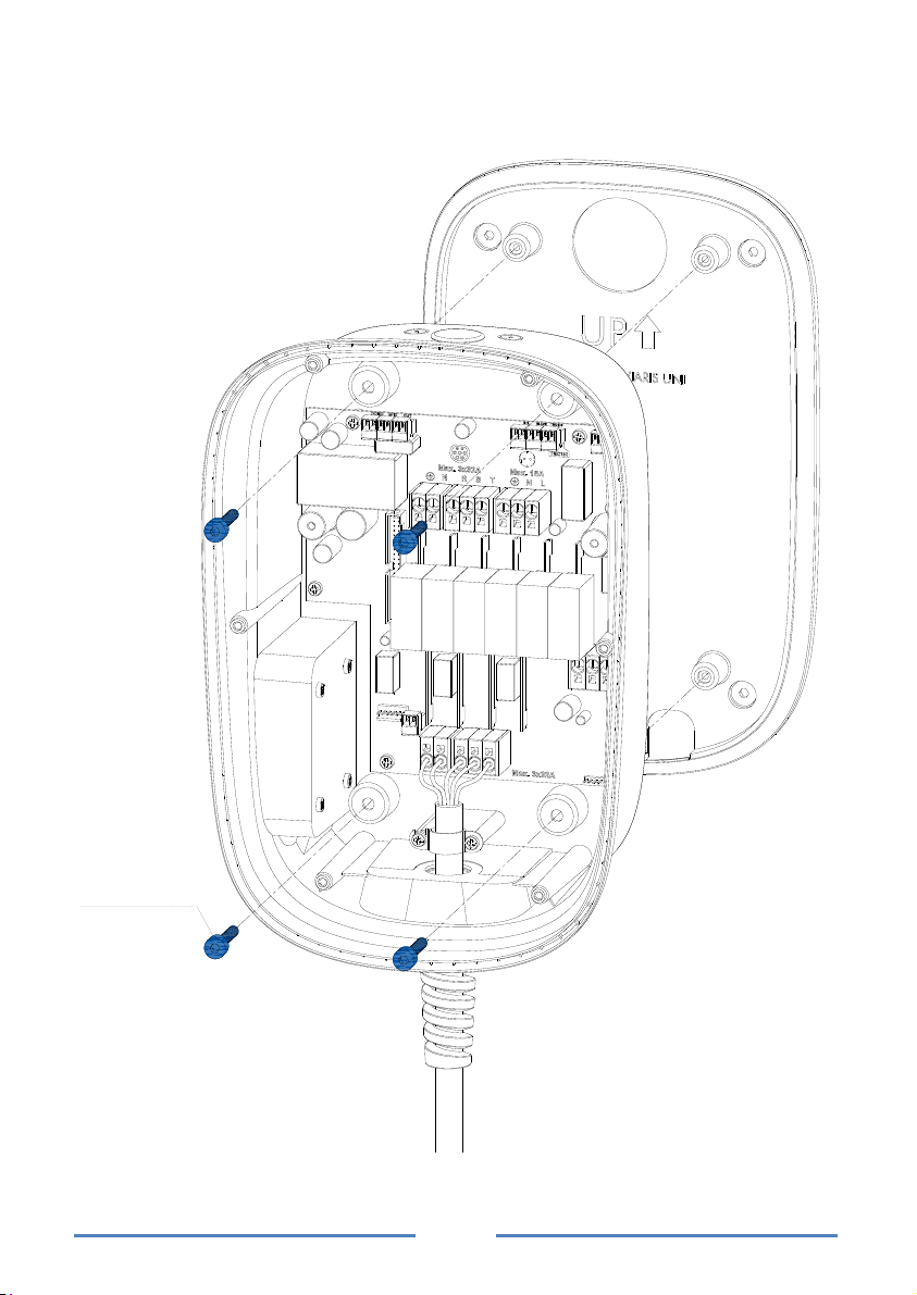
Before accessing the connection terminals, check that the cables are not
under electric voltage. The opening of the enclosure does not imply the
absence of voltage in its interior. Only authorized and qualified personnel
can open it.
In accordance with the applicable regulations, installation personnel
should check if overvoltage protection measures are necessary.
Use only the charging cable specified for each electric vehicle. Under no
circumstances should another type of extension cable be used.
In case of malfunction, do not make repairs and immediately contact our
Technical Service.
After installation, connection terminals must not be accessed without
proper tools.
To protect the smart charger against possible vehicle impacts, it is
recommended to install a protective barrier.
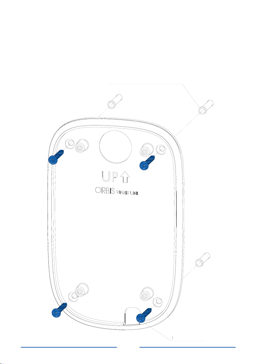
Indications on assembly
The minimum installation height of the outlets and connection hoses
will be 0.6 m above ground level. If the charger is intended for public
use, the maximum height will be 1.2 m. In places for people with
reduced mobility, it will be between 0.7 m and 1.2 m. (Check the
specific instructions of the country where the installation is performed
in case other heights are specified).
The connection hose support must be located between 0.4 m and 1.5
m above ground level.
Indoor use only.
The charger must be installed in an upright position and without any
surrounding obstacles to allow its maintenance.
Use joints or cable glands to ensure the IP protection rating of the
charger.

6
Wall mounting
Remove the wall mounting plate.
In order to fix the charger to the wall, four holes for Ø10 mm screw anchors
(supplied) must be made, using the wall mounting plate as a template.
Then, the wall mounting plate will be screwed in.
tornillos de
Ø10 mm (x4)
taladros pared con taco
para tornillos de Ø10 mm (x4)
Ø10 mm screw anchors wall
holes (x4)
Ø10 mm
screws (x4)

7
Once the wall mounting plate is fixed, place the charger on and screw it with the
four M6 screws supplied.
tornillos M6 (x4)
M6 screws (x4)

8
Power connection of the equipment
Before accessing the connecting terminals, verify that the cables are
not under electric voltage. The opening of the envelope does not
imply the absence of tension within it. It may only be opened by
authorized and qualified personnel.
Once mounted on the wall, perform electrical connections according to the
following connection scheme:
230 V~
Max. 16A
NL
NL
230 V~
Max. 32A
OPCIONAL
Max. 3x32A
N
Max. 16A
NL
L3
OPCIONAL
230 V~
3x230 V~
L2 L1
The terminals marked as Optional are to connect the supply of the additional
Schuko output on the equipment have. This connection should be protected
with independent protections to the main intake.
If your VIARIS UNI does not have as option the additional Schuko output these
terminals are not functional, avoid making a connection in them.
SINGLE PHASE THREE-PHASE
OPTIONAL OPTIONAL

9
Connection of the load modulator
Open the TMC100 transformer (included) and couple/clamp it on the phase
conductor (L) so that it measures the total consumption of the house and the
charger VIARIS UNI.
RESPECT THE SENSE OF CURRENT INDICATED ON THE TMC100 LABEL.
It should not be used in installations with currents exceeding 100 A,
the measurement and therefore modulation may be incorrect.
Single phase connection Three-phase connection
Connect the output of the TMC100 to the plug-in terminal block connector
supplied and connect to the VIARIS UNI control circuit.
Must be used twisted pair cable with section 0.25-0.5 mm², maximum
length 1000 m, with a
peeling of 6-7 mm, and torque of 0.2 Nm.
L
I máx 100 A
HOUSEHOLD
METER
HOUSEHOLD +
CHARGER
I máx 100 A
HOUSEHOLD
METER
HOUSEHOLD +
CHARGER
VIARI UNI
CIRCUIT
TMC100-
TMC100+
TMC100-
TMC100+
+-
1
23
L1L2
L3
+
-
L
+-+-

10
Respect the indications in the image so that the measurement is correct.
Configuration according to the power contracted
To configure the rated power of the installation, use the rotating knob on the
rear face of the front, or programming by App or embedded web. For app or
web programming to take effect, the rotating knob must be in the “NO LIMIT.”
position.
The position of the rotating knob defines the maximum current of the
installation; this parameter must be configured according to the rated power in
the installation as shown in the following table.
This adjustment is fundamental for the correct operation of the load modulator.

11
If the TMC100 transformer is not installed, the position of the rotating knob must
be in the “NO LIMIT” position in order not to limit the load current.
Current
Single
phase
power
Three-
phase
power
NO LIMIT. NO LIMIT. NO LIMIT.
10 A 2,3 kW 6,928 kW
13 A 3 kW 9 kW
15 A 3,45 kW 10,392 kW
18 A 4,14 kW 12,42 kW
20 A 4,6 kW 13,856 kW
23 A 5,3 kW 15,9 kW
25 A 5,75 kW 17,321 kW
28 A 6,44 kW 19,32 kW
30 A 6,9 kW 20,785 kW
35 A 8,05 kW 24,249 kW
40 A 9,2 kW 27,713 kW
45 A 10,35 kW 31,177 kW
50 A 11,5 kW 34,641 kW
55 A 12,65 kW 37,95 kW
63 A 14,49 kW 43,648 kW

12
External activation connection
There is the possibility to activate the charger using an external signal (e.g.
from a home automation system or from a prepaid system). This signal is
priority over any other load activation system; therefore if the external activation
is activated, charging would start when the vehicle is connected to the charger.
The connection must be done by plugging the inputs of the DOMO connector
with an external circuit free of potential.

13
External extractor connection
Some electric vehicles may require for optimal working of their loading system
that the environment where the charger is installed has natural or forced
ventilation. In the case of closed garages, the heat generated by the vehicle
must be evacuated by means of an air extraction system external to the
charger.
The VIARIS UNI has a potential-free output of 220 Vac and 5 A of maximum
consumption marked OUT, which will activate an air extraction system when
the vehicle demands it.

14
Front connection
When we have all the connections made, we connect the flat cable in the
connector of the front as shown in the image, making sure it is firmly connected
by the side tabs of the connector.
If you need to remove the front in the future, be careful to disconnect the cable
by pressing the side tabs on the connector.

15
Closed of the charger
We cover the charger with its front and screw it with its screws.
To finish the installation we place the frame and give tension to the equipment.
tornillos Ø4,2 mm (x6)
Ø4.2 mm screws (x6)

16
LUMINOUS INDICATORS
A
ctivation
zone
“Attention”
indicator
Wi-Fi
indicator
Connection
cable
indicator
Modulator
indicator
Status bar

17
Connection cable indicators
Off: free connector, unlocked and available.
Green blinking: ready for insertion.
Fixed green: connection cable connector inserted in vehicle and
waiting confirmation of vehicle loading.
Fixed white: in the process of loading.
Other indicators
Wi-Fi indicator
White blinking: establishing connection with web server.
Fixed white: connected to the web server.
Blinking blue: local connection to PC or mobile phone.
Off: no Wi-Fi connection.
Charge modulator indicator
Fixed: modulation working.

18
EV CHARGER STATES
By changing illumination color in the status bar, the charger indicates us its
different modes of operation:
Rest mode
Charger available. No connected vehicle and without loading permission.
Status bar illumination in fixed green.
Connection cable indicator off.
Connected mode without loading permission
Vehicle connected to the charger and ready to load. Without loading permission.
Status bar illuminate in green from outside towards the center.
Fixed green connection cable indicator.
Free mode with loading permission
No vehicle connected. With charge permission enabled.
Status bar illumination in fixed green.
Connecting cable indicator in green blinking.

19
Mode ready to load
Charger connected to the vehicle.
Status bar illumination in fixed blue.
Fixed green connection cable indicator.
Load mode
Charger connected to the vehicle and charging.
Status bar illuminate blue with varying intensity.
Fixed white connection cable indicator.
End mode loading
Vehicle connected to the charger with the finished charge.
Status bar illumination in blinking blue.
Fixed green connection cable indicator.

20
Reserved mode
When a charger reservation is made through the management platform.
Status bar illumination in fixed white.
Mode Updating
When a charger update is in progress.
Status bar illuminate in white from outside towards the center.
Error mode
When a charger malfunction occurs.
Status bar illuminate red with varying intensity.
“Attention” indicator in fixed red.
Other manuals for Viaris Uni
1
Table of contents
Other Orbis Batteries Charger manuals