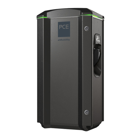
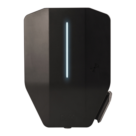
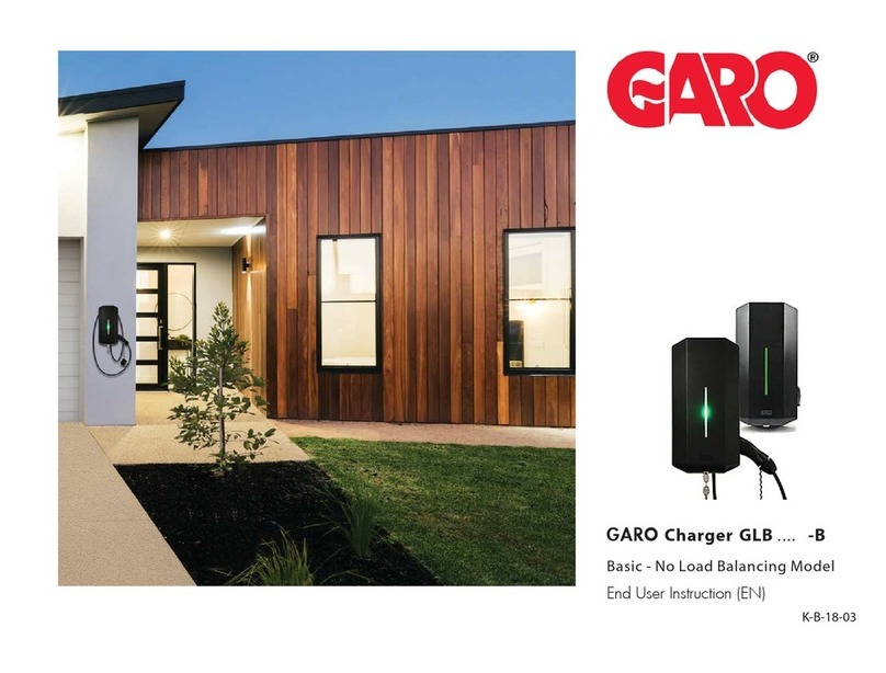
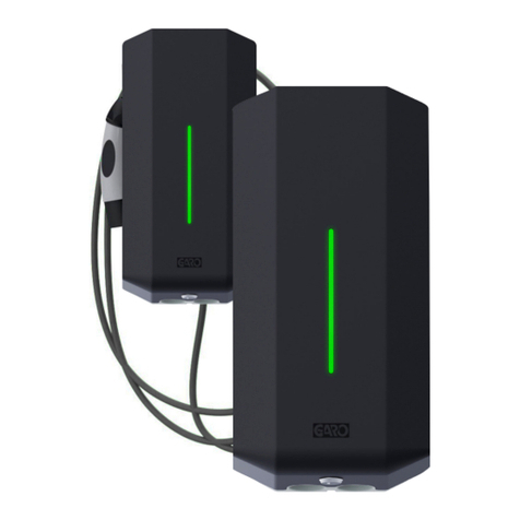
GARO Castra CLS1 User manual

GARO AB
GARO Castra
Box 203, SE–335 25 Gnosjö
Phone: +46 (0) 370 33 28 00
garo.se
Manual 380238
Installation manual

INFORMATION 3
Warnings 3
Note 3
INSTALLATION 4
INSTALLATION OF ACCESSORIES 4
USER INSTRUCTIONS 4
Technical date 5
Software update 5
Service / Maintenance 5
Troubleshooting / Support 5
GARANTIVILLKOR / WARRANTY CONDITIONS 11
WARRANTY FORM / GARANTIFORMULÄR 12
2
EN

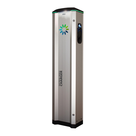
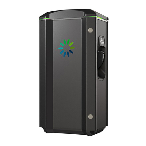
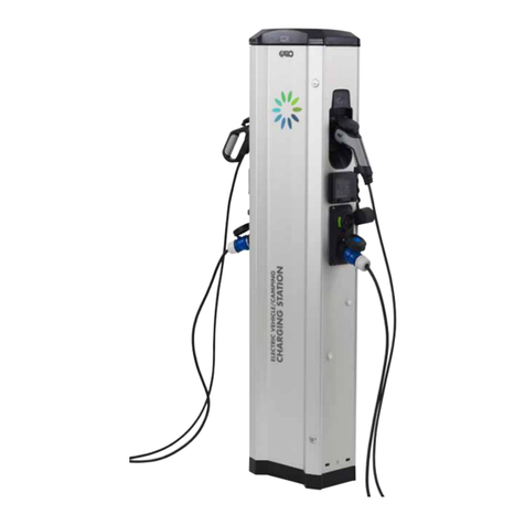
Castra campingstation is a combined socket outlet and EVSE
charging station. Each station contain two electric outlets and two
type 2 EV outlets.
To add more comfort, each Castra is prepared to supply drinking
water. Water taps are available as accessory.
IP44 and IK10 housing means that Castra can handle the rough
environment a public equiment is exposed to.
Castra is equipped with dual pole incoming terminal block, and
it mean that power cables are easy to daisy-chain with another
Castra campingstation.
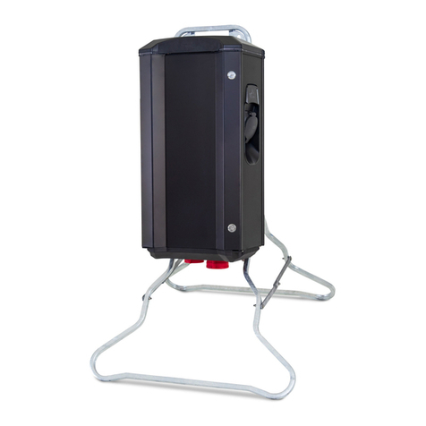
With a separate assembing kit, two Castra can install together
”back to back”. You will in this way have electrical and drinking
water supply for four separate equipage.
3
EN
Castra campingstation contains:
2x 216-6 outles
2s Type 2 EV outlets
Castra left hand side outlets are connected to L1 and right
hand side outlets are connected to L2. Each side can
consume max 10A alt 16A depending on model.
The 216-6 outlet and the EV outlet at same side share
same phase.
When less than 6A available current, the EV outlet will
paus the charging process to prevent overload.
216-6 outlets should use for caravans/tents etc.
EV outlets should use for electric vehicle.
Each side have individual energy meter that register the
total consumption (kWh) for each side of Castra.
Both 216-6 and EV outlets are individually protected to
RCBO:s.
Both EV outlets have individual DC-fault monitoring
devices.
Castra campingstation are delivered with RFID-readers
on both sides. By logging in to Castra webinterface with
a mobile/tablet/computer, RFID authorization can be
activated for the EV outlets. The registration of RFID-tags
RFID and settings are also handled in the webinterface. At
delivery, the functions is deactivated.
Note
INFORMATION
Warnings
Electrical installation is only allowed by professional
electrician and must follow local country regulation. If any
questions, contact your local electrical authority.
Dielectric Voltage Withstand Test is not allowed on Castra
campingstation.
Castra campingstation must be grounded according to
local country regulation.
Castra campingstations Type 2 outlets as designed
exclusively for charging electric vehicles.
Ventilation signal from EV is not supported.
Adapters for charging connectors are not allowed to be
used.
Cord extension sets for charging cable is not allowed to
be used.
Do not use private power generators as a power source
for Castra. Fluctuating voltage can har both an EV:s
battery and the EV:s internal electronics.
Do not operate Castra in temperatures outside its
operating range – see technical specifications.
Warranty is not valid if Castra’s hardware or software is
modified by a non authorized person.
INSTALLATION OF ACCESSORIES
Two Castra campingstations can be installed “back to back” pic 6.
(use GARO art no 353918)
Water taps installation, pic 7 (GARO art no 352711)
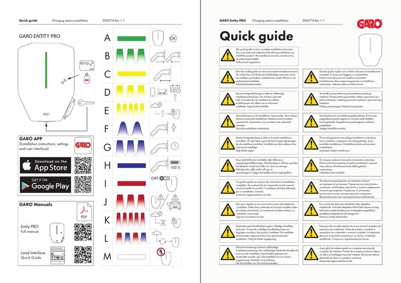
Basic LED indications
Solid green light: ready for charging
Flashing green light: Castra waiting for start
signal from electric vehicle.
Shifting blue light intensity: charging
Other LED indicatoions: see User manual at
www.garoemobility.com/support
Error codes:
Fixed yellow light: reconnect the charging cable.
Fixed white light: EV outlets not activated, contact
serviceperson.
No light: Contact service person
Fixed red light: Reset RCBO
Slow red blink: Modbus problem with energymeters,
contact service person
Red blink: RFID tag not valid
4
EN
USER INSTRUCTIONS
Connect the charging cable to the EV outlet.
If RFID authorization is activated, hold a valid RFID-tag in front of
the RFID-reader at same side as the charging cable in use.
The charging process is activated if the EV is ready for charging.
See your EV manual.
When charging is complete, follow the instruction in your EV
manual.
INSTALLATION
1. Open the front door and remove the protection cover.
2. Cut a round hole in the gasket for the incoming cable. Make
sure the gasket fits tight around the cable to prevent dirt, dust and
bugs to enter the top housing part.
3. Install Castra on a pole dia 60mm or on a ground foundation
pic2. Pole or ground foundation is not included.
4. Install the incoming cable, pic 3 and 4.
Note: 3-wire system, add a jumper between L1 and L2 on the
terminal block.
When several Castra campingstations are connected to same
distribution board, phase-rotation is recommended to even out the
load between the phases.
Example:
1st Castra: L1, L2, L3
2nd Castra: L3, L1, L3
3rd Castra: L2, L3, L1
And so on…
5. Fix the protection cover.
6. Turn on the power and wait a few minutes for Castra to start up
properly.
7. Test Castra both side outlets with a test instrument.
8. Fill in the warranty form, sign with name, date and company
name in order for the warranty to be valid. Give the signed
warranty form to the owner of the site.

Technical date
Specifications
Product type: All Castra CLS1 modeller
Standards: IEC 61851-1 and IEC TS 61439-7
Installation: Ground/Pole
Rated Voltage: 230V/400V 50Hz
Installation systems: TT-, TN- och IT-systems
Charging Type: Mode 3
Protection Class: IP44
Mechanical Impact Resistans: IK10
Temperature Range: -250C – +400C
Storage temperature: -350C – +550C
Weight: 22,5 - 24,5 kg depending on model
EMC Classification: 2014/30/EU
Installation environment: Indoor / Outdoor
Location type: Non-restricted Access
Charging method AC Charging
Rated current withstand 10kA
Rated short-time withstand current 10kA
Rated conditional short-circuit current of an assembly 10kA
Short-circuit protective device type Type C
Rated impulse withstand voltage 4kV
Rated insulation voltage 230/400V
Rated current of each circuit 10-16A depending on model
Rated diversity factor RDF=1
Pollution degree: 3
EMC environmental condition A and B
5
EN
Software update
Service / Maintenance
Troubleshooting / Support
See user manual on www.garoemobility.se/support
See user manual on www.garoemobility.com/support

476±10 mm
1 2
pole
2
ground
Option:
Art no 352699, E2449896
6
EN

34
5
a
b
Option:
Art no 352699, E2449896
7
EN

Option: Art no 352711, E2449844
Option: Art no 353918
ø 40,5 mm
+/- 0,5
x8
x4
x4
x4
8
EN

L3
L2
L1
N
PE
-X1
1
2
3
4
A1
A2
-QA1
1
2
3
4
A1
A2
-QA2
CT2
CT1
CP
PP
L1
L2
L3
PE
N
-XD2
CP
PP
L1
L2
L3
PE
N
-XD1
CT1
CT2
-XPE1-XN1
PP 2
CP 2
Red
White
PP 1
CP 1
Red
White
LINE (L)
FC2
FC1
XN1
XPE1
QA1
QA2
A-
B+
XPE1
XN1
HÖGER SIDA
VÄNSTER SIDA
NN
1 2
B+
A-
6785
-P2
RS-485
NN
1 2
B+
A-
6785
-P1
RS-485
N 2
-FC2
C10A
N 1
mA30
N 2
-FC1
C10A
N 1
mA30
N 2
-FC3
C10A
N 1
mA30
N 2
-FC4
C10A
N 1
mA30
N
PE
L
N
PE
L
A-
B+
-P1
-P2
ISOLERAS!
ISOLERAS!
HB
1 3 5
642
9
EN

3
4
TWIN 1fas MÄTARE CAMPING
art.nr.
GARO AB
Tel: 0370-33 28 00
335 33 Gnosjö
SWEDEN
Södergatan 26
info@garo.se
ARBETSNUMMER DATUM
2020-12-03
KONSTRUERAD AV
SENASTE ÄNDRING
RITAD AV
JAN G
BLAD
NÄSTA BLAD
UTGÅVA
-1
Fuse/RccB FB
Contactor FB
Contactor control
Line (L)
Neutral (N)
Protective earth (PE)
A-
B+
Remote control
A-
B+
ON
SW2
123456
ON
SW1
E-Meter
Datalink
Fuse
1. blue/brown
2. blue/red
3. blue/yellow
4. blue/green
5. white
6. red
Connector for
OCPP/Wi-Fi module
Fuse/RccB FB
Contactor FB
Contactor control
Line (L)
Neutral (N)
Protective earth (PE)
A-
B+
Remote control
A-
B+
ON
SW2
123456
ON
SW1
E-Meter
Datalink
Fuse
1. blue/brown
2. blue/red
3. blue/yellow
4. blue/green
5. white
6. red
Connector for
OCPP/Wi-Fi module
CP 2
PP 2
CT2
CP 1
PP 1
CT1
FC1
FC2
XN1
XPE1
QA1
QA2
LINE (L)
A-
B+
-P2
communication cable
communication cable
-KF1
Connector for
Led light Topcard Connector for
the RFID reader
Connector for
Led light Topcard Connector for
the RFID reader
M
M
SW3SW3
SW3SW3
XPE1
XN1
ON
SW2
1234
=16A
UTTAG
ON
SW2
1234
=16A
KABEL
ON
SW1
123456
ON
SW2
1234
=32A
UTTAG
ON
SW2
1234
=32A
KABEL
FABRIKSINSTÄLLNING
FAST KABEL : ska svartvit (CP) in på plint 5
A-
B+
-P1
6=OFF
ALL=OFF
5=OFF
4=OFF
3
2
1
3=OFF
2=OFF
1=OFF
SW1 CC1
6
5
4
PROTECTING LABEL
ON OFF
6=ON
5=ON
4=ON
3
2
1
3=OFF
2=OFF
1=CASTRA MODEL:
ON=16A, OFF=10A
SW1 CC2
6
5
4
ON OFF
6=ON
5=ON
4=ON
3
2
1
3=OFF
2=OFF
1=CASTRA MODEL:
ON=16A, OFF=10A
SW1 CC2
6
5
4
ON OFF
OFF=OUTLET4=OFF
3
2
1
3=OFF
2=ON
1=OFF
SW2
4
OFF, ON, OFF=10A
ON OFF
OFF=OUTLET4=OFF
3
2
1
3=ON
2=OFF
1=OFF
SW2
4
OFF, OFF, ON=16A
ON OFF
OFF=OUTLET4=OFF
3
2
1
3=OFF
2=ON
1=OFF
SW2
4
OFF, ON, OFF=10A
ON OFF
OFF=OUTLET4=OFF
3
2
1
3=ON
2=OFF
1=OFF
SW2
4
OFF, OFF, ON=16A
CC1 CC2
SW3
Press 3s for network
factory reset
LEFT RIGHT
10
EN

1. The product benefits from manufacturer´s warranty. The applicable warranty period must be stated in purchase documents from
your supplier.
2. The product must be installed by a certified installer / contractor.
3. Proper installation, storage and operation conditions must be obtained.
4. Warranties apply only to products installed in their original installation location.
5. Installation, use, care, and maintenance must be normal and in accordance with instructions.
6. Warranty requires a dated, fully filled in Warranty form by an certified installer/contractor. If the original installation date cannot
be verified, then the warranty period begins ninety (90) days from the date of product manufacture (as indicated by the model and
serial number).
7. Warranty does not cover damage occured by incorrect use of equipment, use of any nonoriginal spareparts, lack of maintenence
or faults caused by disassembly of the product or unauthorized persons intervention.
8. Warranty does not cover software or update thereof.
9. Warranty does not cover aesthetic deficiencies caused by negligent manipulation or accidents (breaks or damage to the carcass).
10. Warranty does not cover damage caused by external overvoltage from either grid or car/charging object.
11. Warranty does not cover damage caused by force major like for example but not limited to: floods, winds, fires, lightning,
accidents, sabotage, military conflicts, terrorism, vulcanos, earthquakes or corrosive environments.
GARANTIVILLKOR / WARRANTY CONDITIONS
SVERIGE/SWEDEN
Garantivillkor enl ALEM 09.
OBS! Fullständigt ifylld garantiblankett krävs
Garantin gäller ej om produkten varit utsatt för ett isolationstest, sk meggning.
11
EN

WARRANTY FORM / GARANTIFORMULÄR
Model: M no:
ELECTRICAL INSTALLATION DATA
Group fuse (A)/Gruppsäkring (A)
Supply cable dimension/Kabelarea:
FUNCTION TEST
Testbox / EV (model)
Date/Datum:
Sign Installer/Sign installatör:
Company Name/Företagsnamn:
Owner / Customer Name/Ägare/Kundens
namn:
Installation adress:
12
EN
Table of contents
Other GARO Batteries Charger manuals

GARO
GARO LS4 43kW User manual

GARO
GARO Twinbox GTB Series User manual

GARO
GARO Wallbox GLB User manual

GARO
GARO GLB****-B series Installation instructions

GARO
GARO ENTITY PRO Owner's manual

GARO
GARO ENTITY PRO User manual

GARO
GARO Castra User manual

GARO
GARO Wallbox GLB Series User manual

GARO
GARO LS4 Wallmounted User manual