ORiNG IGMG-P83244GC+-D4G User manual
COPYRIGHT NOTICE
Copyright © 2018 ORing Industrial Networking Corp.
All rights reserved.
No part of this publication may be reproduced in any form without the prior written consent of
ORing Industrial Networking Corp.
I
IG
GM
MG
G-
-P
P8
83
32
24
44
4G
GC
C+
+-
-D
D4
4G
G
I
In
nd
du
us
st
tr
ri
ia
al
l
C
Ce
el
ll
lu
ul
la
ar
r
M
M2
2M
M
G
Ga
at
te
ew
wa
ay
y
U
Us
se
er
r
M
Ma
an
nu
ua
al
l
V
Ve
er
rs
si
io
on
n
1
1.
.0
0
M
Ma
ar
rc
ch
h,
,
2
20
01
19
9
w
ww
ww
w.
.o
or
ri
in
ng
gn
ne
et
t.
.c
co
om
m

IGMG-P83244GC+-D4G User Manual
ORing Industrial Networking Corp. 1
TRADEMARKS
is a registered trademark of ORing Industrial Networking Corp.
All other trademarks belong to their respective owners.
REGULATORY COMPLIANCE STATEMENT
Product(s) associated with this publication complies/comply with all applicable regulations.
Please refer to the Technical Specifications section for more details.
WARRANTY
ORing warrants that all ORing products are free from defects in material and workmanship for a
specified warranty period from the invoice date (5 years for most products). ORing will repair or
replace products found by ORing to be defective within this warranty period, with shipment
expenses apportioned by ORing and the distributor. This warranty does not cover product
modifications or repairs done by persons other than ORing-approved personnel, and this
warranty does not apply to ORing products that are misused, abused, improperly installed, or
damaged by accidents.
Please refer to the Technical Specifications section for the actual warranty period(s) of the
product(s) associated with this publication.
DISCLAIMER
Information in this publication is intended to be accurate. ORing shall not be responsible for its
use or infringements on third-parties as a result of its use. There may occasionally be
unintentional errors on this publication. ORing reserves the right to revise the contents of this
publication without notice.
CONTACT INFORMATION
ORing Industrial Networking Corp.
3F., No.542-2, JhongJheng Rd., Sindian District, New Taipei City 23148, Taiwan (R.O.C.)
Tel: +886-2-2218-1066 // Fax: +886-2-2218-1014
Website: www.oringnet.com
Technical Support
E-mail: support@oringnet.com
Sales Contact
sales@oring-networking.com.cn (China)

IGMG-P83244GC+-D4G User Manual
ORing Industrial Networking Corp. 2
Tables of Content
Getting Started.................................................................................................1
1.1 About the IGMG-P83244GC+-D4G ...................................................................................1
1.2 Software Features ................................................................................................................1
1.3 Hardware Features...............................................................................................................1
Hardware Overview.........................................................................................2
2.1 Bottom Panel.........................................................................................................................2
2.1.1 Ports and Connectors..........................................................................................................2
2.1.2 Front Panel LEDs ...............................................................................................................3
2.2 Top Panel...............................................................................................................................4
2.3 Rear Panel.............................................................................................................................4
Hardware Installation......................................................................................5
3.1 DIN-Rail Mounting................................................................................................................5
3.2 Wall Mounting........................................................................................................................5
3.3 Wiring .....................................................................................................................................7
ATTENTION.........................................................................................................................................7
3.3.1 Grounding..............................................................................................................................7
3.3.2 Fault Relay.............................................................................................................................7
3.3.3 Redundant Power Inputs.....................................................................................................7
3.4 SIM Card Installation............................................................................................................8
Cables and Antenna........................................................................................9
4.1 Ethernet Pin Definition.........................................................................................................9
4.2 Serial Port Pin Definition....................................................................................................10
4.3 Cellular Antenna..................................................................................................................11
Management ..................................................................................................12
5.1 Network Connection...........................................................................................................12
5.2 Configuration.......................................................................................................................13
5.2.1 Basic Setting.....................................................................................................................13
5.2.1.1 WAN...............................................................................................................................13
5.2.1.2 LAN ...............................................................................................................................17
5.2.1.3 DHCP.............................................................................................................................18
5.2.1.6 DDNS.............................................................................................................................21
5.2.1.7 Date & Time...................................................................................................................21
5.2.2 Serial Setting ....................................................................................................................22
5.2.3 Ignition Edge ....................................................................................................................32
5.2.4 Open Gateway-Inside .......................................................................................................33
5.2.5 Networking Setting...........................................................................................................33
5.2.2.1 NAT Setting....................................................................................................................33
Virtual Server.............................................................................................................................33

IGMG-P83244GC+-D4G User Manual
ORing Industrial Networking Corp. 3
5.2.2.2 Firewall Setting ..............................................................................................................35
5.2.2.3 VPN Setting ...................................................................................................................38
5.2.2.4 VRRP .............................................................................................................................46
5.2.2.5 Routing Protocol ............................................................................................................47
5.2.6 System Tools.....................................................................................................................50
5.2.3.1 Login Setting..................................................................................................................50
5.2.3.2 Router Restart.................................................................................................................51
5.2.3.3 Firmware Upgrade .........................................................................................................52
5.2.3.4 Save/Restore Configurations..........................................................................................52
5.2.3.5 Remote Management......................................................................................................53
5.2.3.6 Miscellaneous.................................................................................................................54
5.2.3.7 Port Setting.....................................................................................................................54
5.2.3.8 Event Warning................................................................................................................55
5.2.3.9 Disk................................................................................................................................59
5.2.7 System Status....................................................................................................................60
5.2.4.1 System Info ....................................................................................................................60
5.2.4.2 System Log ....................................................................................................................60
5.2.4.3 Traffic Statistics..............................................................................................................60
Technical Specifications...............................................................................62
Compliance....................................................................................................64

IGMG-P83244GC+-D4G User Manual
ORing Industrial Networking Corp. 1
Getting Started
1.1 About the IGMG-P83244GC+-D4G
IGMG-P83244GC+-D4G is a breakthrough innovation product which is a combines powerful
hardware and software IoT gateway. It is using dual core ARMv7 Cortex-A9 CPU operating
speed up to 2.0 GHz. It integrates 8 ports industrial Ethernet which 6 ports in switch mode for
LAN and 2 ports in standalone for WAN, and 4 SFP fiber in combo ports and provides LTE 4G
connectivity with AT&T®certification and dual SIM card support. It is also built in mSATA
storage 64GB(up to 265GB) for huge IOT data collection. There are two serial ports
RS232/422/485 and RS422/485 which both can support Modbus RTU serial protocol to
connect with serial devices and providing all-in-one solutions to help user build up highly
reliable and user-friendly SCADA and IOT system for variant industrial automation
applications. IGMG-P83244GC+-D4G also supports VPN client/server including IPsec,
OPENSSL VPN. It can provide remote access service through ORing-PaaS platform and
NAT/firewall to protect networking security.
1.2 Software Features
Support Open VPN, PPTP VPN
Versatile modes with redundant multiple host devices
Supports 5 host devices: Virtual COM, TCP Server, TCP Client mode
Supports 4 IP ranges: UDP
Supports conversion between Modbus TCP and Modbus RTU
Event warning by Syslog, e-mail, SNMP trap, and relay output
1.3 Hardware Features
8 x 10/100 /1000Base-T(X) ports
4 x Gigabit SFP
1 x RS-232/422/485 serial port
1 x RS-422/485 serial port
3.5G HSUDPA or 4G LTE modem included
2 x SIM card slot
Dual power inputs
Casing: IP-30
Operating temperature: -40 to 75°C
Storage temperature: -40 to 85°C
Operating humidity: 5% to 95%, non-condensing
IGMG-P83244GC+-D4G User Manual
ORing Industrial Networking Corp. 2
Dimensions: 116.4mm(W) x 170mm(D) x 154mm(H)
Hardware Overview
2.1 Bottom Panel
2.1.1 Ports and Connectors
The series is equipped with the following ports and features on the front panel.
Port
Description
10/100/1000Base-T(X) Ethernet
ports
4 x 10/100/1000 Base-T(X) ports supporting
auto-negotiation.
Gigabit Combo port with
10/100/1000Base-T(X) and
100/1000Base-X SFP ports
4 x 10/100/1000Base-T(X) and 100/1000Base-X SFP
ports
SIM card slot
2 x SIM card slot
Serial port
1 x RS-422/RS-485 serial port
1 x RS-232/RS-422/RS-485 serial port
IGMG-P83244GC+-D4G User Manual
ORing Industrial Networking Corp. 3
2.1.2 Front Panel LEDs
LED
Color
Status
Description
PWR1/2
Green
On
Power is on and function normally
COM 1/2
Green
On
Port is sending data
Red
On
Port is receiving data
10/100/1000Base-T(X) Ethernet ports
LNK/ACT
Green
On
Port is connected
Blinking
Transmitting data
Speed
Green
On
Port running at 1000Mbps
Amber
On
Port running at 100Mbps
Green/Amber
Off
Port running at 10Mbps
Fault
Amber
On
Fault relay (power failure or port
disconnected)
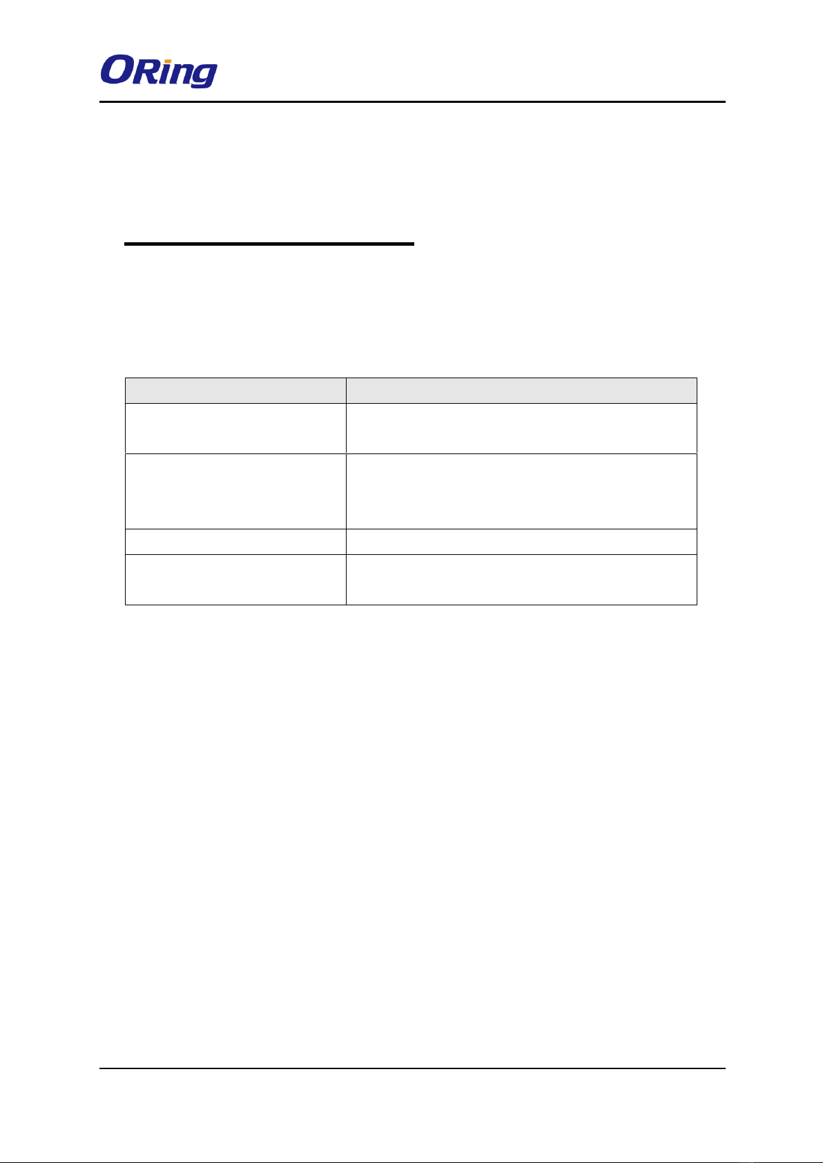
1. Cellular 1 antenna connector
2. WiFi connection LED
3. Storage LED
4. Ring Master LED
5. Ring LED
6. SIM 1 card slot
7. SIM 2 card slot
8. SIM card slot
9. WAN port (P.o.E port)
10. Ethernet port
11. Serial port 1 TX / RX LED
12. Serial port 2 TX / RX LED
13. Power 1 LED
14. Power 2 LED
15. P.o.E LED
16. Fault LED
17. Reset button
18. Serial Port 2
19. Cellular 2 antenna connector
20. Serial port 1
21. Power 1 /2 Connector

IGMG-P83244GC+-D4G User Manual
ORing Industrial Networking Corp. 4
WLAN
Green
On
WLAN is activated (Strength: 1<25%,
2<50%, 3<75%, 4<100%)
Blinking
Transmitting data
2.2 Top Panel
Below are the top panel components of the device:
1. Serial port 1: RS-422/RS-485(2W/4W),
2. Terminal Block, PWR1, PWR2, Relay.
2.3 Rear Panel
1. Wall-mount screw holes
2. DIN-rail screw holes

IGMG-P83244GC+-D4G User Manual
ORing Industrial Networking Corp. 5
Hardware Installation
3.1 DIN-Rail Mounting
The device comes with a DIN-Rail kit in the package. The DIN-Rail kit allows you to fasten
the device to a DIN-Rail.
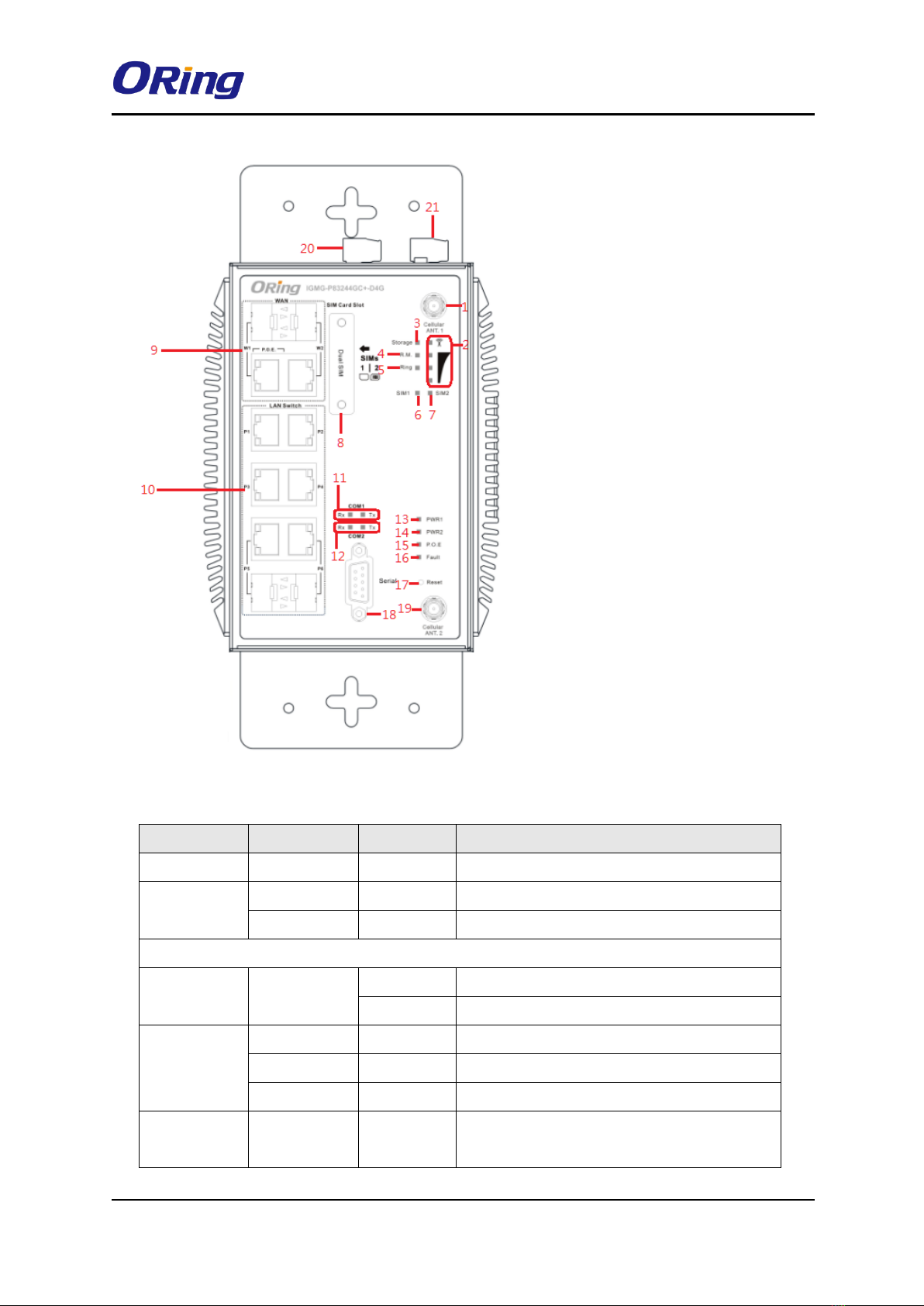
DIN-rail Measurement (Unit = mm)
Installing the device on the DIN-rail is easy. First, screw the Din-rail kit onto the back of the
device, right in the middle of the back panel. Then slide the device onto a DIN-rail from the
Din-rail kit and make sure the device clicks into the rail firmly.
3.2 Wall Mounting
Besides Din-rail, the device can be fixed to the wall via a wall mount panel, which can be
found in the package.
IGMG-P83244GC+-D4G User Manual
ORing Industrial Networking Corp. 6
DIN-rail Measurement (Unit = mm)
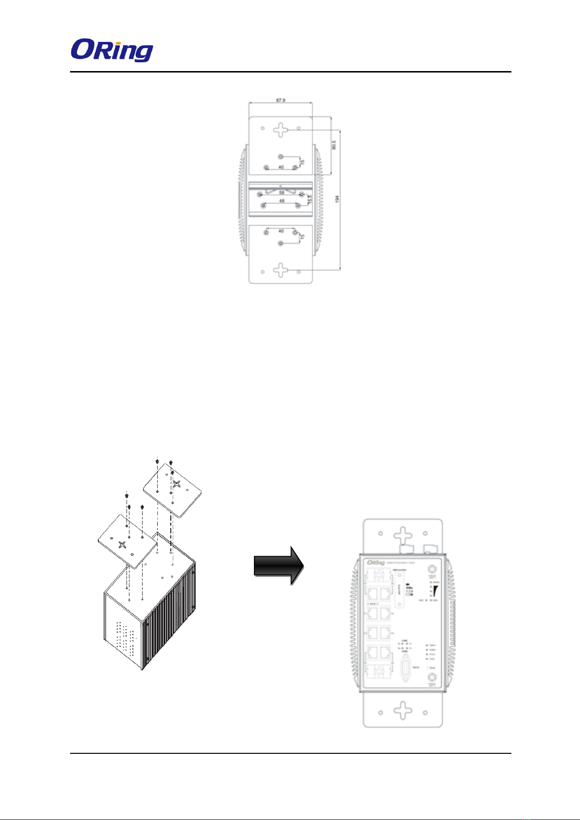
Follow the steps below to install the device to a rack.
Step 1: Screw the two pieces of wall-mount kits onto both ends of the rear panel of the switch.
A total of six screws are required, as shown below.
Step 2: Use the switch, with wall mount plates attached, as a guide to mark the correct
locations of the four screws.
Step 3: Insert a screw through the cross-shaped aperture on the plate, and then slide the
switch downwards. Tighten the screw for added stability.

IGMG-P83244GC+-D4G User Manual
ORing Industrial Networking Corp. 7
3.3 Wiring
WARNING
Be sure to switch off the power and make sure the area is not hazardous before
disconnecting modules or wires. The devices may only be connected to the
supply voltage shown on the type plate.
ATTENTION
1. Be sure to disconnect the power cord before installing and/or wiring your
devices.
2. Calculate the maximum possible current in each power wire and common
wire. Observe all electrical codes dictating the maximum current allowable
for each wire size.
3. If the current goes above the maximum ratings, the wiring could overheat,
causing serious damage to your equipment.
4. Use separate paths to route wiring for power and devices. If power wiring
and device wiring paths must cross, make sure the wires are perpendicular
at the intersection point.
5. Do not run signal or communications wiring and power wiring through the
same wire conduit. To avoid interference, wires with different signal
characteristics should be routed separately.
6. You can use the type of signal transmitted through a wire to determine
which wires should be kept separate. The rule of thumb is that wiring
sharing similar electrical characteristics can be bundled together
7. You should separate input wiring from output wiring
8. It is advised to label the wiring to all devices in the system
3.3.1 Grounding
Grounding and wire routing help limit the effects of noise due to electromagnetic interference
(EMI). Run the ground connection from the ground screw to the grounding surface prior to
connecting devices.
3.3.2 Fault Relay
The two sets of relay contacts of the 6-pin terminal block connector are used to detect
user-configured events. The two wires attached to the fault contacts form an open circuit
when a user-configured when an event is triggered. If a user-configured event does not occur,
the fault circuit remains closed.
3.3.3 Redundant Power Inputs

IGMG-P83244GC+-D4G User Manual
ORing Industrial Networking Corp. 8
The device has two sets of power inputs, power input 1 and
power input 2. The top two contacts and the bottom two
contacts of the 6-pin terminal block connector on the
device’s top panel are used for the two digital inputs. Follow
the steps below to wire redundant power inputs.
Step 1: insert the negative/positive wires into the V-/V+
terminals, respectively.
Step 2: to keep the DC wires from pulling loose, use a small flat-blade screwdriver to tighten
the wire-clamp screws on the front of the terminal block connector.
3.4 SIM Card Installation
After disconnecting the power of the device:
1. Un-fasten the screws.
2. Remove the cover
Note: only remove the cover for SIM card installation. DO NOT remove the cover in
normal operation.
3. Insert the SIM card into the slot.
4. Put the cover back
5. Fasten the screws.
Note: Make sure the power is off before you install the SIM card.

IGMG-P83244GC+-D4G User Manual
ORing Industrial Networking Corp. 9
Cables and Antenna
4.1 Ethernet Pin Definition
The device has standard Ethernet ports. According to the link type, the device uses CAT 3, 4,
5,5e UTP cables to connect to any other network devices (PCs, servers, switches, routers, or
hubs). Please refer to the following table for cable specifications.
Cable Types and Specifications:
Cable
Type
Max. Length
Connector
10Base-T
Cat. 3, 4, 5 100-ohm
UTP 100 m (328 ft)
RJ45
100Base-T(X)
Cat. 5 100-ohm UTP
UTP 100 m (328 ft)
RJ45
1000Base-TX
Cat 5e,6
UTP 100 m (328 ft)
RJ45
With 10/100Base-T(X) cables, pins 1 and 2 are used for transmitting data, and pins 3 and 6
are used for receiving data.
10/100Base-T(X) RJ-45 Port Pin Assignments:
Pin Number
Assignment
1
TD+
2
TD-
3
RD+
6
RD-
1000Base-T RJ-45 Port Pin Assignments:
Pin Number
Assignment
1
BI_DA+
2
BI_DA-
3
BI_DB+
4
BI_DC+
5
BI_DC-
6
BI_DB-
7
BI_DD+
8
BI_DD-
The device supports auto MDI/MDI-X operation. You can use a cable to connect the device to
IGMG-P83244GC+-D4G User Manual
ORing Industrial Networking Corp. 10
a PC. The table below shows the 10/100Base-T(X) MDI and MDI-X port pin outs.
10/100Base-T(X) MDI/MDI-X Pin Assignments:
Pin Number
MDI port
MDI-X port
1
TD+(transmit)
RD+(receive)
2
TD-(transmit)
RD-(receive)
3
RD+(receive)
TD+(transmit)
4
Not used
Not used
5
Not used
Not used
6
RD-(receive)
TD-(transmit)
7
Not used
Not used
8
Not used
Not used
1000Base-T MDI/MDI-X PinAssignments:
Pin Number
MDI port
MDI-X port
1
BI_DA+
BI_DB+
2
BI_DA-
BI_DB-
3
BI_DB+
BI_DA+
4
BI_DC+
BI_DD+
5
BI_DC-
BI_DD-
6
BI_DB-
BI_DA-
7
BI_DD+
BI_DC+
8
BI_DD-
BI_DC-
Note: “+” and “-” signs represent the polarity of the wires that make up each wire pair.
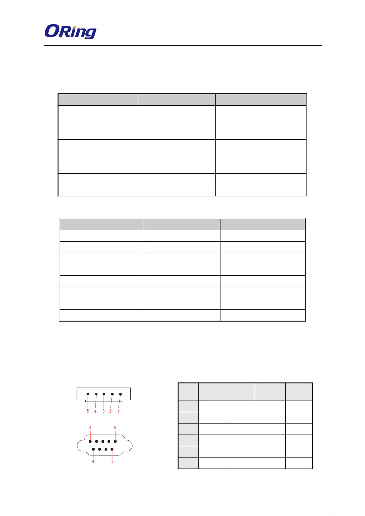
4.2 Serial Port Pin Definition
Com 1 & Com 2
Pin #
RS-232
RS-422
RS-485
(4 wire )
RS-485
(2 wire )
1
DCD
TXD -
TXD -
DATA-
2
RXD
TXD +
TXD +
DATA+
3
TXD
RXD +
RXD +
4
DTR
RXD -
RXD -
5
GND
GND
GND
6
DSR

IGMG-P83244GC+-D4G User Manual
ORing Industrial Networking Corp. 11
4.3 Cellular Antenna
The device provides one cellular connector for a 3G or 4G antenna. External RF cables and
antennas can also be used with the connector.
3G Cellular Antenna
4G LTE Antenna
7
RTS
8
CTS
9
RI
RS 232 mod act as DTE
IGMG-P83244GC+-D4G User Manual
ORing Industrial Networking Corp. 12
Management
5.1 Network Connection
Before installing the Gateway, you need to be able to access the device via a computer
equipped with an Ethernet card or LAN interface. To simplify the connection, it is
recommended to use an Ethernet card to connect to a LAN.
Follow the steps below to install and connect the device to PCs:
Step 1: Select a power source.
Step 2: Connect a computer to the device. Use either a straight-through Ethernet cable or
cross-over cable to connect the ETH1 port of the router to a computer. Once the LED of the
LAN port lights up, which indicates the connection is established, the computer will initiate a
DHCP request to retrieve an IP address from the Gateway.
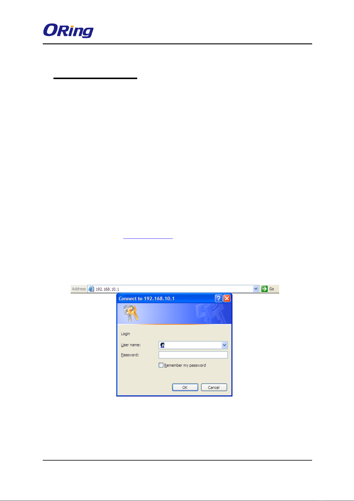
Step 3: Configure the device on a web-based management utility. Open a web browser on
your computer and type http://192.168.10.1 (default gateway IP of the Gateway) in the
address box to access the webpage. A login window will pop up where you can enter the
default login name admin and password admin. For security reasons, we strongly
recommend you to change the password. Click on System Tools > Login Setting after
logging in to change the password.
After you log in successfully, a Web interface will appear, as shown below. On the left hand
side of the interface is a list of functions where you can configure the settings. The details of
the configurations will be shown on the right screen.

IGMG-P83244GC+-D4G User Manual
ORing Industrial Networking Corp. 13
5.2 Configuration
On top of the Home screen shows information about the firmware version, uptime, and WAN
IP address.
Label
Description
Firmware
Shows the current firmware version
Uptime
Shows the elapsed time since the AP router is started
Wan IP
Shows WAN IP address
5.2.1 Basic Setting
This section will guide you through the general settings for the Gateway.
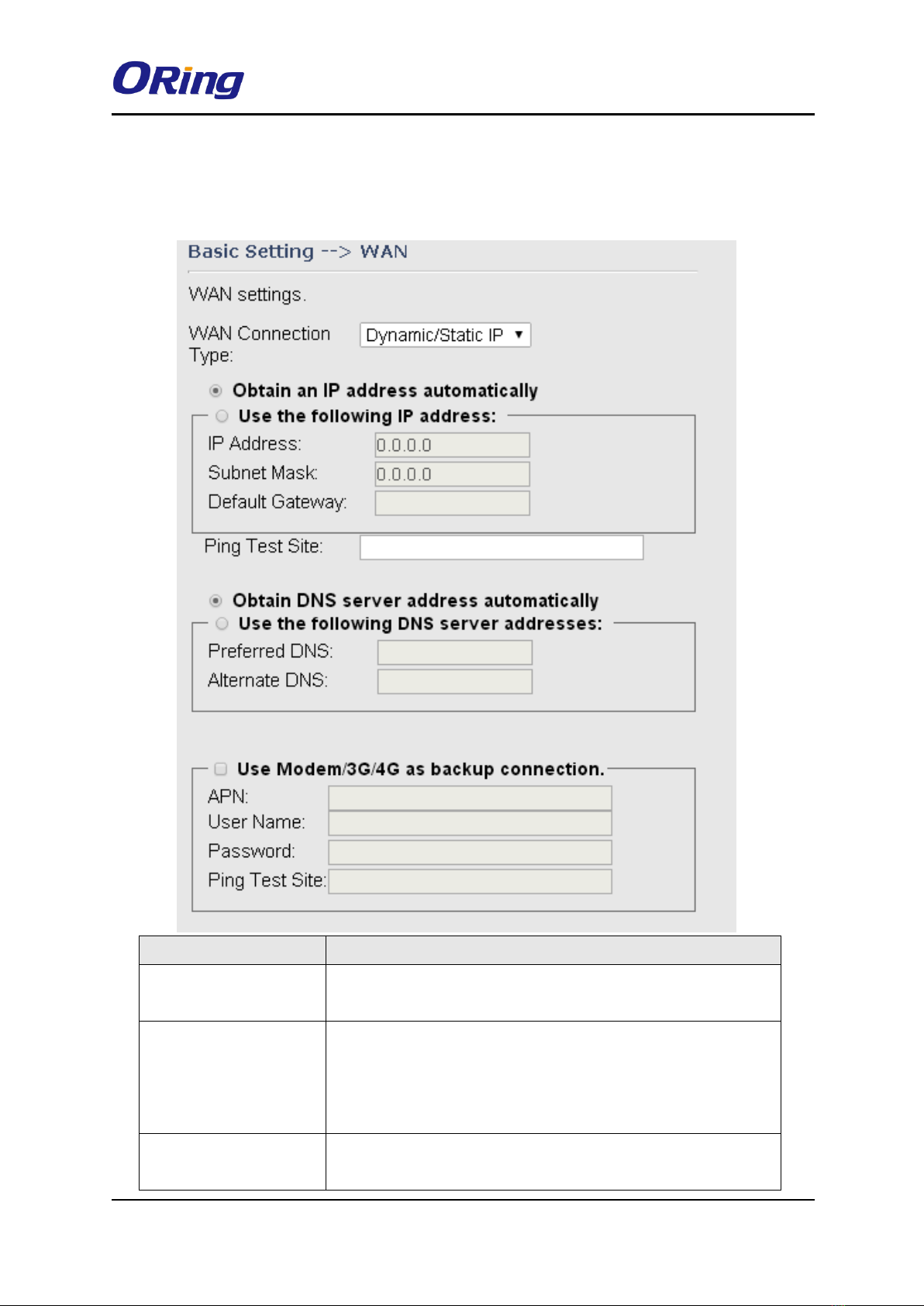
5.2.1.1 WAN
This page allows you to configure WAN settings based on the type of connections you use.
You can consult your ISP if you are unsure of your connection type. If you use the PPPoE
option, make sure any PPPoE client software on your computers is removed or disabled.
WAN Connection Type as Dynamic/Static IP
IGMG-P83244GC+-D4G User Manual
ORing Industrial Networking Corp. 14
Choose this option if your ISP provides you a fixed IP address or the ISP's servers assign the
router's IP addressing upon establishing a connection. You have to manually input the IP
information which is provided by your ISP.
Label
Description
Obtain an IP address
automatically
Select this option if you want the IP address of the WAN port to
be assigned automatically by the DHCP server in your network.
Use the following IP
address
Select this option if you want to assign an IP address to the
WAN port manually. You should set IP Address, Subnet Mask,
and Default Gateway according to IP rules. You can also type a
link in the Ping Test Site field to test your Internet connection
Obtain DNS server
address automatically
Obtains a DNS server address from a DHCP server. If you have
chosen to obtain an IP address automatically, this option will be
IGMG-P83244GC+-D4G User Manual
ORing Industrial Networking Corp. 15
selected accordingly.
Use the following DNS
server addresses
Specifies a DNS server address manually. You can enter two
addresses as the primary and secondary options.
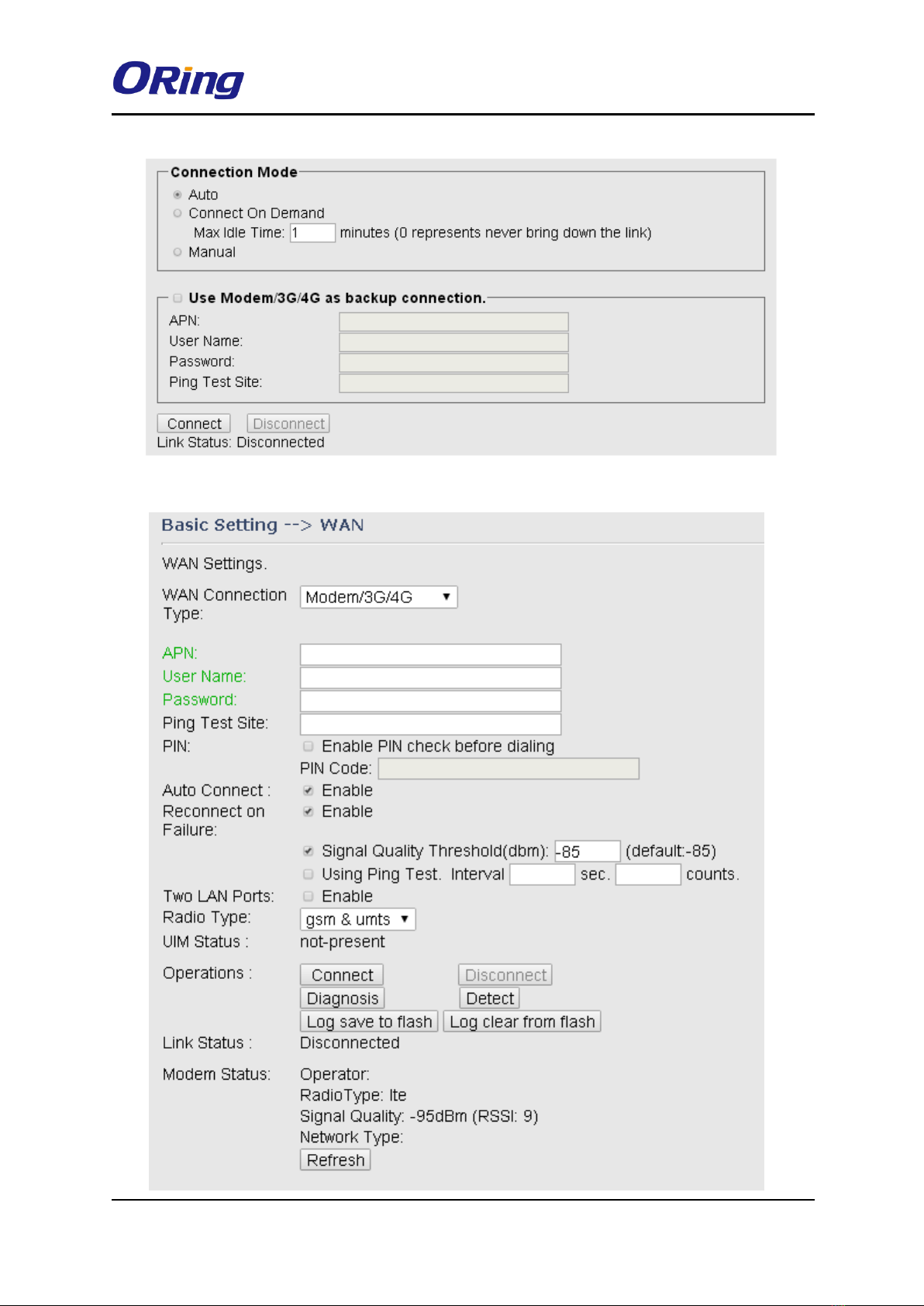
Use Modem/3G as
backup connection
Enable this option if you want to use modem/3G as a backup
connection when main connection is lost.
Enter your account username and password in the
corresponding fields.
Type a website address such as www.google.com in Ping Test
Site to use it to check if the connection is alive or lost.
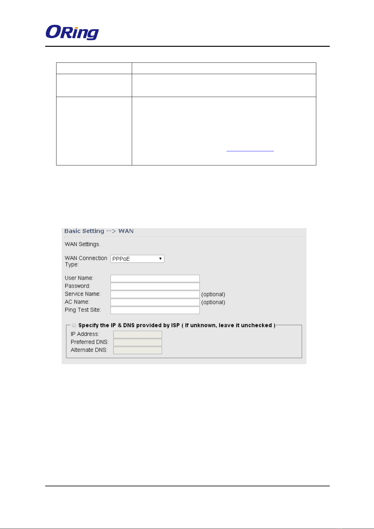
WAN Connection Type as PPPoE
Choose this option if your ISP requires you to use a PPPoE (Point to Point Protocol over
Ethernet) connection. This is a common option for DSL providers. You will need to enter a
username and password
IGMG-P83244GC+-D4G User Manual
ORing Industrial Networking Corp. 16
WAN Connection Type as Modem/3G
Other manuals for IGMG-P83244GC+-D4G
1
Table of contents
Other ORiNG Gateway manuals

ORiNG
ORiNG IMG-W6121+-4G-M12 User manual

ORiNG
ORiNG IMG-W6121+-4G-M12 User manual

ORiNG
ORiNG IMG-4312-MN Series User manual

ORiNG
ORiNG IMG-4312D+-D4G User manual

ORiNG
ORiNG IMG-111 User manual

ORiNG
ORiNG IGMG-P83244GC+-D4G User manual

ORiNG
ORiNG RDS-3086 User manual

ORiNG
ORiNG IMG-111-2G User manual

ORiNG
ORiNG IDS-M311 User manual

ORiNG
ORiNG IDS-M311 User manual


