ORiNG IGMG-P83244GC+-D4G User manual

TX-/ D-
TX+/ D+
RX+
RX-
GND
PWR -1PWR -2
1A@ 24V
DC1 2-48 V
V2- V 2+ V1- V 1+
Fau lt
Quick Installation Guide
Version 1.0
Quick Installation Guide
Introduction
PRINTED ON RECYCLED PAPER
Q I G
is a breakthrough innovation product which is aIGMG-P83244GC+-D4G
combine powerful hardware and software IoT gateway. It is using dual core
ARMv7 Cortex-A9 CPU operating speed up to 1.3 GHz. It integrates 8 ports
industrial Ethernet which 6 ports in switch mode for LAN and 2 ports in
standalone for WAN, and 4 SFP fiber in combo ports and provides LTE 4G
connectivity with AT&T® certification and dual SIM card support. It is also
built in mSATA storage 64GB(optionally up to 256GB) for huge IOT data
collection. There are two serial ports RS232/422/485 and RS422/485 which
both can support Modbus RTU serial protocol to connect with serial devices
and providing all-in-one solutions to help user build up highly reliable and
user-friendly SCADA and IOT system for variant industrial automation
applications. also supports VPN client/serverIGMG-P83244GC+-D4G
including IPsec, OPENSSL VPN. It can provide remote access service
through ORing-PaaS platform and NAT/firewall to protect networking
security.
Package Contents
The device is shipped with the following items. If any of these items is missing
or damaged, please contact your customer service representative for
assistance.
Preparation
Before you begin installing the device, make sure you have all of the package
contents available and a PC with Microsoft Internet Explorer 6.0 or later, for
using web-based system management tools.
Elevated Operating Ambient: If installed in a closed environment, make sure
the operating ambient temperature is compatible with the maximum
ambient temperature (Tma) specified by the manufacturer.
Reduced Air Flow: Make sure the amount of air flow required for safe operation
of the equipment is not compromised during installation.
Mechanical Loading: Make sure the mounting of the equipment is not in a
hazardous condition due to uneven mechanical loading.
Safety & Warnings
Dimension
Panel Layouts
Front View
1. Gigabit Combo port (P5/P6 as LAN port;
W1/W2 as WAN port)
2. Gigabit LAN port
3. LNK/ACT LED for LAN port
4. Link speed indicator for LAN port
5. SIM card slot
6. Data storage LED
7. R.M. status LED
8. Ring status LED
9. WAN connection LED
10. SIM indicator
11. Serial TX/RX LED
12. Power 1 LED
13. Power 2 LED
14. PoE indicator
15. Faulty relay indicator
16. Reset button
17. Serial port
18. Cellular antenna connector
IGMG-P83244GC+-D4G 1907-200-GP83244C+1-FX010
Contents
LTE Antenna
CD
IGMG-P83244GC+-D4G
Pictures Number
X 1
X 2
X 1
QIG
X 2
X 1
Mounting Kit
Rear View
1. Din-rail screw holes
2. Wall-mount screw holes
Step 1: Screw the two pieces of wall-mount kits onto both ends of the rear panel of the
device. A total of six screws are required, as shown below.
Step 2: Use the device, with wall mount plates attached, as a guide to mark the
correct locations of the wall-mounting screws.
Step 3: Insert a screw head through the large part of the keyhole-shaped aperture on the
plate, and then slide the device downwards. Tighten the screw for added stability.
Wall-mounting
9
Step 1: Slant the device and screw the Din-rail kit onto the back of the device, right in the
middle of the back panel.
Step 2: Slide the device onto a DIN-rail from the Din-rail kit and make sure the device clicks
into the rail firmly.
DIN-rail Installation
2
IGMG-P83244GC+-D4G
Bottom View
3
1. Serial port
2. Terminal blocks: PWR1, PWR2
(12-48V DC), Relay
3. Grounding screw
I N D U S T R I A L
M 2 M
G at e w ay
Industrial Cellular M2M Gateway
Circuit Overloading: Consideration should be given to the connection of the equipment
to the supply circuit and the effect that overloading of the circuits might have on overcurrent
protection and supply wiring. Appropriate consideration of equipment nameplate ratings
should be used when addressing this concern.
17
Installation
Network Connection
The device has two 10/100/1000Base-T(X) Ethernet ports. According to the link type, the
device uses CAT 3, 4, 5, 5e, UTP cables to connect to any other network device (PCs,
servers, switches, routers, or hubs). Please refer to the following table for cable
specifications.
IGMG-P83244GC+-D4G
Cellu lar
ANT. 1
SIM Car d Slot
PWR1
PWR2
P.O.E
Reset
COM2
Tx
Tx
Rx
Rx
COM1
10/10 00M
100M
Link
Activ ity
No Link
SIMs
1 2|
Cellu lar
ANT. 2
SIM2SIM1
R.M.
Ring
P.O.E.
P1 P2
P3 P4
W1 W2
P5 P6
Stora ge
WAN
LAN Swi tch
TX-/D -
TX+/D +
RX+
RX-
GND
PWR-1PWR-2
1A@24 V
DC12-48V
V2- V2+ V1- V 1+
Fault
Dual SI M
IGMG-P83244GC+-D4G
Cell ular
ANT. 1
SIM Ca rd Slot
PWR1
PWR2
P.O.E
Rese t
COM2
Tx
Tx
Rx
Rx
COM1
10/1 000M
100M
Link
Acti vity
No Lin k
SIM s
1 2|
Cell ular
ANT. 2
SIM2SIM1
R.M.
Ring
P.O.E.
P1 P2
P3 P4
W1 W2
P5 P6
Stor age
WAN
LAN Sw itch
Dua l SIM
18
185
11
12
13
15
14
16
10
2
3
4
1
1
6
7
8
1
2
2
1
IGMG-P83244GC+-D4G
Cellu lar
ANT. 1
SIM Car d Slot
PWR1
PWR2
P.O.E
Reset
COM2
Tx
Tx
Rx
Rx
COM1
10/10 00M
100M
Link
Activ ity
No Link
SIMs
1 2
|
Cellu lar
ANT. 2
SIM2SIM1
R.M.
Ring
P.O.E.
P1 P2
P3 P4
W1 W2
P5 P6
Stora ge
WAN
LAN Swi tch
Dual S IM
Q I G Quick Installation Guide
Quick Installation Guide
Version 1.0
Q I G
Cable Types and Specifications:
For pin assignments for different types of cables, please refer to the following
tables.
10/100 Base-T(X) RJ-45 port
Pin Number Assignment
1 TD+
2 TD-
3 RD+
4 Not used
5 Not used
6 RD-
7 Not used
8 Not used
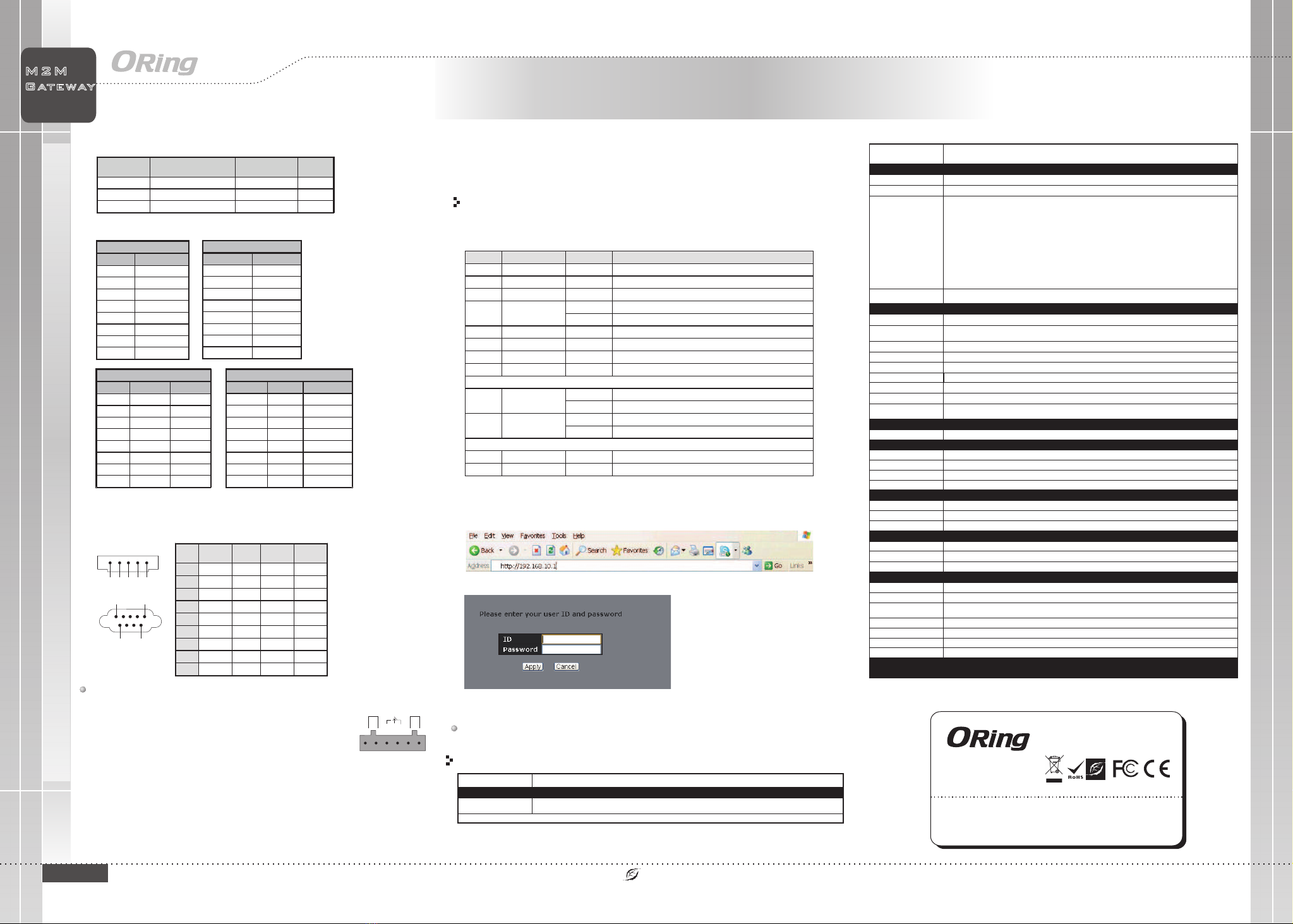
Resetting
To restore the switch configurations back to the factory defaults, press the button for 5 seconds.Reset
1. Launch the Internet Explorer and type in IP address of the switch. The default static IP address is
192.168.10.1
Follow the steps to set up the card:
PRINTED ON RECYCLED PAPER
Cable Type Max. Length Connector
10Base-T Cat. 3, 4, 5 100-ohm UTP 100 m (328 ft) RJ-45
100Base-TX Cat. 5 100-ohm UTP UTP 100 m (328 ft) RJ-45
1000Base-T Cat. 5/Cat 5e 100-ohm UTP UTP 100 m (328 ft) RJ-45
123
4
5
Wiring
Po wer
Redun dan t Inpu t pow er Du al DC i npu ts. 12 ~48 VDC o n 6 pin t erm inal bloc k
Ph ysica l Chara cteri stic
En clos ure I P-3 0
Di mens ion ( W x D x H) 11 6.4m m W x 170 mm D x 15 4mm H ( 4.6 " W x 6.7 " D x 6.1 " H inc h.)
Weig ht (g )
Environ menta l
-4 0 to 85 C (-4 0 to 18 5 F )
o o
St ora ge Temperatu re
5% t o 95% N on- con dens ing
Op era ting H umi dity
RS -232
-4 0 to 75 oC (- 40 to 1 67oF)
Op era ting Temp era tur e
Te chnol ogy
St op Bit s
Da ta Bit s
1, 1 .5, 2
Tx D, Rx D, RTS, CTS, DTR , DSR , DCD, RI, GND
24 00 g
7, 8
Power C ons umpt ion (Typ .) 18 Wat ts
Ov erl oad cu rre nt pro tec tion Pr ese nt
Reverse po larity pr ote ctio n Pre sen t
Se rial Po rts
Co nnec tor Term inal B loc k x 1 (Po rt 1) , DB9 ma le x 1 (Port 2 )
Op era tion M ode
Se rial B aud Rate 1 10 bps t o 921 .6 Kbp s
Port 1 : RS -42 2/RS -48 5(2W /4W ), Whi ch ca n be con fig ured b y uti lity
Port 2 : RS -23 2/RS -42 2/RS -48 5(2W /4W ). Whi ch ca n be con fig ured b y uti lity
RS -422 T x- , Tx+, R x+, R x-, G ND
RS -485 4 w ire : Tx+, T x- , Rx+, R x-, GND
2 wi re: D+ , D-
Parit y odd , eve n, non e, ma rk, sp ace
Regulat ory App roval s
CE E MC (E N 550 24, E N 55032), F CC Part 1 5 B
EM C
EN 5 502 4 (IE C/E N 6100 0-4 -2 (E SD) , IEC /EN 6 100 0-4 -3 (RS), IE C/E N 610 00- 4-4 ( EFT) , IEC /EN 6 100 0-4 -5 (S urg e),
IE C/E N 610 00-4-6 (C S), I EC/ EN 61 000 -4- 8 (PF MF) , IEC/ EN6 100 0-4 -11 (DI P))
EM S
IE C60 068 -2-27
Sh ock
IE C60 068 -2-31
IE C60 068 -2-6
Vi bra tion
Fr ee Fall
Wa rrant y
5 ye ars
EN 609 50- 1
Sa fety
2. Log in with default user name and password (both are admin).
Serial Port Pin Definition
1 5
6 9
Pin #
RS-232
RS-422
RS-485
(4 wire )
RS-485
(2 wire )
1
DCD TXD - TXD - DATA-
2
RXD TXD + TXD + DATA+
3
TXD RXD + RXD +
4
DTR RXD - RXD -
5
GND GND GND
6
DSR
7
RTS
8
CTS
9
RI
The device supports dual redundant power supplies, Power Supply1
(PWR1) and Power Supply 2 (PWR2). The connections for PWR1,
PWR2 and the RELAY are located on the terminal block.
PWR-1PWR-2
1A@24V
V2- V2+ V1- V1+
Fault
Power inputs
The two sets of relay contacts of the 6-pin terminal block connector are used to detect user-
configured events. The two wires attached to the fault contacts form an close circuit when a
user-configured event is triggered. If a user-configured event does not occur, the fault
circuit remains opened.
Relay contact
3.After logging in, you should see the following screen. For more information on configurations,
please refer to the user manual.
I N D U S T R I A L
M 2 M
G at e w ay
Industrial Cellular M2M Gateway
1000Base-T RJ-45 port
Pin Number Assignment
1BI_DA+
2BI_DA-
3BI_DB+
4BI_DC+
5BI_DC-
6BI_DB-
7BI_DD+
8BI_DD-
10/100 Base-T(X) MDI/MDI-X
Pin Number MDI port MDI-X port
1 TD+(transmit) RD+(receive)
2 TD-(transmit) RD-(receive)
3 RD+(receive) TD+(transmit)
4 Not used Not used
5 Not used Not used
6 RD-(receive) TD-(transmit)
7 Not used Not used
8 Not used Not used
Note: “+” and “-” signs represent the polarity of the wires that make up each
wire pair.
1000Base-T MDI/MDI-X
Pin Number MDI port MDI-X port
1 BI_DA+ BI_DB+
2 BI_DA- BI_DB-
3 BI_DB+ BI_DA+
4 BI_DC+ BI_DD+
5 BI_DC- BI_DD-
6 BI_DB- BI_DA-
7 BI_DD+ BI_DC+
8 BI_DD- BI_DC-
Configurations
After installing the device, the green power LED should turn on. Please refer to the
following tablet for LED indication.
Grounding and wire routing help limit the effects of noise due to electromagnetic interference
(EMI). Run the ground connection from the ground screws to the grounding surface prior to
connecting devices.
Grounding
LED
Color
Status
Description
PWR1/2 Green On Power is on and function normally
PoE Green On PoE enabled
Fault Amber On Faulty relay (power failure or port disconnected)
WAN Green On WLAN is activated (Strength: 1<30%, 2 >30% <60%, 3>75%)
Blinking Transmitting data
Storage Green Blinking Data access
R.M Green On Reserved
Ring Green On Reserved
SIM 1/2 Green On SIM card is activated
10/100/1000Base-T(X) Ethernet ports
LNK/ACT Green On Port is connected
Blinking Transmitting data
Speed Amber On Port running at 1000Mbps.
Off Port running at 100Mbps.
Serial ports
Rx Red On Port is receiving data
Tx Green On Port is transmitting data
An tenn a Con nect or
(S MA Fe mal e)
Ce llul ar St anda rd
Ba nd opt ion s
GS M / GPRS / E GPR S / EDGE / W CDM A / HSDPA / HS UPA /HS PA+ /LTE
Am eri ca (US )
LTE :
700/1700/2100MHz
UM TS/HSDPA/H SUPA/H SPA+/D C-H SPA+:
800/850/1900/2100MHz
GS M/GP RS/ EDGE :
850/900/1800/1900MHz
Eu rop e (EU)
LTE :
FD D:21 00( B1)/ 180 0(B3 )/2 600( B7) /900 (B8 )/80 0(B 20) MH z
TD D:TD D:2 600( B38 )/23 00( B40) /25 00(B 41) M Hz
UM TS/HSDPA/H SUPA/H SPA+/D C-H SPA+:
21 00(B 1)/ 900( B8) M Hz
GS M/GP RS/ EDGE :
90 0/85 0 MHz
10 /100 /10 00 Bas e-T( X) Po rts i n
RJ 45 Auto MDI /MDIX 4
Ph ysica l Ports
IG MG-P 83244GC+-D4G
Specifications
OR ing M2M M odel
Gi gabi t Com bo por t wit h
10 /100 /10 00Ba se-T (X) an d
10 0/10 00B ase-X SF P por ts
4
Ce llula r Inter face
MT BF
14 034 5.5 955 h rs
STEP 1: Insert the negative/positive wires into the V-/V+ terminals,
respectively.
To keep the DC wires from pulling loose, use a small flat-bladeSTEP 2:
screwdriver to tighten the wire-clamp screws on the front of the
terminal block connector.
SI M card s lot 2
2
Fault con tact
Relay Rel ay ou tpu t to ca rry c apa cit y of 1A a t 24V DC
EN 5 503 2, CI SPR 32, EN 6100 0-3 -2, E N 610 00- 3-3 ,FC C Par t 15 B cl ass A
EM I
ORing Industrial Networking Corp.
Copyright© 2019 ORing
All rights reserved.
TEL: +886-2-2218-1066
FAX: +886-2-2218-1014
Website: www.oringnet.com
E-mail: support@oringnet.com
IGMG-P83244GC+-D4G
IGMG-P83244GC+-D4G
Other manuals for IGMG-P83244GC+-D4G
1
Other ORiNG Gateway manuals

ORiNG
ORiNG IMG-111-2G User manual

ORiNG
ORiNG IDS-M311 User manual

ORiNG
ORiNG IMG-4312-MN Series User manual

ORiNG
ORiNG RDS-3086 User manual

ORiNG
ORiNG IDS-M311 User manual

ORiNG
ORiNG IGMG-P83244GC+-D4G User manual

ORiNG
ORiNG IMG-111 User manual

ORiNG
ORiNG IMG-4312D+-D4G User manual

ORiNG
ORiNG IMG-W6121+-4G-M12 User manual

ORiNG
ORiNG IMG-W6121+-4G-M12 User manual


