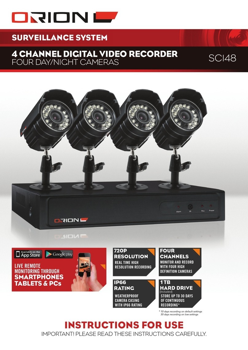
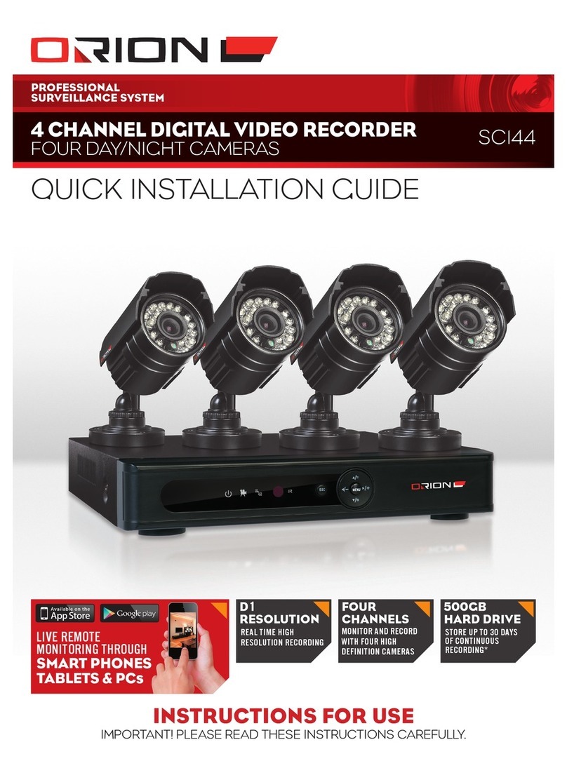
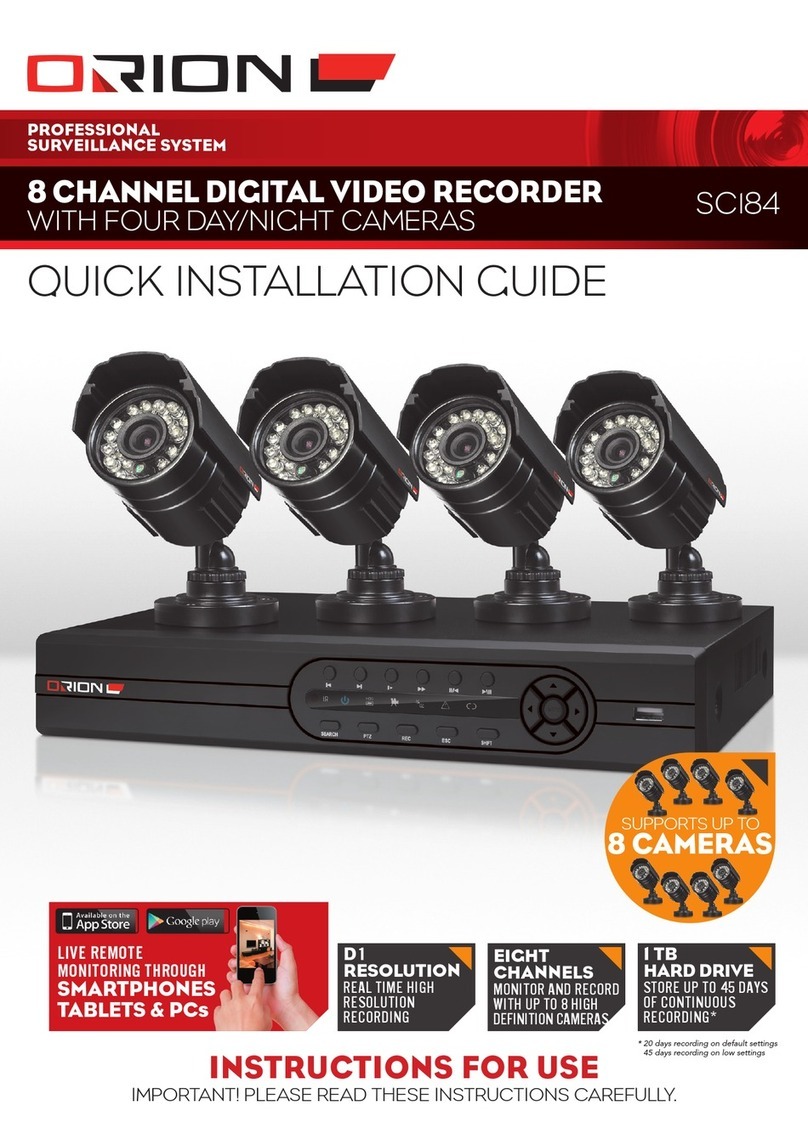
Orion SC184 User manual

INSTRUCTIONS FOR USE
Important! please read these InstructIons carefully.
8 CHANNEL DIGITAL VIDEO RECORDER
wIth four day/nIght cameras sc184
PROFESSIONAL
SURVEILLANCE SYSTEM
1 TB
HARD DRIVE
STORE UP TO 45 DAYS
OF CONTINUOUS
RECORDING*
D1
RESOLUTION
REAL TIME HIGH
RESOLUTION
RECORDING
LIVE REMOTE
MONITORING THROUGH
SMARTPHONES
TABLETS & PCs
EIGHT
CHANNELS
MONITOR AND RECORD
WITH UP TO 8 HIGH
DEFINITION CAMERAS
* 20 days recording on default settings
45 days recording on low settings
supports up to
8 CAMERAS

PROFESSIONAL
SuRvEILLANcE SYSTEM
2
eight channel digital video recorder SC184
1IntroductIon ..................................................... 3
2InstallatIon GuIdelInes .................................. 3
3connectIon dIaGram ...................................... 4
4Hardware layout.............................................. 5
5BasIc dVr operatIon ......................................... 6
6lIVe monItorInG................................................. 6
7loGGInG Into dVr.............................................. 6
8menu layout ....................................................... 7
9record > record conF ................................... 8
10 record > playBack............................................ 8
11 record > Backup ............................................... 9
12 alarm > motIon detect .................................. 9
13 alarm > VIdeo BlInd........................................ 10
14 alarm > VIdeo loss ......................................... 11
15 alarm > alarm Input ...................................... 12
16 alarm > alarm output .................................. 12
17 alarm > aBnormalIty .................................... 13
18 system > General ............................................ 13
19 system > encode conFIG .............................. 14
20 system > network........................................... 14
21 system > net serVIce....................................... 15
22 system > GuI dIsplay ....................................... 17
23 system > ptZ conFIG ....................................... 18
24 ptZ control ...................................................... 19
25 ptZ control - presets .................................... 19
26 ptZ control - patrol...................................... 20
27 ptZ control - pattern ................................... 20
28 ptZ control - Border .................................... 20
29 system > tour................................................... 21
30 system > cHannel type .................................. 21
31 adVanced > Hdd manaGe ............................. 21
32 adVanced > account .................................... 22
33 adVanced > onlIne user ............................... 23
index Page Page
34 adVanced > output adjust ......................... 23
35 adVanced > auto maIntaIn.......................... 23
36 adVanced > restore....................................... 24
37 adVanced > upGrade ..................................... 24
38 adVanced > deVIce InFo ................................ 24
39 adVanced > Import/export.......................... 25
40 InFo > Hdd InFo................................................ 25
41 InFo > Bps ........................................................... 26
42 InFo > loG .......................................................... 26
43 InFo > VersIon .................................................. 26
44 loGout ............................................................... 26
45 cms IntroductIon .......................................... 27
46 cms loGIn .......................................................... 27
47 cms maIn InterFace ........................................ 27
48 cms add dVr ...................................................... 27
49 cms lIVe monItorInG ...................................... 29
50 cms cHannel control .................................. 30
51 cms ptZ control ............................................. 30
52 cms dIsplay ........................................................ 31
53 cms monItor..................................................... 31
54 cms system > user manaGer........................ 32
55 cms system > local settInG ........................ 34
56 cms system > alarm settInG........................ 35
57 cms map control............................................ 35
58 cms playBack .................................................... 36
59 cms Backup conFIG......................................... 37
60 cms loG .............................................................. 37
61 moBIle applIcatIon ......................................... 38
62 trouBlesHootInG GuIde ............................... 40
63 dIGItal VIdeo recorder ................................. 41
64 camera ............................................................... 41
65 warranty........................................................... 42
Customer Service Phone: (03) 9982 5111 (Monday to Friday 8.30am – 5.30pm EST)
Email: [email protected]
For further information visit www.orionlive.com.au
PLEASE CONTACT IF YOU HAVE ANY
CONCERNS OR PROBLEMS WITH THIS PRODUCT
IMPORTANT BEFORE RETURNING THIS
PRODUCT TO THE RETAILER

PROFESSIONAL
SuRvEILLANcE SYSTEM
CPIN002660
3
eight channel digital video recorder SC184
›Do not expose DVR to
extreme temperatures.
›Do not expose DVR to
direct sunlight.
›Do not expose DVR to
collisions or shocks.
›Avoid setting up DVR in
damp environment.
›Do not modify cables and
cameras.
›Avoid setting up DVR in
dusty environment.
›Set up DVR in well ventilated
environment.
›Set up DVR on level and
stable surface.
›Keep the vent clean.
›Do not block the vent.
›Use with supplied power
supply.
›Do not open DVR casing.
›Do not place heavy objects
on the DVR.
›Do not allow any liquid or
solids into the DVR.
1 introduction
2installation guidelines
CAMERA
600TVL
HIGH DEFINITION CAMERA
SENSORS
NIGHT VISION
24 POWERFUL INFRA-RED
LEDS FOR NIGHT VISION
OF UP TO 20 METRES
IP66 RATING
WEATHERPROOF CAMERA
CASING WITH IP66 RATING
DIGITAL VIDEO RECORDER
SMARTPHONE
TABLET & PC
LIVE REMOTE MONITORING
EIGHT
CHANNELS
MONITOR AND RECORD WITH UP
TO 8 HIGH DEFINITION CAMERAS
VGA & HDMI
EASY CONNECTION TO MONITOR
USB
BACKUP RECORDINGS ONTO
FLASH DRIVES OR EXTERNAL
HARD DRIVES
LIVE REMOTE
MONITORING THROUGH
SMARTPHONES
TABLETS & PCs
1TB
HARD DRIVE
STORE UP TO 45 DAYS
OF CONTINUOUS
RECORDING*
EIGHT
CHANNELS
MONITOR AND RECORD
WITH UP TO 8 HIGH
DEFINITION CAMERAS
D1
RESOLUTION
REAL TIME HIGH
RESOLUTION RECORDING
* 20 days recording on default settings. 45 days recording on low settings.

PROFESSIONAL
SuRvEILLANcE SYSTEM
4
eight channel digital video recorder SC184
3 connection diagram
4 Hardware layout
POWER LED
LIT WHEN POWER ON
HARD DRIVE LED
FLASHES DURING DATA
TRANSMISSION BETWEEN
DVR AND HARD DRIVE
NETWORK LED
FLASHES DURING DATA
TRANSMISSION THROUGH
NETWORK
MENU
NAVIGATION
BUTTONS
PLAYBACK
RECORD MODE
USB PORT
RECORD LED
LIT WHEN DVR IS
RECORDING
ALARM LED
LIT WHEN ALARM
TRIGGERED
PLAYBACK
CONTROL
PTZ CONTROL
ESC
RETURN TO PREVIOUS MENU
INFRA-RED RECEIVER
PICKS UP SIGNALS FROM
REMOTE CONTROL
› FRONT PANEL
Connect the other end of video/power
cable (BNC connector only) to BNC video
input on DVR rear panel.
Connect the other end of video/
power cable (DC connector only)
to power splitter.
1
6 7 8 9
2
Connect camera to
video/power cable.
Connect monitor
to DVR VGA
or HDMI video
output.
Connect mouse to
DVR USB input. Connect router to DVR LAN
port using ethernet cable. ACCESSORIES
SPEAKERS
MEMORY
DEVICE
PTZ CAMERA
3 4 Connect camera
power supply to
power splitter and
power point.
Connect DVR
power supply to
DVR power input
and power point.
5
Repeat steps 1 to 3 with
all four cameras.

PROFESSIONAL
SuRvEILLANcE SYSTEM
CPIN002660
5
eight channel digital video recorder SC184
4 Hardware layout
› REMOTE CONTROL
VIEW MODE
SWITCH BETWEEN THE
SINGLE-VIEW AND MULTI-VIEW
MODES
PLAYBACK
ENTER PLAYBACK MENU
NUMBER KEYPAD
CODE INPUT/NUMBER INPUT/
CHANNEL SWITCH
ESC
EXIT AND GO BACK TO
PREVIOUS MENU
NAVEGATION ARROWS
DIRECTIONAL BUTTONS FOR
NAVIGATING THE MENU
MAIN MENU & ENTER BUTTON
BRING UP MAIN MENU OR
CONFIRM SELECTION
PLAY/PAUSE
PLAY BACKWARDS NEXT FILE/ PREVIOUS FILE
FUNCTION BUTTON
ACCESS DVR ASSIST
FUNCTION
SLOW BUTTON
FAST FORWARD
ADD
REMOTE CONTROL CAN CONTROL
MULTIPLE DVR’s. PRESS ADD AND
INPUT CORRESPONDING DVR
NUMBER TO ENABLE REMOTE
CONTROL
RECORD
BRING UP THE RECORD
MODE MENU
PLAYBACK
CONTROL
VGA
VIDEO
OUTPUT
HDMI
VIDEO
OUTPUT
NETWORK PORT
POWER
SWITCH
AUDIO
OUTPUT AUDIO INPUT
COMPOSITE
OUTPUT VIDEO
USB 2.0 PORTS
ALARM AND PTZ PORT
› REAR PANEL
VIDEO INPUT
POWER INPUT
› ALARM INPUT PORT SPECIFICATIONS
›4 channel alarm input.
›Alarm device COM and ground ports are parallel.
›DVR and alarm device share same ground.
›Alarm device NC port must be connected with the DVR
alarm input port.
›Grounding of the power supply and the alarm device must
be shared when used with external power supply.
› ALARM OUTPUT PORT SPECIFICATIONS
›1 channel alarm output.
›Connect to compatible device. Refer to relay specifications
to avoid overloading and damaging the system. Relay model
number is JRC-27F.

PROFESSIONAL
SuRvEILLANcE SYSTEM
6
eight channel digital video recorder SC184
5Basic dVr oPeration
› TURNING ON THE DVR: Make sure the power supply
is connected securely on the rear panel of the DVR. If the
cameras are set up correctly, the live video feed from the
cameras will appear after start up.
› USER INPUT: There are three forms of user input
> MOUSE: The software is designed to be navigated using
a mouse. Left click is to confirm selection and right click is
return to previous menu, display toolbar in live monitoring
screen or display pop down menu in playback screen.
> REMOTE CONTROL: Button layout and functions are
described in 4 Hardware Layout - Remote Control.
> FRONT PANEL: Button layout and functions are
described in 4 Hardware Layout - Front Panel.
›TURNING OFF THE DVR: DVR can be turned off using
menu selection. Enter Main Menu > Logout > Shutdown.
6liVe monitoring
› After system start up, the live video monitoring screen
will be displayed. This allows you to monitor all cameras
simultaneously in real-time.
aCAMERA TITLE:
bDATE AND TIME:
cRECORDING STATUS: Indicate channel being recorded.
dMOTION DETECT: Indicate movement detected.
eVIDEO BLIND: Indicate camera view obscured.
fVIDEO LOSS : Indicate that video feed from camera lost.
gSOUND: Toggle channel sound output.
hTOUR: Toggle tour function.
iTOOLBAR:
Main Menu
PTZ Control Record mode
Color Setting Logout
Output Adjust Single-view
Playback Quad-view
› INTERACTIVE LIVE MONITORING
› Click and drag a box in a particular section of the video
channel for digital zoom.
› Double click any channel to view it in full screen.
› Right click anywhere on the screen to bring up toolbar for
extended functionality.
7logging into dVr
› System login that requests for Username and Password is
required to access DVR Main Menu.
› Default full-permission username is “admin” and no
password. This user profile will allow access to full
functionality of the DVR. The password is disabled by default.
› Default partial-permission username is “guest” and no
password. This user profile will only allow access to video
monitoring and playback. The password is disabled by default.
› User profiles can be customised in Advanced settings.
Refer to 32 Advanced > Account for details.
› It is highly recommended that a strong password is created
as soon as possible to protect your privacy. Create a complex
but memorable password. It is recommended to use at least
8 characters and random mixture of characters such as upper
case, lower case, punctuation and symbols.
Password protection: If the wrong password is entered
10 times consequtively, the profile will be locked.
To unlock the profile, reboot after half an hour and enter the
correct password.

PROFESSIONAL
SuRvEILLANcE SYSTEM
CPIN002660
7
eight channel digital video recorder SC184
Tour
NetService
LOGOUT
INFO
ADVANCED
SYSTEM
ALARM
MAIN
MENU
8menu layout
Logout Shutdown Reboot
Version
BPS
Log
HDD Info
Auto Maintain Restore Upgrade Device Info
Import/Export
HDD Manage Account Online User Output Adjust
GUI Display PTZ Config RS232
General Encode Network
Alarm Input
Motion Detect Video Blind Video Loss
AbnormalityAlarm Output
Record ConfRECORD BackupPlayback

PROFESSIONAL
SuRvEILLANcE SYSTEM
8
eight channel digital video recorder SC184
9record > record conF
Record Conf menu allows the configuration of the way DVR
records video footages. By default, all camera channels are set
to record continuously.
› CHANNEL: Video channel that is being configured. This
number corresponds to the BNC video input on the rear
panel of the DVR.
› REDUNDANCY: Double backup recording files. Two hard
drives required for this functionality. The additional hard
drive must be set to Redundant mode. Refer to 31 Advanced
> HDD Manage for details.
› LENGTH: Duration of recorded files.
› PRERECORD: Duration the DVR records before an alarm
event occurs. This function allows the video footage before,
during and after an event to be recorded. This function
works best in conjunction with Motion Detection to ensure
the entire event is captured.
› MODE: There are three recording modes: Schedule, Manual
or Stop.
› SCHEDULE: Record according to the settings.
>WEEK: Select the day for configuring the record
schedule. Select All to create the same schedule everyday
of the week.
> PERIOD: There are 4 recording periods in every day. Each
period can vary in start time, end time and record trigger.
> REGULAR: DVR records the video footage for the entire
duration of the period.
> DETECT: DVR records the video footage when motion,
video blind or video loss alarms are detected.
> ALARM: DVR records the video footage when alarm input
is triggered.
› MANUAL: Continuous recording.
› STOP: Stop recording.
›ADVANCED:
> UP WINDOW: Return to previous menu.
> SHOW DESKTOP: Exit to main monitoring display screen.
> COPY: Copy current channel settings.
> PASTE: Paste copied channel settings.
> DEFAULT: Restore default settings.
> HDD MANAGE: Open HDD Manage menu.
10 record > PlayBack
Playback allows browsing of recorded video footages in local
hard drive or external storage devices. It is recommended to
play one channel at a time to get the best video quality.
PLAYBACK RECORDED VIDEOS
a RECORD SOURCE: Select source of recording files.
> READ/WRITE: Recording from local hard drive.
> EXTERNAL STORAGE: Recording from external hard
drive or flash drive.
bCALENDAR: Select the date of playback recording.
Highlighted dates determine that recording is available.
cCHANNEL: Select video channels for playback and click
Search button to display recordings on the timeline.
dRECORD TYPE: Select types of recording to be displayed
on timeline.
> REGULAR: Normal recordings recorded within the
scheduled periods without events.
> ALARM: Recordings triggered by motion detect, video
loss, video blind or alarm input.
> MANUAL: Continuous recordings.
eTIMELINE: Shows the recording based on search criteria.
Click any point of the timeline to skip to desired time.
fSYNC MODE: When enabled, all channel playback browsing
are synced in time.
gTIMELINE ZOOM: Click on timeline and select 24hr, 2hr,
1hr or 30mi to zoom into a particular time frame.
hPLAYBACK CONTROL:
Play/Pause Previous Frame
Play Backwards Next Frame
Stop Previous File
Slow Next File
Rewind Replay
Forward Fullscreen
i LIST MODE: List of all recording files based on search criteria.
This mode makes it easy to search for alarm record files.
jMAIN PLAYBACK DISPLAY: Displays playback recordings.
INTERACTIVE PLAYBACK
› Double click any channel to view it in full screen.
› Drag a box in any channel and click on the box to zoom into
a particular region.
a
b
c
i
d
g
f
e
h
j

PROFESSIONAL
SuRvEILLANcE SYSTEM
CPIN002660
9
eight channel digital video recorder SC184
11 record > BackuP
Backup enables stored video recordings in DVR hard drive to be
backed up to external flash drive of hard drive.
BACKING UP RECORDING FILES
aPlug in external storage device such as external hard drive or
flash drive into DVR USB port.
bSelect Detect to search for storage devices connected with
DVR.
cChoose the drive to backup to and select Backup to bring
up the following menu.
dSelect the camera channel, start time, end time and
record type.
eSelect Add to search for recordings that matches the search
criteria. Click on Remove to clear file information.
fCheck the files to backup.
gSelect Begin to start backup operation.
hDuring backup, press Cancel to exit the backup menu. Other
operations can be carried out while the DVR is backing up.
iSelect Stop to stop backing up.
ERASING FILES ON EXTERNAL DRIVE
aSelect Detect to search for storage devices connected
with DVR.
bSelect file to delete.
cSelect Erase to clear selected files.
12 alarm > motion detect
Motion detection is a very powerful function in this DVR that
generates notifications to the user about an event occurring
and trigger the necessary actions to acquire useful video footage.
With this footage, it is easy to distinguish the eventful video
footage from others with no important activity. This can greatly
save time when trying to pin point a desired video footage instead
of filtering through hours of recording manually.
› CHANNEL: Video channel that is being configured.
This number corresponds to the BNC video input on the rear
panel of the DVR.
› ENABLE: Check this box to enable motion detection.
› SENSITIVITY: Calibrate the sensitivity of the motion
detection. This refers to the amount of movement in the
video footage that triggers the motion detect alarm.
› REGION: Setting of which region of the video footage that
is sensitive to motion. Pink blocks are sensitive to motion
detect. Black block is the area unaffected by motion detect.
Click or drag the mouse to toggle the region motion detect
on or off.

PROFESSIONAL
SuRvEILLANcE SYSTEM
10
eight channel digital video recorder SC184
› PERIOD: Motion detection schedule. This schedule can be
customised for each day of the week. Choose All if it is required
to keep the schedule the same for everyday. The green bar
indicates the periods when the motion detection is enabled.
› ALARM OUTPUT: Send signal to connected wired alarm
device when motion detect alarm is triggered.
› DELAY: Duration between motion detect alarm trigger and
signal output.
› INTERVAL: To avoid multiple alarm signals within a short
period of time, the interval duration can be set such that
only one alarm signal is generated even though multiple
motion detect alarm is triggered within that interval.
›RECORD CHANNEL: Multiple channels can be triggered to
record when the current channel triggers motion detect alarm.
›TOUR: Live monitoring screen displays selected channels in
single-view mode when the current channel triggers motion
detect alarm. Refer to 29 System > Tour for details.
›PTZ ACTIVATION: This function requires a PTZ camera to be
installed with the DVR. PTZ camera can be configured to perform
specified actions when motion detect alarm is triggered. PTZ
camera can be set to move to preset viewing direction or
start patrolling. Refer to 23 System > PTZ Config for details.
›DELAY: Duration the DVR continues to record the channel
after motion detect alarm is triggered.
›SHOW MESSAGE: Pop up message on live monitoring
screen when motion detect alarm is triggered.
›SEND EMAIL: DVR automatically sends email to user’s email
account when the motion detect alarm is triggered. Refer to
21 System > Net Service > Email for details.
›BUZZER: DVR emits an alarm tone using its internal buzzer
when the motion detect alarm is triggered.
›FTP UPLOAD: DVR uploads recording files of the alarm
event to the FTP server when the motion detect alarm is
triggered. Refer to 21 System > Net Service > FTP for details.
›ADVANCED:
> UP WINDOW: Return to previous menu.
13 alarm > Video Blind
Video blind is a function that generates alarm signals when the
DVR detects that the camera view is being obscured.
This can be particularly useful when an intruder covers the
camera or redirect the viewing direction.
› CHANNEL: Video channel that is being configured.
This number corresponds to the BNC video input on the rear
panel of the DVR.
› ENABLE: Check this box to enable video blind detection.
› SENSITIVITY: Calibrate the sensitivity of the video blind
detection.
› PERIOD: Video blind detection schedule. This schedule
can be customised for each day of the week. Choose All if
it is required to keep the schedule the same for everyday.
The green bar indicates the periods when the video blind
detection is enabled.
› ALARM OUTPUT: Send signal to connected wired alarm
device when video blind alarm is triggered.
› DELAY: Duration between video blind alarm trigger and
signal output.
›RECORD CHANNEL: Multiple channels can be triggered to
record when the current channel triggers video blind alarm.
›TOUR: Live monitoring screen displays selected channels in
single-view mode when the current channel triggers video
blind alarm. Refer to 29 System > Tour for details.
> SHOW DESKTOP: Exit to main monitoring display screen.
> COPY: Copy current channel settings.
> PASTE: Paste copied channel settings.
> DEFAULT: Restore default settings.
> RECORD CONF: Open Record Config. menu.

PROFESSIONAL
SuRvEILLANcE SYSTEM
CPIN002660
11
eight channel digital video recorder SC184
›PTZ ACTIVATION: This function requires a PTZ camera to be
installed with the DVR. PTZ camera can be configured to
perform specified actions when video blind alarm is triggered.
PTZ camera can be set to move to preset viewing direction or
start patrolling. Refer to 23 System > PTZ Config for details.
›DELAY: Duration the DVR continues to record the channel
after video blind alarm is triggered.
›SHOW MESSAGE: Pop up message on live monitoring
screen when video blind alarm is triggered.
›SEND EMAIL: DVR automatically sends email to user’s email
account when the video blind alarm is triggered. Refer to
21 System > Net Service > Email for details.
›BUZZER: DVR emits an alarm tone using its internal buzzer
when the video blind alarm is triggered.
›FTP UPLOAD: DVR uploads recording files of the alarm event
to the FTP server when the video blind alarm is triggered.
Refer to 21 System > Net Service > FTP for details.
›ADVANCED:
> UP WINDOW: Return to previous menu.
> SHOW DESKTOP: Exit to main monitoring display screen.
> COPY: Copy current channel settings.
> PASTE: Paste copied channel settings
> DEFAULT: Restore default settings.
> RECORD CONF: Open Record Config. menu.
14 alarm > Video loss
Video loss is a function that generates an alarm signal when
the DVR detects that the video feed from the camera is lost.
This can be particularly useful when power or data transmission
between DVR and camera are interrupted or tampered.
› CHANNEL: Video channel that is being configured. This
number corresponds to the BNC video input on the rear
panel of the DVR.
› ENABLE: Check this box to enable video loss detection.
› PERIOD: Video loss detection schedule. This schedule can
be customised for each day of the week. Choose All if it
is required to keep the schedule the same for everyday.
The green bar indicates the periods when the video loss
detection is enabled.
› ALARM OUTPUT: Send signal to connected wired alarm
device when video loss alarm is triggered.
› DELAY: Duration between video loss alarm trigger and
signal output.
›RECORD CHANNEL: Multiple channels can be triggered to
record when the current channel triggers video loss alarm.
›TOUR: Live monitoring screen displays selected channels in
single-view mode when the current channel triggers video
loss alarm. Refer to 29 System > Tour for details.
›PTZ ACTIVATION: This function requires a PTZ camera to
be installed with the DVR. PTZ camera can be configured to
perform specified actions when video loss alarm is triggered.
PTZ camera can be set to move to preset viewing direction
or start patrolling. Refer to 23 System > PTZ Config for details.
›DELAY: Duration the DVR continues to record the channel
after video loss alarm is triggered.
›SHOW MESSAGE: Pop up message on live monitoring
screen when video loss alarm is triggered.
›SEND EMAIL: DVR automatically sends email to user’s email
account when the video loss alarm is triggered. Refer to
21 System > Net Service > Email for details.
›BUZZER: DVR emits an alarm tone using its internal buzzer
when the video loss alarm is triggered.
›FTP UPLOAD: DVR uploads recording files of the alarm
event to the FTP server when the video loss alarm is
triggered. Refer to 21 System > Net Service > FTP for details.
›ADVANCED:
> UP WINDOW: Return to previous menu.
> SHOW DESKTOP: Exit to main monitoring display screen.
> COPY: Copy current channel settings.
> PASTE: Paste copied channel settings.
> DEFAULT: Restore default settings.
> RECORD CONF: Open Record Config. menu.

PROFESSIONAL
SuRvEILLANcE SYSTEM
12
eight channel digital video recorder SC184
15 alarm > alarm inPut
Alarm input enables the alarm ports on the rear panel of the
DVR to trigger specific operation if the DVR. The alarm ports
can be connected to alarm sensor devices.
›ALARM IN: Alarm input channel that is being configured.
This number corresponds to the alarm port on the rear panel
of the DVR.
›TYPE: Type of alarm signal input. Select type according to
connected alarm device.
›PERIOD: Alarm input schedule. This schedule can be
customised for each day of the week. Choose All if it is
required to keep the schedule the same every day. The
green bar indicates the periods when alarm input is enabled.
›ALARM OUTPUT: Send signal to connected wired alarm
device when alarm input is triggered.
›DELAY: Duration between alarm input trigger and signal
output.
›INTERVAL: To avoid multiple alarm signals within a short
period of time, the interval duration can be set such that only
one alarm signal is generated even though multiple alarm
input is triggered within that interval.
›RECORD CHANNEL: Multiple channels can be triggered to
record when current alarm input is triggered.
›TOUR: Live monitoring screen displays selected channels in
single-view mode when the current alarm input is triggered.
Refer to 29 System > Tour for details.
›PTZ ACTIVATION: This function requires a PTZ camera to
be installed with the DVR. PTZ camera can be configured to
perform specified actions when alarm input is triggered. PTZ
camera can be set to move to preset viewing direction or
start patrolling. Refer to 23 System > PTZ Config for details.
›DELAY: Duration the DVR continues to record the channel
after alarm input is triggered.
›SHOW MESSAGE: Pop up message on live monitoring
screen when alarm input is triggered.
›SEND EMAIL: DVR automatically sends email to user’s email
account when alarm input is triggered. Refer to 21 System >
Net Service > Email for details.
›BUZZER: DVR emits an alarm tone using its internal buzzer
when alarm input is triggered.
›FTP UPLOAD: DVR uploads recording files of the alarm
event to the FTP server when alarm input is triggered. Refer
to 21 System > Net Service > FTP for details.
›ADVANCED:
> UP WINDOW: Return to previous menu.
> SHOW DESKTOP: Exit to main monitoring display screen.
> COPY: Copy current alarm settings.
> PASTE: Paste copied alarm settings.
> DEFAULT: Restore default settings.
> RECORD CONF: Open Record Config. menu.
16 alarm > alarm outPut
Alarm output menu enables the setting of the way DVR controls
alarm output.
›CONFIGURATION: DVR controls alarm output according
to alarm input settings. Refer to 15 Alarm > Alarm Input for
details.
›MANUAL: Alarm output turns on.
›STOP: Alarm output turns off.

PROFESSIONAL
SuRvEILLANcE SYSTEM
CPIN002660
13
eight channel digital video recorder SC184
17 alarm > aBnormality
Abnormality refers to any deviation from the DVR’s normal
operation. This function notifies users when any abnormality
occurs.
›EVENT TYPE: There are five event types.
> NO DISK: Hard drive not installed in DVR.
> DISK ERROR: Error occured when read/write hard drive.
> DISK NO SPACE: No storage space in hard drive.
> NET DISCONNECTION: Network connection interrupted.
> IP CONFLICT: DVR IP address conflicting with other device.
›ENABLE: Check this box to enable selected abnormality
detection.
›SHOW MESSAGE: Pop up message on live monitoring
screen when abnormaility detected.
›BUZZER: DVR emits an alarm tone using its internal buzzer
when abnormality detected.
18 system > general
General menu allows configuration of basic system settings.
›SYSTEM TIME: This is the date and time that is used to time
stamp all the video footages, logs and notifications.
›DATE FORMAT: Select preferred date format.
›DST: Daylight savings time is used to reconfigure the time
during daylight savings. Daylight savings differ from country
to country. Enter the dates and times that daylight savings
time applies begins and ends according to locality.
›DATE SEPARATOR: Select preferred separator (/ : .)
›TIME FORMAT: Select preferred time format.
(24 hours or 12 hours)
›LANGUAGE: Select preferred language.
›HDD FULL: The method the DVR handles data storage
when hard disk is full. Overwrite setting overwrites the oldest
recordings with new ones. Stop record setting stops all
recording when hard disk is full.
›DVR NO.: Number allocated to the DVR. Multiple DVR can
share the same remote controller. Only when the matching
number of the DVR and remote control is pressed, the
remote control signals will be recognised by the DVR.
›VIDEO STANDARD: Select video standard (PAL or NTSC).
The video standard in Australia is PAL.
›AUTO LOGOUT: Duration of inactivity to logout the
current user. After auto logout, the user is required to enter
password to resume operation.

PROFESSIONAL
SuRvEILLANcE SYSTEM
14
eight channel digital video recorder SC184
19 system > encode conFig
Encode config allows configuration of the quality video streams
are encoded and recorded. The DVR allows two different
channels of compression.
› MAIN STREAM is for the video streams that are displayed
and recorded by the DVR. Main stream has the best quality
for local viewing.
› EXTRA STREAM is for the video streams transmitted
through the network to mobile devices or remote PC. The
subtream usually has poorer quality to keep the files small,
making it easier to transmit through network and ensure a
smooth video stream.
MAIN
STREAM
EXTRA
STREAM
›CHANNEL: Video channel that is being configured. This
number corresponds to the BNC video input on the rear
panel of the DVR.
›RESOLUTION: Number of pixels in the video. There are
three resolution settings which are D1, HD1 and CIF. It is
recommended to encode all eight channels in D1 resolution
in main stream and CIF resolution in Extra Stream.
> Resolution of D1 is (704x480 NTSC and 704x576 PAL).
> Resolution of HD1 is (704x240 NTSC and 704x288 PAL).
> Resolution of CIF is (352x240 NTSC and 352x288 PAL).
›FRAME RATE (FPS): Number of images frames that are
recorded by the DVR per second. The higher the number,
the smoother the video and higher data transmission.
›BIT RATE TYPE: There are 2 types of bit rate which are
Variable Bit Rate (VBR) and Constant Bit Rate (CBR).
> VBR encoding data consumption can vary by the amount
of data usage over time according to requirement. It
allocates higher bit rate to more complex recordings
such as one with a lot of movement in view. Conversely, it
allocates lower bit rate to recordings with no movements.
It is recommended to use VBR for Main Stream as the DVR
can manage the allocation of data on the hard disk wisely.
> CBR encoding data consumption is always constant per time.
CBR is useful when transmitting data over limited capacity
channels such as networks over the internet. The disadvantage
of CBR is that complex recordings may lose some information
and form fuzzy blocks on the video stream. It is recommended
to use CBR for Extra Stream as it can ensure a constant
stream of video over the internet to remote devices.
›QUALITY: Quality of the video recording. When VBR is
selected, there are 6 quality options of the video stream.
›BIT RATE: Amount of data transmitted over time. The quality
of video recording directly correlates to the bit rate. The higher
the bit rate, the higher quality the video recording. When CBR
is selected, there are 6 bit rate options of the video stream.
›VIDEO/AUDIO: Check the box to enable video or audio
recording.
›ADVANCED:
> UP WINDOW: Return to previous menu.
> SHOW DESKTOP: Exit to main monitoring display screen.
> COPY: Copy current channel settings.
> PASTE: Paste copied channel settings.
> DEFAULT: Restore default settings.
20 system > network
Network menu allows the configuration of basic network settings.
›NET CARD: DVR networking module.
›DHCP: Dynamic Host Configuration Protocol is a networking
function that automatically acquires IP address from a device
in the same network, usually a router. DHCP is usually used
in networks with a lot of devices which makes IP address
management a complex task. All devices in a network need
to own a unique IP address for them to function properly.
DHCP is enabled by default so the following settings will be
acquired automatically.
›IP ADDRESS: IP address is a set of numbers that determine
the address of the DVR in the local network. This number
is used to locate the DVR in the network when trying to
access it with another device. This DVR uses IPv4 addressing
where the IP address consists of four sets of numbers (0-255)
separated by a period.
›SUBNET MASK: This refers to a subdivision of a local IP
network. Subnet mask works in conjunction with IP address
and splits the address into 2 parts which are network prefix
and host identifier. If IP address is 192.168.1.100 and subnet
mask is 255.255.255.0, the network prefix is 192.168.1.0 and
the host identifier is 0.0.0.100.
›GATEWAY: IP address of the router in the local network that
communicates with the larger network, the internet.
›PRIMARY DNS: Domain Name Server translates the IP address
of a device such as 192.168.1.100 into a domain name
such as mydvr.orionlive.com.au. A Domain Name Server is
required for this functionality. For advanced users only.
›SECONDARY DNS: Backup Domain Name Server. In any
case that communication with primary DNS fails, the DVR will

PROFESSIONAL
SuRvEILLANcE SYSTEM
CPIN002660
15
eight channel digital video recorder SC184
communicate with secondary DNS. For advanced users only.
›MEDIA PORT: Port that the DVR utilise to send video stream
and other information through to Orion CMS. Default Media
port is 34567.
›HTTP PORT: Port the DVR utilise to send video stream
and other information through to internet browser.
Default HTTP port is 80.
›HS DOWNLOAD: Enable high speed file download through
the network.
›TRANSFER POLICY: This defines how DVR transfers data
through the network. There are 3 policies.
> ADAPTIVE: Adjusts the data transmission according to
network speed. This setting adjusts on image quality and
fluency based on current network speed.
> QUALITY: Always transfer the best image quality
regardless of network speed. Video fluency may be
adversely affected during low network speed.
> FLUENCY: Always transfer fluent video. This setting
compromises on image quality to improve video fluency
during low network speed.
21 system > net serVice
Net Service menu allows the configuration of network services.
›PPPOE: Point-to-Point Protocol Over Ethernet allows the
DVR to connect to internet using username and password.
Contact Internet Service Provider to obtain username,
password and IP address if local network is connected to
internet using PPPOE. For advanced users only.
›NTP: Network Time Protocol allows the DVR time settings to
be updated automatically by syncing to the time server.
> SERVER IP: IP address of the NTP server. It is
recommended to use the default NTP server,
time.nist.gov.
> PORT: Set the port according to the NTP server. It is
recommended to use the default NTP time.nist.gov port,123.
> TIME ZONE: Select the local time zone.
> UPDATE PERIOD: This determines how often the DVR
communicates with the NTP server to update the time.
It is highly recommended that daylights savings time function
is disabled when using NTP to sync system time.
›EMAIL: This enables the DVR to send notification and alert
messages to users’ email account. This works in conjunction
with the alarm settings.
> SMTP SERVER: Simple Mail Transfer Protocol Server
refers to the address of the email service provider.
> PORT: Set the port according to the SMTP server.
> NEED SSL: Secure Sockets Layer is an encryption protocol
that provides security when communicating the internet.
Some SMTP servers require emails to have SSL. Check this
box based on the SMTP server settings.
> USER NAME: User name of the email account.
> PASSWORD: Corresponding password for the email
account.
> RECEIVER: Email address of the recipient.
> TITLE: Title of the email message.

PROFESSIONAL
SuRvEILLANcE SYSTEM
16
eight channel digital video recorder SC184
It is recommended that a dedicated email account is created
for the DVR to avoid flooding the users’ email account with
alarm messages. Depending on the alarm settings, the DVR
may send many messages if the alarm is triggered frequently.
Here are some of the common email service providers. It is
recommended to use the following providers.
The following shows the SMTP settings for these providers.
EMAIL
SERVICE
PROVIDER
WINDOWS
LIVE MAIL GMAIL YAHOO
Website www.hotmail.
com
www.
gmail.com
mail.yahoo.
com
SMTP Server smtp.live.com smtp.
gmail.com
smtp.mail.
yahoo.com
Port 587 465 465
SSL Yes Yes Yes
›IP FILTER: This allows the users to control IP addresses
that are allowed to access DVR and IP addresses that are
restricted from accessing DVR.
RESTRICTING IP ADDRESS
aSelect Blacklist from Restricted Type.
bEnter the IP address to restrict.
cSelect Add to include entered IP address into Blacklist.
ALLOWING IP ADDRESS
aSelect Whitelist from Restricted Type.
bEnter the IP address to allow.
cSelect Add to include entered IP address into Whitelist.
REMOVING IP ADDRESS:
aSelect list to modify from Restricted Type.
bCheck the IP address to delete from list.
cSelect Delete to exclude IP address from list.
›DDNS: Dynamic Domain Name Server is a server that
communicates with the DVR to update the IP address and
assigns the IP address to a domain name. This allows the
users to connect to their security devices from the internet
using a domain name instead of IP address. Domain name
such as mydvr.orionlive.com.au is a lot easier to remember
than IP address such as 192.227.220.189.
It is recommended to use Orion Live as the DNS Service.
It is a free DNS service hosted by Orion for all Orion
customers. Visit www.orionlive.com.au/DDNS to create an
account and start remote accessing your DVR.
LINKING DVR TO DDNS SERVER
a DDNS TYPE: Select the DDNS Service Provider.
b DOMAIN NAME: Enter the domain name of the DDNS
account such as john.orionlive.com.au. This is the address
users enter into the mobile app or Orion CMS to access
the DVR.
c USER NAME: Enter the User Name of the DDNS account.
This is usually the account email address.
d PASSWORD: Enter the corresponding password of the
DDNS account.
e Select OK to confirm linking DVR to DDNS Server.
›FTP: File Transfer Protocol is a server that is used to
store and backup files on the network. The DVR can send
recordings to the FTP when an alarm is triggered. To use this
functionality, the user must have access to a FTP server.
OrionLive

PROFESSIONAL
SuRvEILLANcE SYSTEM
CPIN002660
17
eight channel digital video recorder SC184
> SERVER IP: IP address of the FTP server.
> PORT: Set the port according to the FTP server.
> USER NAME: Enter the User Name of the FTP account.
> PASSWORD: Enter the corresponding password of the
FTP account.
> ANONYMOUS: Check to access the FTP server as an
anonymous user.
> MAX FILE LENGTH: Maximum file length of the files sent
to FTP server.
> DIRNAME: Directory of the uploaded files.
›UPNP: Universal Plug and Play is a set of networking
protocol that enables devices in a network to discover each
other’s presence and establish network services. Enabling
UPnP will automatically configure the port forwarding on the
router. Make sure the UPnP functionality on the router which
the DVR is connected to is enabled. If the router UPnP is not
enabled or unavailable, manual setting of port forwarding on
the router is necessary.
›MOBILE MONITOR: Mobile Monitoring enables users to
access DVR and monitor cameras using smartphones or
tablets. This port is used to stream video from DVR to mobile
devices. The default mobile port is 34599.
›ARSP: Not applicable for this model.
›WIRELESS CONFIG: Not applicable for this model.
›WIFI: Not applicable for this model.
22 system > gui disPlay
Display menu enables the configuration of the way information
is portrayed on the display.
›CHANNEL TITLE: Select Set to configure titles of individual
channels.
›TIME DISPLAY: Check to display time on the live monitoring
screen.
›CHANNEL TITLE: Check to channel title on the live
monitoring screen.
›RECORD STATUS: Check to display record status on the live
monitoring screen.
›ALARM STATUS: Check to display alarm status on the live
monitoring screen.
›TRANSPARENCY: Calibrate preferred transparency of menu
background. With high transparency, the live monitoring
screen is still visible when customising the settings.
›RESOLUTION: DVR video output resolution.

PROFESSIONAL
SuRvEILLANcE SYSTEM
18
eight channel digital video recorder SC184
APPLYING VIDEO REGIONAL COVER
aSelect channel to apply regional cover.
bCheck the tickbox and select a number to allocate to the
masking region. Up to 4 masking regions can be applied
to a channel.
cSelect Set and drag a box in the channel to apply
masking region.
dRight click to confirm setting the masking region.
MOVING TIME AND CHANNEL TITLE DISPLAY
aCheck the tickbox to select item to move.
bSelect Set to move item.
aSelect time or channel and drag to preferred location.
23 system > PtZ conFig
PTZ Config menu allows the configuration of communication
parameters between Pan/Tilt/Zoom devices and DVR. This DVR
is capable of controlling PTZ cameras.
›CHANNEL: Camera channel that the PTZ device is connected
to. This number corresponds to the BNC video input on the
rear panel of the DVR.
›PROTOCOL: There are numerous supported communication
protocols between DVR and PTZ device. Select the protocol
that matches the device.
›ADDRESS: One DVR can be connected to multiple PTZ
devices. This address is assigned to the PTZ device.
This address is used when communicating with a system
connected to multiple PTZ devices.
›BAUDRATE: Rate of the DVR sending signal or pulses to
the PTZ device. Select the baudrate that matches the PTZ
device.
›DATA BITS: Size of the data information in a communication
packet sent to the PTZ device. Select the data bit size that
matches the PTZ device.
›STOP BITS: Size of the stop information in a communication
packet sent to the PTZ device. Select the stop bit size that
matches the PTZ device.
›PARITY: Parity bit is information included into the
communication packet for error detection. It makes sure
that the packet sent from the DVR is identical to the packet
received by the PTZ device. Select the parity that matches
the PTZ device.

PROFESSIONAL
SuRvEILLANcE SYSTEM
CPIN002660
19
eight channel digital video recorder SC184
24 PtZ control
CONTROLLING PAN/TILT/ZOOM DEVICE
PTZ controls for PTZ devices can be brought up by selecting the
channel on the live monitoring screen and clicking the PTZ icon on
the toolbar .
›SPEED: Movement speed of PTZ camera.
›ZOOM: Select / button to adjust the camera zoom.
›FOCUS: Select / button to adjust the camera focus.
›IRIS: Select / button to adjust the camera iris.
›DIRECTIONAL ARROWS: Control of the PTZ camera in 8
different directions.
›PATROL: Button in the middle of directional arrow initiates
or stops the camera patrol function.
›SET: Bring up menu for setting preset, tour and pattern.
›PTZ TRACE: This function enables camera to trace the
movement of the mouse cursor on the channel.
›PAGE SWITCH: Switch to PTZ extended controls.
The following menu allows the the control of presets, patterns,
tour, autoscan and autopan function. The settings for these
functions are described in following sections.
›PRESET: Enter preset number in No. box and select Preset
to move camera to stored preset position.
›PATTERN: Enter pattern number in No. box and select
Pattern to commence camera pattern movement.
›TOUR: Enter patrol number in No. box and select Tour to
commence camera patrolling function.
›AUTOSCAN: Enter border number in No. box and select
Autoscan to commence camera border scanning movement.
›AUTOPAN: Commence PTZ camera horizontal panning
movement.
›FLIP: Rotate the PTZ camera horizontally by 180°.
›RESET: Clear all PTZ settings.
›PAGE SWITCH: Switch to PTZ auxiliary controls.
The following menu allows the the control of PTZ camera
auxiliary functions. Some cameras have additional mechanism
such as illuminator, wiper, IR filter and others.
›DIRECT AUX OPERATION: List of common PTZ camera
auxiliary function. Select function from list and select Open
or Close to Enable or Disable function.
›AUX NUM OPERATION: Enter auxiliary function number
according to PTZ camera programming. Select Open or
Close to Enable or Disable function.
›PAGE SWITCH: Return to PTZ basic control.
25 PtZ control - Presets
Preset function enables DVR to store the positions of PTZ
camera. These presets can be called to move the camera to
specified position later.
CREATING PRESET
aUsing the directional arrow, move the camera to a desired
viewing position.
bIn PTZ Control menu, select Set to bring up PTZ Config
menu and select Preset function.
cSelect a number for the preset.
dSelect Set to store current camera position to the preset
number.
DELETING PRESET
aIn PTZ Config menu, select Preset function.
bEnter the preset number to delete.
cSelect Del Preset to confirm deleting selected preset.

PROFESSIONAL
SuRvEILLANcE SYSTEM
20
eight channel digital video recorder SC184
26 PtZ control - Patrol
Patrol function enables DVR to move the PTZ camera according
to a list of multiple presets sequentially and continuously.
CREATING PATROL
aIn PTZ Control menu, select Set to bring up PTZ Config
menu and select Tour function. Note that presets need to be
created before including them into patrol list.
b Select a number for the patrol list in Patrol No. box.
cEnter Preset to be added to the patrol list.
d Define the Interval duration for preset. This determines the
duration the camera dwells in current preset position before
moving to the next preset on the patrol list.
e Select Add Preset to confirm adding preset to the patrol list.
f Repeat steps cto dto add more presets into patrol list.
gTo delete preset from patrol list, select a preset and select
Del Preset.
DELETING PATROL
aIn PTZ Config menu, select Tour function.
bSelect the patrol number to delete in Patrol No. box
cSelect Del Tour to delete selected preset.
27 PtZ control - Pattern
Pattern function enables DVR to move the PTZ camera
according to user defined pattern.
CREATING PATTERN
aIn PTZ Control menu, select Set to bring up PTZ Config
menu and select Pattern function.
c Select a number for the Pattern.
dSelect Begin to start creating pattern.
e Create pattern by moving camera using directional arrows
or adjust the focus, zoom and iris. The DVR records the
movement and adjustment and assigns it to the pattern
number.
f In PTZ Control menu, select Set to bring up PTZ Config
menu and select Pattern function.
g Complete pattern setup by, selecting End.
28 PtZ control - Border
Border function enables DVR to move the PTZ camera between
two border positions continuously.
CREATING BORDER
aUsing the directional arrow, move the camera to a
desired left border position.
bIn PTZ Control menu, select Set to bring up PTZ Config
menu and select Border function.
cSelect Left to assign current camera position to the left
border position.
e Using the directional arrow, move the camera to a desired
right border position.
f In PTZ Control menu, select Set to bring up PTZ Config
menu and select Border function.
g Select Right to assign current camera position to right
border position.
Other manuals for SC184
1
Table of contents
Other Orion Security System manuals
Popular Security System manuals by other brands

ABB
ABB M2131xPx-A series operating instructions

Eurotops
Eurotops 36 025 quick start guide

Apxalarm
Apxalarm APX32EN Programming guide

Fortress Automotive Security
Fortress Automotive Security FS-22 operating instructions

Dakota Alert
Dakota Alert CAD-05 Kit GSM owner's manual

Comelit
Comelit 41CPE012EN installation manual