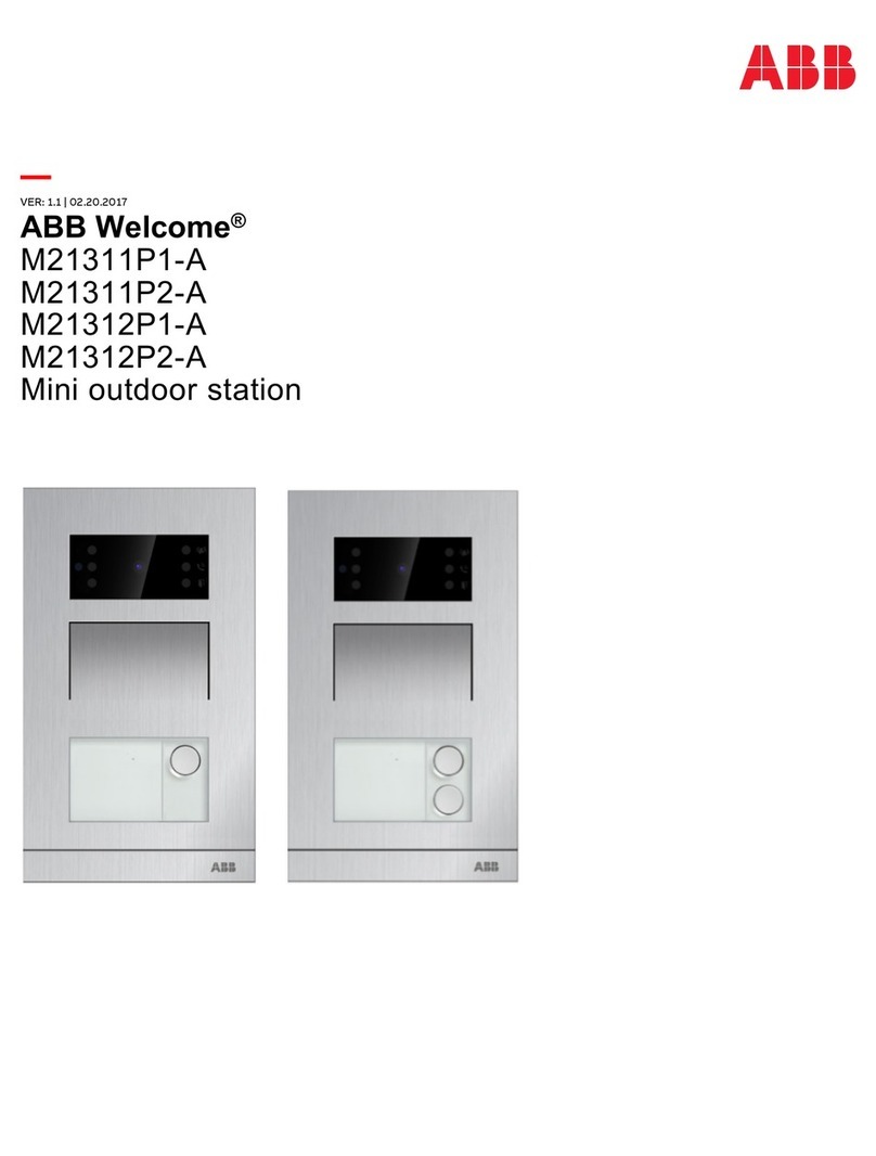
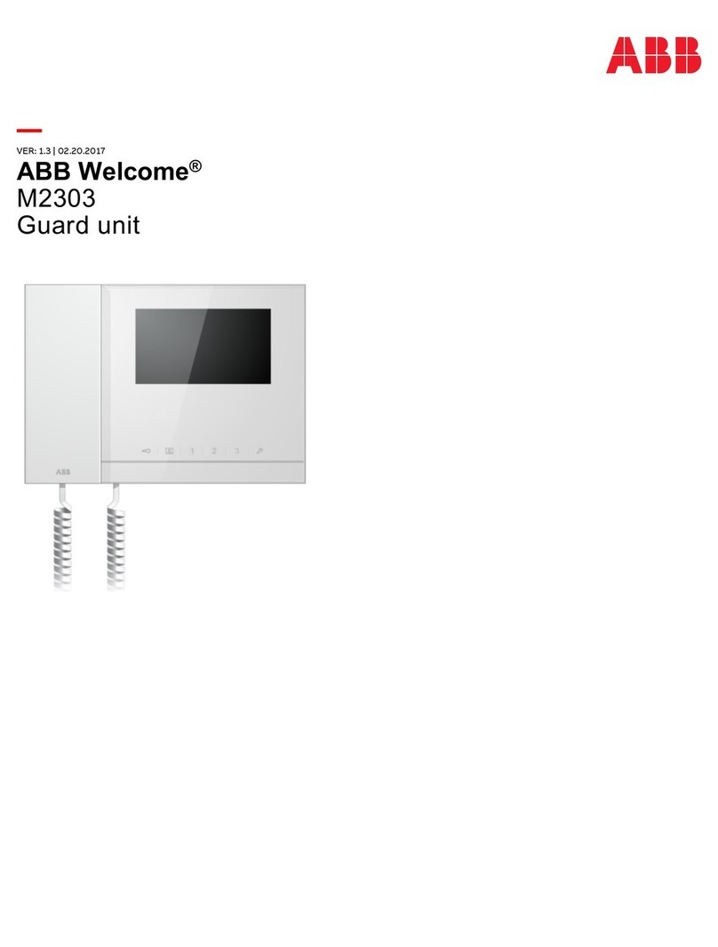
ABB M2131xPx-A series User manual

VER:1.3 │20.06.2017
Operating Instructions
ABB-Welcome
Mini video outdoor station
M2131xPx-A
M2136xPx-A

Table of contents
Operating Instructions VER:1.3 │2
Table of c ontents 1Safety............................................................................................................................................................................3
2Intended use .................................................................................................................................................................3
3Environment..................................................................................................................................................................3
3.1 ABB devices.....................................................................................................................................................3
3.2 Front overview.................................................................................................................................................. 4
3.3 Terminal description......................................................................................................................................... 5
3.4 Lock type and connection ................................................................................................................................ 7
4Technical data...............................................................................................................................................................8
5Mounting/Installation.....................................................................................................................................................9
5.1 Requirement for the electrician........................................................................................................................ 9
5.2 Mounting......................................................................................................................................................... 10
5.2.1 Preparation ..................................................................................................................................................10
5.2.2 Surface mounting.........................................................................................................................................10
5.2.3 Flush mounting ............................................................................................................................................11
5.2.4 Cavity wall installation..................................................................................................................................13
5.2.5 Dismantling..................................................................................................................................................15
5.2.6 Replace the nameplate................................................................................................................................15
5.2.7 Installation situations....................................................................................................................................16
6Commissioning............................................................................................................................................................ 17
6.1 Configure functions of the 1st/2nd pushbutton..............................................................................................17
6.2 Setting general call function...........................................................................................................................19
7Operation .................................................................................................................................................................... 20
7.1 Manage ID cards by mini outdoor station ......................................................................................................20
Notice.................................................................................................................................................................................... 22
Safety
Operating Instructions VER:1.3 │3
1Safety
Warning
Electric voltage!
Dangerous currents flow through the body when coming into direct or indirect
contact with live components.
This can result in electric shock, burns or even death.
– Disconnect the mains power supply prior to installation and/or disassembly!
– Permit work on the 110-240 V supply system to be performed only by
specialist staff!
2Intended use
The outdoor station is an integral part of the ABB-Welcome door communication system and
operates exclusively with components from this system.
3Environment
Consider the protection of the environment!
Used electric and electronic devices must not be disposed of with household
waste.
– The device contains valuable raw materials that can be recycled. Therefore,
dispose of the device at the appropriate collecting facility.
3.1 ABB devices
All packaging materials and devices from ABB bear the markings and test seals for proper
disposal. Always dispose of the packing materials and electric devices and their components via
an authorized collection facility or disposal company.
ABB products meet the legal requirements, in particular the laws governing electronic and
electrical devices and the REACH ordinance.
(EU-Directive 2002/96/EG WEEE and 2002/95/EG RoHS)
(EU-REACH ordinance and law for the implementation of the ordinance (EG) No.1907/2006)

Environment
Operating Instructions VER:1.3 │4
3.2 Front overview
Fig. 1
No Function
1Light sensor
2Infrared LED
3Indicator LED (ring, call and door open)
4Speaker and microphone integration
5Pushbutton
6Nameplate
Tab.1
1
23
4
5
6

Environment
Operating Instructions VER:1.3 │5
3.3 Terminal description
Fig. 2
No Function
1Connector for device software update
2Rotary switch to set the address of outdoor station (1-9)
3Set feedback tone of pushbutton ON/OFF
4Set general call to all indoor stations in one family: ON/OFF
If GC=ON, press button 1/button 2, all IS ring
5
Configuration function of 1st/2nd round pushbutton
5A mini video outdoor station with one pushbutton
3 -> OFF; 4 -> OFF = Call IS 001
3 -> ON; 4 -> OFF = Switch on light
3 -> OFF; 4 -> ON = Call guard unit
3 -> ON; 4 -> ON = Call IS 001
5B mini video outdoor station with two pushbuttons
3 -> OFF; 4 -> OFF = Call IS 001/002
3 -> ON; 4 -> OFF = Switch on light/call IS 001
3 -> OFF; 4 -> ON = Call guard unit/call IS 001
3 -> ON; 4 -> ON = Call IS 001/call IS 002
1
2
3
4
5
6
7
8
9
10
11
12
13

Environment
Operating Instructions VER:1.3 │6
6Set the video mode PAL/NTSC
OFF = PAL video mode
ON = NTSC video mode
7
Set default lock
OFF = set (Lock-GND) as default lock
ON = set (COM-NC-NO) as default lock
*Default lock is controlled by "unlock" button on IS
8Plug-in clamps (a,b) for bus connection
9Plug-in clamps (Exit-GND) for exit button
10 Plug-in clamps (Lock-GND) for door opener
11 Plug-in clamps (COM-NC-NO) for floating output, door opener
12 Rotary switch to adjust default door lock release time, 1-10s
13 Rotary switch to adjust loudspeaker volume
Tab.2

Environment
Operating Instructions VER:1.3 │7
3.4 Lock type and connection
Lock type Operation type Voltage Wiring type
Electrical strike lock,
12 V Power on to open 12 VDC/AC Type A
Type B
Electrical strike lock,
24 V Power on to open 24 VDC/AC Type B
Electrical rim lock, 12 V Power on to open 12 VDC Type A
Type B
Electrical mortise lock Power off to open 12 VDC Type C
Magnetic lock Power off to open 12/24 V DC Type C
Tab.3
Fig. 3
a
b
EXIT
GND
LOCK
COM
NO
NC
a
b
EXIT
GND
LOCK
COM
NO
NC
a
b
EXIT
GND
LOCK
COM
NO
NC
PS
TypeA TypeB Type C
+
-
PS
+
-

Technical data
Operating Instructions VER:1.3 │8
4Technical data
Designation Value
Operating temperature -40 °C - +70 °C
Protection IP 54
Power supply, door opener (Lock-GND) 18 V 4 A impulsive, 250 mA holding
Floating supply, door opener (COM-NC-NO) 30 V DC/AC 1A
Single-wire clamps 2 x 0.28 mm2- 2 x 0.75 mm2
Fine-wire clamps 2 x 0.28 mm2- 2 x 0.75 mm2
Bus voltage 20-30 V DC
Tab.4

Mounting/Installation
Operating Instructions VER:1.3 │9
5Mounting/Installation
Warning
Electric voltage!
Dangerous currents flow through the body when coming into direct or indirect
contact with live components.
This can result in electric shock, burns or even death.
– Disconnect the mains power supply prior to installation and/or disassembly!
– Permit work on the 110-240 V supply system to be performed only by
specialist staff!
5.1 Requirement for the electrician
Warning
Electric voltage!
Install the device only if you have the necessary electrical engineering
knowledge and experience.
– Incorrect installation endangers your life and that of the user of the electrical
system.
– Incorrect installation can cause serious damage to property, e.g. due to fire.
The minimum necessary expert knowledge and requirements for the installation
are as follows:
– Apply the "five safety rules" (DIN VDE 0105, EN 50110):
1. Disconnect
2. Secure against being re-connected
3. Ensure there is no voltage
4. Connect to earth and short-circuit
5. Cover or barricade adjacent live parts.
– Use suitable personal protective clothing.
– Use only suitable tools and measuring devices.
– Check the type of supply network (TN system, IT system, TT system) to
secure the following power supply conditions (classic connection to ground,
protective grounding, necessary additional measures, etc.).

Mounting/Installation
Operating Instructions VER:1.3 │10
5.2 Mounting
5.2.1 Preparation
Use gloves to protect yourself from being cut.
Fig. 4
5.2.2 Surface mounting
Fig. 5
99 mm
26.5 mm
78 mm
1
6
8
m
m
147 mm
①
②

Mounting/Installation
Operating Instructions VER:1.3 │11
5.2.3 Flush mounting
Product dimension
Fig. 6
Mounting without pre-installation box
Fig. 7
90mm
105 mm
Front view Back view Sideview
180mm
168mm
43 mm
90mm
168mm
33mm 10mm

Mounting/Installation
Operating Instructions VER:1.3 │12
Mounting with pre-installation box
Fig. 8
Precautions for installation
When opening a square groove for the lower cover of the equipment, you must
control the embedded depth, ensuring the outer edge of the lower cover can be
fully attached to the wall, but should not leave a large gap between the exposed
parts of the face shell and the wall after the installation of the equipment;
Do not install in raining, humid or dusty environments, and not near objects of
high temperature or strong corrosion.
99 mm
99 mm
45 mm
174mm
174mm
TOP

Mounting/Installation
Operating Instructions VER:1.3 │13
5.2.4 Cavity wall installation
Product dimension
Fig. 9
Installation dimension
Fig. 10
90mm
105 mm
Front view Back view Sideview
180mm
168mm
43 mm
7mm
<29mm
92mm
97mm
170
mm
120 mm

Mounting/Installation
Operating Instructions VER:1.3 │14
Cavity wall installation
Fig. 11

Mounting/Installation
Operating Instructions VER:1.3 │15
5.2.5 Dismantling
Fig. 12
5.2.6 Replace the nameplate
Fig. 13
out
TTL/N
39mm
35mm
in
TTL/N

Mounting/Installation
Operating Instructions VER:1.3 │16
5.2.7 Installation situations
Note
The following installation situations must be avoided without fail to ensure
picture quality.
– Direct light
– Direct sunlight
– Extremely bright picture background
– Highly reflective walls on the opposite side of the door station
– Lamps or direct light sources

Commissioning
Operating Instructions VER:1.3 │17
6Commissioning
6.1 Configure functions of the 1st/2nd pushbutton
Fig. 14
No Function
13-> OFF, 4-> OFF
2Call apartment 001
3 Call apartment 002
Tab.5
Fig. 15:
No Function
13-> OFF, 4-> ON
2Call guard unit
3Call apartment 001
Tab.6
DIP
3 4
0
5
001
002
DIP
3 4
0
5
001
G

Commissioning
Operating Instructions VER:1.3 │18
Fig. 16
No Function
13-> ON, 4-> OFF
2Switch on light
3Call apartment 001
Tab.7
Fig. 17
No Function
13-> ON, 4-> ON
2Call apartment 001
3 Call apartment 002
Tab.8
DIP
3 4
0
5
001
DIP
3 4
0
5
002
001

Commissioning
Operating Instructions VER:1.3 │19
6.2 Setting general call function
Fig. 18
No Function
12-> OFF
2Call apartment 001, both 001 indoor stations ring
3 Call apartment 002, both 002 indoor stations ring
Tab.9
Fig. 19
No Function
12-> ON
2Call apartment 001, all 4 indoor stations (different address) ring
3 Call apartment 002, all 4 indoor stations (different address) ring
Tab.10
* If the "call forward function" has been set at the indoor station, this function will not work well.
For example, 001IS has set call forward to 002 IS, when press 1st round pushbutton on OS to
call 001 IS, if 001 IS doesn’t answer the call in 5s, it will not transfer to 002 IS.
DIP
2
1
2
3
0
5
001 001 002 002
DIP
2
1
2
3
0
5
001 002 003 004

Operation
Operating Instructions VER:1.3 │20
7Operation
M
7.1 Manage ID cards by mini outdoor station
Programming
Function Command Indicated color of door open
Create admin card Swipe card 1x Green
Enter settings Swipe admin card 1x Orange
Tab.11
The system will take the first card swiped after powering up the system within 60s to be the
admin card.
After entering settings, following functionalities can be implemented:
Function Command Indicated color of door open
Enroll user Swipe admin card 1x Orange flash 1x
Swipe user card 1x Green
Delete user Swipe admin card 2x Orange flash 2x
Swipe user card 1x Green
Enroll new admin Swipe admin card 3x Orange flash 3x
Swipe new admin card 1x Green
Delete admin Swipe admin card 4x Orange flash 4x
Swipe other admin card 1x Green
Delete all users Swipe admin card 5x Orange flash quickly
Swipe admin card 1x Green
Tab.12
During setting, please swipe the same admin card.
Function Command Indicated color of door open
Exit settings Swipe admin card 1x or no
cards swiped within 15
seconds --
Tab.13
This manual suits for next models
1
Table of contents
Other ABB Security System manuals

ABB
ABB Arc Guard System TVOC-2 Product manual

ABB
ABB Welcome M2303 User manual

ABB
ABB M2231 SERIES User manual

ABB
ABB 83220 AP-5 series User manual

ABB
ABB Welcome M22344-W User manual

ABB
ABB Welcome M2303 User manual

ABB
ABB M22411-W User manual

ABB
ABB GE GEH4576 User manual

ABB
ABB SACO 16D1 User manual

ABB
ABB ZMT Zirconia User manual
Popular Security System manuals by other brands

Alarm Lock
Alarm Lock PG-10 Installation and operating instructions

Se-Kure Controls
Se-Kure Controls ME Jr. plus 2 SK-800MEI Series installation instructions

Dakota Alert
Dakota Alert AD-01 Kit owner's manual

LevelOne
LevelOne FCS-5008 user manual

Leitch
Leitch asm-6001 user manual

Stacey
Stacey i3 Livelink instruction manual