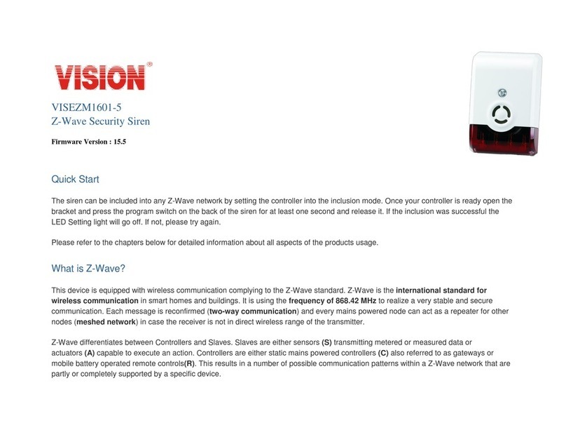
Vision ZM1621MY-5 User manual

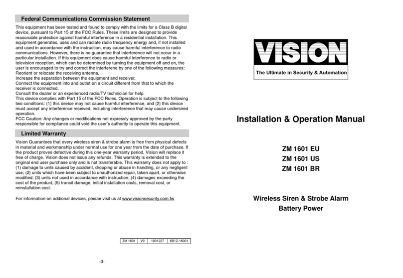
Federal Communications Commission Statement
This equipment has been followed to comply with Part 15 of the FCC Rules. This
equipment generates, uses and can radiate radio frequency energy and, if not installed
and used in accordance with the instruction, may cause harmful interference to radio
communications. However, there is no guarantee that interference will not occur in a
particular installation. If this equipment does cause harmful interference to radio or
television reception, which can be determined by turning the equipment off and on, the
user is encouraged to try and correct the interference by one of the following measures:
-Reorient or relocate the receiving antenna,
-Increase the separation between the equipment and receiver,
-Connect the equipment into and outlet on a circuit different from that to which the
receiver is connected.
Consult the dealer or an experienced radio/TV technician for help.
This device complies with Part 15 of the FCC Rules. Operation is subject to the
following two conditions: (1) this device may not cause harmful interference, and (2) this
device must accept any interference received, including interference that may cause
undesirable operation.
FCC Caution:Any changes or modifications not expressly approved by the party
responsible for compliance could void the user’s authority to operate this equipment.
Limited Warranty
Vision Guarantees that every wireless siren & strobe alarm is free from physical defects
in material and workmanship under normal use for one year from the date of purchase.
If the product proves defective during this one-year warranty period, Vision will replace it
free of charge. Vision does not issue any refunds. This warranty is extended to the
original end user purchase only and is not transferable. This warranty does not apply
to : (1) damage to units caused by accident, dropping or abuse in handling, or any
negligent use; (2) units which have been subject to unauthorized repair, taken apart, or
otherwise modified; (3) units not used in accordance with instruction; (4) damages
exceeding the cost of the product; (5) transit damage, initial installation costs, removal
cost, or reinstallation cost.
For information on addional devices, plesae visit us at www.visionsecurity.com.tw
Installation & Operation Manual
ZM1621IN-5
ZM1621MY-5
ZM1621EU-5
ZM1621RU-5
ZM1621US-5
ZM1621IL-5
ZM1621KR-5
ZM1621HK-5
ZM1621JP-5
ZM1621BR-5
Outdoor Siren Battery Power
ZM 1621-5
V0
1070613

Introduction
Thanks for choosing the Vision’s wireless outdoor siren & strobe alarm of the home security
device. This siren is a Z-Wave™enabled device (interoperable, two-way RF mesh networking
technology) and is fully compatible with any Z-Wave™enabled network and it’s security
framework. Z-Wave™enabled devices displaying the Z-Wave™logo can also be used with it
regardless of the manufacturer, and ours can also be used in other manufacturer’s Z-Wave™
enabled networks. This product will sound a loud siren and flash a strobe light when an alarm
message or alert is received on any Z-Wave™enabled network. When the device is secure
included into Z-Wave network, above communication will be encrypted.
Product Description and Specification
Specification:
Package Content:
Protocol: Z-Wave™(ZM5202)
Frequency Range:
865.22MHz (ZM1621IN-5)
868.10MHz (ZM1621MY-5)
868.42MHz (ZM1621EU-5)
869.00MHz (ZM1621RU-5)
908.42MHz (ZM1621US-5)
916.00MHz (ZM1621IL-5)
920~923MHz (ZM1621KR-5)
919.80MHz (ZM1621HK-5)
922~926MHz (ZM1621JP-5)
921.42MHz (ZM1621BR-5)
Operating Range: Up to 100 feet line of sight
Loud Audible Alarm: > 115db@30cm
LED Strobe Lighting
Operating Temp.: -10°C~ 60°C(14°F~140°F)
Battery: 4pcs x UM-1
1pc
4pcs
4pcs
1pc
ZM 1621
Screws
UM-1 Batteries
User Manual
Z-Wave™Command Classes:
COMMAND_CLASS_ASSOCIATION_GRP_INFO
COMMAND_CLASS_ASSOCIATION_V2
COMMAND_CLASS_BATTERY
COMMAND_CLASS_CONFIGURATION
COMMAND_CLASS_DEVICE_RESET_LOCALLY
COMMAND_CLASS_FIRMWARE_UPDATE_MD_V2
COMMAND_CLASS_MANUFACTURER_SPECIFIC_V2
COMMAND_CLASS_NOTIFICATION_V4
COMMAND_CLASS_POWERLEVEL
COMMAND_CLASS_SECURITY
COMMAND_CLASS_SWITCH_BINARY (mapping COMMAND_CLASS_BASIC)
COMMAND_CLASS_VERSION_V2
COMMAND_CLASS_ZWAVEPLUS_INFO
Installation
Note: If you are installing the entire Z-Wave™ system for the first time, please refer to the installation
guide of Z-Wave™ Interface Controller before installing ZM 1621.
1. Remove the bracket from the siren by press the locking tab, and then gently slide up the siren.
Observe the correct polarity before insert the batteries.
2. Insert the batteries into ZM1621.
3. Using the screws to affix the bracket on the chosen location.
4.
Slide back the front cover, and then the LED light should go off
.
5. LED Status for Z-Wave Network:
After power on, the LED light will flash 25 seconds if the siren has not been included yet.
After power on, the LED light will go off if the siren has been included.
-2-
-1-

6. For “Inclusion” or “Exclusion”in (adding to or removing from) a network: Put the Z-Wave™
Interface Controller into “inclusion”mode, and following its instruction to add the ZM 1621 to
your controller. To get in the “inclusion”mode, get magnet of the bracket to touch the reed
switch on the ZM1621 and separate at once to be included. After setting, the LED Light should
go off, if not, please try again. (After sending one time’s Z-Wave NIF and not be included then
it will send NWI for auto inclusion. The LED light will flash again if the siren has not been
included or the LED light will go off after inclusion.) ZM1621-5 will send NWE if the exclusion
could not be done successfully.
Note:
a. LED light will flash continuously in Exclusion condition.
b. All user and network settings will be cleared and the device reset to factory defaults when
the device is excluded.
For “Association”: the Z-Wave TM interface controller set “Association”, and following its
instruction to associate the ZM1621 with other device. ZM1621 will get into “Sleep” mode for
power saving. Support grouping identifier=1 (lifeline) Support one association group (=Max 5
nodes). “Association” is used for rear cover notification, low battery report and other grouping
devices’chain reaction.
For “Configuration”:
Byte
Value
Parameter 1
(Siren/Strobe Mode)
1
0 (All Enable) - Default
1 (Siren Only)
2 (Strobe Only)
Parameter 2
(Alarm Auto Stop Time)
1
0 (30 seconds) - Default
1 (60 seconds)
2 (120 seconds)
3 (Will Not Automatically Stop)
(Parameter 1) Siren/Strobe Mode: User can change value from 0 to 2 to turn either Siren
sound, Strobe light, or both when triggered.
(Parameter 2) Alarm Auto Stop Time: User can change the duration of siren time when
triggered.
7. Support OTA Firmware update from controller. Please refer to your controller manual.
We recommend to exclude then include the devices from system after OTA.
8. All the rest commands depend on Z-Wave standard.
Operation
1. Normal operation, the LED light will not on.
2. Alarm Mode:
Active: It will active the Alarm Mode after receiving Basic Set (ON) or Binary Switch (ON). The
LED Strobe Light & SIREN will be active according to the Configuration’s setting value.
Stop: It will stop the Alarm Mode after receiving Basic Set (OFF) or Binary Switch (OFF) which
depends on Configuration’s setting value.
Auto Stop: After stopping alarm, it will send Binary Switch Report (0x00)
3. Self-Protection Mode: After put back the bracket over 5 seconds, ZM 1621 will enter the Self-
Protection Mode which will activate LED Strobe Light & SIREN at the same time. The Alarm
Mode will be triggered If the back cover has been opened during the Self-Protection Mode The
Stop method is same as the Alarm Mode. Open the bracket will send notification after 5 seconds;
close the bracket will send another notification after waiting the alarm stop first..
4. Power Level Control:
* Use PowerLevel Set Command to set the RF strength during a specific period.
* Use PowerLevel Test Node Set Command to test the RF strength for specific node.
5. Battery Capacity Detection:
* Use “Battery Get”command to have the battery capacity back in % (hexadecimal)
* Auto Battery Capacity Detection in every 2 hours.
* Low Battery Report when power is lower than 4.6V +/- 0.2V
* Battery Report will be sent by every wake up notification.
6. Security enabled_ Z-Wave controller must be used to fully utilize the product.
7. Support Explorer Frame Function
8. A Security Enabled Z-Wave Controller must be used to fully utilize the products.
9. Power On “Delay Detection Time”: Every Power On will have 10 seconds “Delay Detection
Time” reserved for “Factory Default Reset”. It’s workable only when ZM1621-5 has included.
10. Factory Default Reset: ZM 1621 will reset to factory default when the device has been excluded.
Please use this procedure only in the event that your network primary controllers is missing or
otherwise inoperable!
Alarm
Version 1
Notification
Version 8
Alarm Type
0x07
Alarm Level
0x00 (Trigger) /
0xFF (Non Trigger)
Notification Type
0x07
Notification Event
0x03 (Trigger) /
0x00 (Non Trigger)
-3-
-4-
This manual suits for next models
9
Other Vision Security System manuals

Vision
Vision ZM 1602 IN-5 User manual

Vision
Vision ZM1601 User manual

Vision
Vision ZM1601IN-5 User manual

Vision
Vision VISEZM1601-5 User manual

Vision
Vision 1330B User manual

Vision
Vision ZM 1602 US User manual

Vision
Vision V-LCD1 User manual

Vision
Vision 2310b User manual

Vision
Vision ZM 1601 EU User manual

Vision
Vision XDVR2POSM User manual