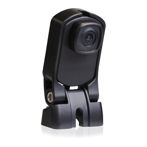
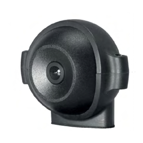
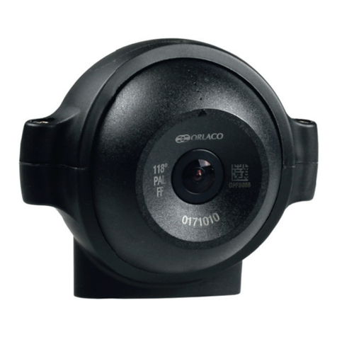
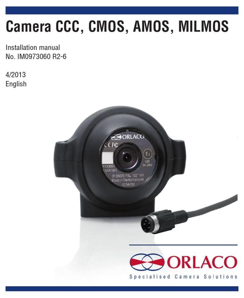
Orlaco AMOS 118 ATVC PAL Mirror User manual

Set Camera
AMOS 118°ATVC PAL Mirror
AMOS 118°ATVC NTSC Mirror
AMOS 102°Maxview ATVC PAL
Installation manual
No. IM0973380 R1-6
Art No: 0400160, 0400180, 0400260
08/2013
English

2IM0973380 R1-6 IM0973380 R1-6 3
Installation manual Installation manual
Safety
In order to guarantee safe operation, these safety
instructions must be read before you start using this
equipment.
• Do not open the enclosure. This can cause damage, short circui-
ting or electrical shocks.
• Do not expose the equipment to extreme temperatures.
This can cause deformation of the enclosure or damage to
internal components.
• Repairs may only be undertaken by the manufacturer.
• The equipment must be assembled as shown in this manual.
Before you start using this equipment, please read this manual
carefully and follow all instructions. This installation manual
describes the functions of the equipment, outlines the
connection options and explains how to put the equipment into
operation. We recommend that you keep this manual in a safe
place for reference purposes.
If you have any questions or issues concerning the operation
of this equipment, consult the relevant section in the manual or
contact the Orlaco Products BV Service department.
The camera/display systems from Orlaco comply with the latest
CE, ADR, EMC and mirror-directive regulations. All products are
manufactured in accordance with the ISO 9001 quality manage-
ment system, ISO/TS16949 quality automotive and ISO 14001
environmental management systems.
Contents page
1. Introduction 3
2. Configuration 3
3. Sets 4
4. Available parts 5
5. ATVC Wiper 6
5. Mounting ATVC 6
6. Adjusting camera lens position 6
7. Cable connections 6
8. Connections and Dimensions 7
8.1. Cable connections 7
8.2. Dimensions 7
9. Connections and Dimensions ATVC I/O box 8
9.1. Front side connections 8
9.2. Dimensions 9
10. Other configurations 10
11. Maintenance and cleaning 11
12. Disposal 11
13. General terms and conditions 11
14. Release notes 11
Set Camera AMOS 118°ATVC PAL Mirror
Art. No. 0400160
Set Camera AMOS 118°ATVC NTSC Mirror
Art. No. 0400260
Set Camera AMOS 102°Maxview ATVC PAL
Art. No. 0400180
Figure 2
Art. No. 0125020;
Camera AMOS 118° ATVC PAL Mirror
Art. No. 0125120;
Camera AMOS 118° ATVC NTSC Mirror
Art. No. 0125030;
Camera AMOS 102° Maxview ATVC PAL
Figure 3, Art. No. 0404190; ATVC I/O Box
1. Introduction
The Sets Camera AMOS ATVC PAL/NTSC, see figure 1, are a
cameras with a automatic cleaning installation. ATVC stands for
All Time Vision Camera. The camera has a self cleaning mode.
The camera lens is build in a glass tube which can rotate via an
industrial stepping motor. Upon activation, water is sprayed onto
the glass surface via a nozzle, the rotation is activated and the
glass surface is cleaned via a build in wiper. The stepping motor is
controlled via the i/o box. The I/O box is included in the set. The I/O
box is for the signals to the camera, see figure 3.
Activation of the cleaning process can be done via the Camera-
Activation signal from the Orlaco monitor (without switcher) or
hard wired directly to the ATVC I/O box.
The ATVC I/O box is powered with a separate dedicated 24V/Dc
powersupply (not via the Orlaco monitor).
The ATVC I/O box supplies power to the Camera and the optional
pump/watertank, see figure 4.
2. Configuration
There are 3 Sets Camera AMOS ATVC available:
• Art. No. 0400160: Set Camera AMOS 118° ATVC PAL Mirror
Art. No. 0125020:
Camera AMOS 118° ATVC PAL Mirror, see figure 2.
Art. No. 0404190:
ATVC I/O Box, see figure 3.
•Art. No. 0400260: Set Camera AMOS 118° ATVC NTSC Mirror
Art. No. 0125120:
Camera AMOS 118° ATVC NTSC Mirror, see figure 2.
Art. No. 0404190:
ATVC I/O Box, see figure 3.
•Art. No. 0400180: Set Camera AMOS 102° Maxview ATVC PAL
Art. No. 0125030:
Camera AMOS 102° Maxview ATVC PAL, see figure 2.
Art. No. 0404190:
ATVC I/O Box, see figure 3.
For complete operation and installation of the set, additional parts
are available.
Figure 1
Art. No. 0400160; Set Camera AMOS 118°
ATVC PAL Mirror
Art. No. 0400260; Set Camera AMOS 118°
ATVC NTSC Mirror
Art. No. 0400180; Set Camera AMOS 102°
Maxview ATVC PAL
Available documentation
Data sheet DS0404190 ATVC I/O Box
Data sheet DS0125020
Camera AMOS 102°/118° ATVC PAL/NTSC
ATVC I/O box
ATVC
4IM0973380 R1-6 IM0973380 R1-6 5
Installation manual Installation manual
In figure 5 the standard system configuration of the system is
shown.
Figure 5
3. Sets
Set Camera AMOS 118° ATVC PAL Mirror (Art. No. 0400160)
Article No. 0125020, Camera AMOS 118° ATVC PAL.
Article No. 0404190, ATVC I/O Box.
Set Camera AMOS 118° ATVC NTSC Mirror (Art. No. 0400280)
Article No. 0125120, Camera AMOS 118° ATVC NTSC.
Article No. 0404190, ATVC I/O Box.
Set Camera AMOS 102° Maxview ATVC PAL (Art. No. 0400180)
Article No. 0125030, Camera AMOS 102° Maxview ATVC PAL.
Article No. 0404190, ATVC I/O Box.
A= Optional cable (Monitor - ATVC I/O box)
B= Optional cable 7p (Camera - ATVC I/O box)
C= Water reservoir + Pump
D = Water hose
24V/DC
Monitor can activate
the ATVC system
Cable
2m Power
24V/DC
Red = Power
White = 0V
Blue = Pulse to activate the ATVC system
Cable included with ATVC I/O box
Monitor
ATVC I/O Box
Art. No. 0404190
ATVC
Art. No. 0125020/120/030
Reservoir
+ Pump
Art. No.
3500810
Optional cable
Optional cable
D Water hose Max. length 11m
Art. No. 2270140
Cable
Red = Power
White = 0V
Cable included
with
ATVC I/O box
24V/DC
Monitor can NOT activate
the ATVC system due to the
use of a camera switcher
Monitor
To ATVC I/O Box
In combination with a Orlaco camera switcher
the ATVC system can only be activated
with the blue wire from the ATVC I/O Box.
Standard conguration
Conguration with Switcher
Set Camera AMOS ATVC PAL
Art. No. 0400160/180/280
0,5m
0,5m
A
B
C
Figure 7
Figure 8
Cable length
100
100
0304***
YM
Label 1
Label 2
CAMERA-END
Molded connector 7pin male Molded connector
7pin female
4. Available parts
Article No. 3500810, ATVC Pomp 24V + Reservoir 6 Liter, including
bracket, see fig. 6.
Article No. 0910230, ATVC adapter bracket; see figure 7, for use in
combination with Adjustable bracket 132mm; Art. No. 2015500 or
Camera extension 250mm; Art. No. 0402270.
Article No. 2270140, Water Hose, all lengths available; Maximum
length 11m. See figure 6a.
Article No. 0304410, Cable 6,0m m7M m7F
Article No. 0304610, Cable 11,0m m7M m7F
Article No. 0304620, Cable 16,0m m7M m7F
Article No. 0305030, Cable 21,0m m7M m7F
Optional Cables 7pins molded male/female connectors; see figure 8.
Figure 6
Figure 6a

6IM0973380 R1-6 IM0973380 R1-6 7
Installation manual Installation manual
Figure 12
25
74
3
6
1
Molded 7p male connector
Front side
100,0
122,4
44,2
97,8
66,4
Units in mm
Camera AMOS 118° ATVC PAL Mirror
Cable 7p male connector 500mm
Water hose, 500mm;
inside: ∅4mm,
outside: ∅7mm
Valve
Attachment plate 2x
74°
6°
Horizontal position
Adjustment
space
Mounting material included
4 x Screw M6 x 20
4 x Washer A 6,4 SS
4 x Nut M6
2 x Attachment plate
Position
Attachment
plate
Figure 11
Figure 10
D
Figure 9
A
A
B
C
5. ATVC wiper, see figure 9.
Turn the two screws Aloose to remove the cover C.
Wiper can be changed at the right side of the camera, see B.
Remove old wiper and place a new wiper; on request.
6. Mounting ATVC
Use the included scews, washers and nuts to mount the ATVC to
your vehicle, see figuur 11, this shows also the right horizontal
position of the ATVC camera.
Note: Use the two Attachment plates for mounting reinforcement.
See figure 11 and 13.
7. Adjusting camera lens position
Remove the cover, as shown in Figure 3. Turn screw D to rotate the
camera and set the camera to the correct position, see Figure 11.
Turn the screw D (Fig. 10) to secure the camera.
Camera is designed to place horizontal, with 74° adjustment for the
camera lens, see figure 11.
8. Connections and dimensions ATVC camera
8.1. Cable connections
Multicable 1 x coax + 5 x wires PVC Ex Art. No. 1220150
1 = Coax = Video
2 = Coax shielding = Video GND
3 = Red = Power
4 = Black = 0V
5 = Orange = Motor -
6 = Yellow = Supply +
7 = Grey = Motor +
8.2. Dimensions
Figure 13

8IM0973380 R1-6 IM0973380 R1-6 9
2
5
7
43
61
1
23
4
25
74
3
6
1
1
3
2
13
2
Installation manual Installation manual
9. Connections and dimensions ATVC I/O box
9.1. Front side connections
To Camera
7p female
1 = Video
2 = Video GND
3 = CAM +12V/DC
4 = CAM - 0V
5 = Motor -
6 = Supply +; Heating camera = Power input after load dump
protection.
7 = Motor +; 7,5V relative to pin 5 = Motor -.
To Monitor
4p male
1 = Video
2 = Video GND
3 = Power 12V/DC
4 = 0V
To Monitor Serial
7p male
1 = Video
2 = Video GND
3 = Power 12...24V/DC
4 = 0V
5 = Tx
6 = Rx
7 = 0V
To pump
3p female
1 = Red = Power 24V/DC
2 = White = 0V
3 = N.C.
To Power input
3p male
1 = Red = Power 24V/DC
2 = White = 0V
3 = Blue = Pulse 12...24V/DC
To Camera
To Monitor
To Monitor Serial
To pump
To Power input
35
units in mm
155
135
∅5,0 (4x)
65
80
Protection cap
included
7p female
connector
4p male
connector
7p male
connector
3p female
connector
3p male
connector
Power cable I/O Box 2m 3p female
Power cable pump
system 2m 3p male
Connector
3p female CE 423
Connector
3p male CE 423
Label 1
Label 2
2000
2000
100
Power Cable
12-24V/DC
Label 1
Power Cable
Pump system
Label 2
100
Camera
Monitor
Monitor
pump
power input
Figure 14 Figure 15
9.2. Dimensions
See figure 15.

10 IM0973380 R1-6 IM0973380 R1-6 11
Installation manual Installation manual
11. Maintenance and cleaning
This product can only work correctly by using fluid for glass
cleaning use in the automotive industry with desired temperature
of -40°C to +85°C. Do absolutely not use aggressive chemicals or
abrasive cleaning agents.
12. Disposal
Disassembly, removal and disposal. Local regulations for dealing
with waste must be followed when disposing of disassembled
components or entire units.
13. General terms and conditions
Orlaco Products BV is not liable for damage resulting from
inadequate servicing, incorrect usage or alterations made to the
equipment without informing the manufacturer in writing.
This installation manual has been made available by Orlaco
Products BV. All rights reserved. No part of this manual may be
reproduced and/or made public in printed form, in photocopy
form or on microfi lm, or in any other way, without the prior
written permission of Orlaco. This also applies to the associated
drawings and figures.
Orlaco reserves the right to make changes to components at any
time without informing customers beforehand or directly. All
dimensions given are for commercial purposes.
For information regarding repairs that is not covered in this
manual, please contact the Orlaco Products BV service department.
This manual has been prepared with all due care and attention.
However, Orlaco Products BV cannot be held responsible for any
errors in this manual or any consequences thereof.
14. Release notes
R1-0 First edition; August 2013.
R1-1 Several changes and additions, October 2013.
R1-2 Set Camera AMOS 102° Maxview ATVC PAL added, November 2013.
R1-3 Set Camera AMOS 102° Maxview ATVC NTSC Mirror added, January 2013.
R1-4 Art. no. Set Camera AMOS 118° ATVC NTSC Mirror changed to 0400260, September 2014.
R1-5 Attachment plate added in chapter 6. July 2015.
R1-6 Text added in chapter 9. April 2016.
10. Other congurations
10.1. Conguration with Switcher
In combination with a Orlaco camera switcher
the ATVC system can only be activated
with the blue wire from the ATVC I/O Box.
When connecting the Set Camera AMOS 118° ATVC PAL MIRROR
to a non Orlaco monitor, the I/O box must be powered via the
monitor output (min 12V), this is next to the power to the I/O box.
When connecting the waterpump from the vehicle to the Set
Camera AMOS 118° ATVC PAL MIRROR the requirements of the
water at the nozzle are: min pressure at nozzle of 1.8Bar. with a
minimum flow of 1.0 l/min.
24V/DC
Monitor can NOT
activate the
ATVC system
due to the
use of a
camera switcher
Monitor
To ATVC I/O Box
Figure 16

ORLACO
Orlaco is a Manufacturing company that specializes in making
cameras and monitor systems for commercial vehicles, fork-lift
trucks, cranes, off shore and maritime.
Our objective is to design and produce camera systems for the
professional market that improve the drivers’ view and increase
operating efficiency.
At our facility in Barneveld we locate our design, manufacturing,
warehousing and service department.
Vision is our mission. Orlaco therefore deploys the development,
manufacture, supply and service of camera and display systems
that will improve safety and efficiency of all vehicles, machinery
and vessels. Our systems give the end user a view on each blind
spot and will create comfort and improved working conditions.
Our active approach will support market demands and
innovations and will lead to enthusiastic ambassadors in the
market; our customers.
This manual suits for next models
5
Table of contents
Other Orlaco Digital Camera manuals

Orlaco
Orlaco Camera EMOS Ethernet with Ex housing User manual

Orlaco
Orlaco AFZ Sst User manual

Orlaco
Orlaco 0103481 User manual

Orlaco
Orlaco 0401432 User guide

Orlaco
Orlaco Set Camera HMOS CornerEye User manual

Orlaco
Orlaco FAMOS User manual

Orlaco
Orlaco HMOS User manual

Orlaco
Orlaco 0506972 User manual

Orlaco
Orlaco CCC User manual

Orlaco
Orlaco RadarEye User guide