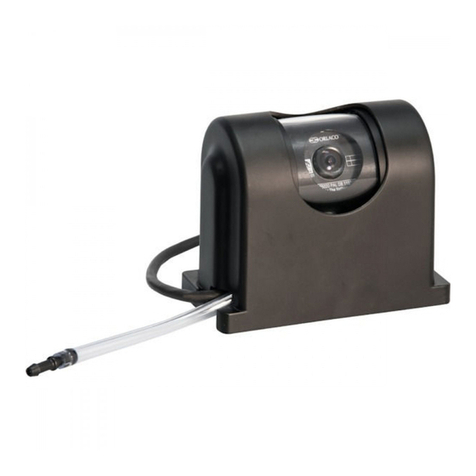
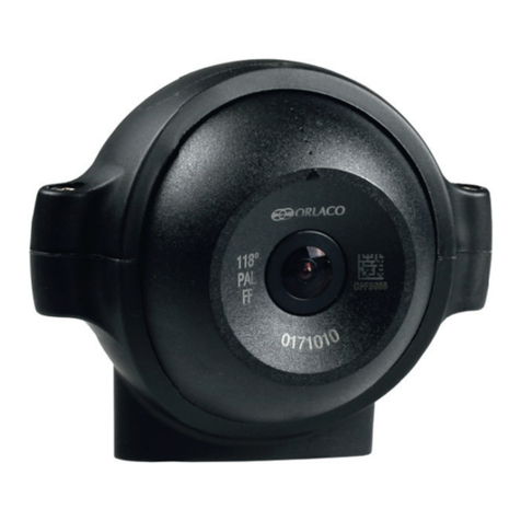
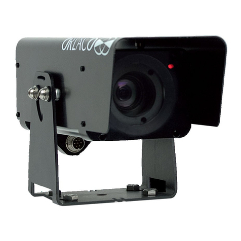
Orlaco CCC User manual

Camera CCC, CMOS, AMOS, MILMOS
Installation manual
No. IM0973060 R2-6
4/2013
English

IM0973060 R2-6
2
Before you start using this equipment, please read this manual carefully and
follow all instructions. We recommend that you keep this manual in a safe place
for reference purposes.
If you have any questions or issues concerning the operation of this equipment,
consult the relevant section in the manual or contact the Orlaco Products BV
Service department.
The camera/display systems from Orlaco comply with the latest CE, ADR, EMC
and mirror-directive regulations. All products are manufactured in accordance
with the ISO 9001 quality management, IATF16949 quality automotive and
ISO 14001 environmental management.
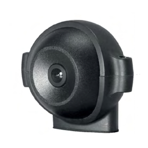
Compact Camera
Type: CCC,CMOS, AMOS, AMOS IR LED, MILMOS
Safety
In order to guarantee safe operation, these safety instructions must
be read before you start using this equipment.
• Do not open the enclosure. This can cause damage, short-circuiting or
electrical shocks.
• Do not expose the equipment to extreme temperatures. This can cause
deformation of the enclosure or damage to internal components.
• Repairs may only be undertaken by the manufacturer.
• The equipment must be assembled as shown in this manual.
Installation manual

3
Contents page
1. Mounting and connecting Camera 4
1.1. Universal camera bracket 4
1.2. Camera attachment 4
1.3. Aiming the camera 5
1.4. Mounting the standard cable with molded connectors 6
1.5. Finish 6
1.6. Camera with solded connectors 7
1.7. Screw connection 7
1.8. Tape 8
1.9. Finish 8
1.10. Camera AMOS IR LED mounting instructions 9
2. Pin connection 10
3. Maintenance and cleaning 12
4. Disposal 12
5. General terms and conditions 13
6. Revision details 14
Installation manual

IM0973060 R2-6
4
1. Mounting and connecting Camera
Overhead
0,5m
0,5m
Recommendation: The bracket should be tightened with
a torque of 11 Nm ± 1 Nm (Equal to the preferred torque
for an M6 bolt.
25
55
∅6,5mm
M6 x 20
Min. bend radius
(R) = 50mm
rubber grommet
inside cabin
outside cabin
Units in mm
Units in mm
55 1m
19
12
3
4
25
M6 x 20
∅6,5mm
1000mm
55
25
M6 x 20
∅6,5mm
55
Units in mm
0,5 m
19
25
M6 x 20
Min. bend radius
(R) = 50mm
∅6,5mm
Min. bend radius
(R) = 50mm
∅19mm
0,5m
rubber grommet
inside cabin
outside cabin
∅19mm
Min. bend
radius (R) = 50mm
Horizontal
Vertical Sloping surfaces
0,5m
Horizontal
Overhead
Vertical Sloping surfaces Units in mm
55 6m
12
3
4
25
M6 x 20
∅6,5mm
Min. bend radius
(R) = 50mm
55
Units in mm
0,5 m
25
M6 x 20
Min. bend radius
(R) = 50mm
∅6,5mm
Lock the connection by screwing
the ring nuts.
Vaseline
19
Overhead
0,5m
0,5m
Recommendation: The bracket should be tightened with
a torque of 11 Nm ± 1 Nm (Equal to the preferred torque
for an M6 bolt.
25
55
∅6,5mm
M6 x 20
Min. bend radius
(R) = 50mm
rubber grommet
inside cabin
outside cabin
Units in mm
Units in mm
55 1m
19
12
3
4
25
M6 x 20
∅6,5mm
1000mm
55
25
M6 x 20
∅6,5mm
55
Units in mm
0,5 m
19
25
M6 x 20
Min. bend radius
(R) = 50mm
∅6,5mm
Min. bend radius
(R) = 50mm
∅19mm
0,5m
rubber grommet
inside cabin
outside cabin
∅19mm
Min. bend
radius (R) = 50mm
Horizontal
Vertical Sloping surfaces
0,5m
Horizontal
Overhead
Vertical Sloping surfaces Units in mm
55 6m
12
3
4
25
M6 x 20
∅6,5mm
Min. bend radius
(R) = 50mm
55
Units in mm
0,5 m
25
M6 x 20
Min. bend radius
(R) = 50mm
∅6,5mm
Lock the connection by screwing
the ring nuts.
Vaseline
19
1.2. Camera attachment.
Recommendation:
The bracket should be tightened with a torque of 6 Nm nominal.
Tighten by hand or with very low speed.
1.1. Universal camera bracket.
Overhead
0,5m
0,5m
Recommendation: The bracket should be tightened with
a torque of 11 Nm ± 1 Nm (Equal to the preferred torque
for an M6 bolt.
25
55
∅6,5mm
M6 x 20
Min. bend radius
(R) = 50mm
rubber grommet
inside cabin
outside cabin
Units in mm
Units in mm
55 1m
19
12
3
4
25
M6 x 20
∅6,5mm
1000mm
55
25
M6 x 20
∅6,5mm
55
Units in mm
0,5 m
19
25
M6 x 20
Min. bend radius
(R) = 50mm
∅6,5mm
Min. bend radius
(R) = 50mm
∅19mm
0,5m
rubber grommet
inside cabin
outside cabin
∅19mm
Min. bend
radius (R) = 50mm
Horizontal
Vertical Sloping surfaces
0,5m
Horizontal
Overhead
Vertical Sloping surfaces Units in mm
55 6m
12
3
4
25
M6 x 20
∅6,5mm
Min. bend radius
(R) = 50mm
55
Units in mm
0,5 m
25
M6 x 20
Min. bend radius
(R) = 50mm
∅6,5mm
Lock the connection by screwing
the ring nuts.
Vaseline
19
Installation manual

5
Overhead
0,5m
0,5m
Recommendation: The bracket should be tightened with
a torque of 11 Nm ± 1 Nm (Equal to the preferred torque
for an M6 bolt.
25
55
∅6,5mm
M6 x 20
Min. bend radius
(R) = 50mm
rubber grommet
inside cabin
outside cabin
Units in mm
Units in mm
55 1m
19
12
3
4
25
M6 x 20
∅6,5mm
1000mm
55
25
M6 x 20
∅6,5mm
55
Units in mm
0,5 m
19
25
M6 x 20
Min. bend radius
(R) = 50mm
∅6,5mm
Min. bend radius
(R) = 50mm
∅19mm
0,5m
rubber grommet
inside cabin
outside cabin
∅19mm
Min. bend
radius (R) = 50mm
Horizontal
Vertical Sloping surfaces
0,5m
Horizontal
Overhead
Vertical Sloping surfaces Units in mm
55 6m
12
3
4
25
M6 x 20
∅6,5mm
Min. bend radius
(R) = 50mm
55
Units in mm
0,5 m
25
M6 x 20
Min. bend radius
(R) = 50mm
∅6,5mm
Lock the connection by screwing
the ring nuts.
Vaseline
19
1.4. Camera with molded connectors
Mounting the standard cable with
molded connectors.
1.3. Aiming the camera.
Attach the top part and bottom part of
the bracket with the included M3 head
cap screws and tighten with a torque
of 0,8 Nm - 1Nm. Allen key included.
Top part bracket
Bottom part bracket
Allen key
Installation manual
Overhead
0,5m
0,5m
Recommendation: The bracket should be tightened with
a torque of 11 Nm ± 1 Nm (Equal to the preferred torque
for an M6 bolt.
25
55
∅6,5mm
M6 x 20
Min. bend radius
(R) = 50mm
rubber grommet
inside cabin
outside cabin
Units in mm
Units in mm
55 1m
19
12
3
4
25
M6 x 20
∅6,5mm
1000mm
55
25
M6 x 20
∅6,5mm
55
Units in mm
0,5 m
19
25
M6 x 20
Min. bend radius
(R) = 50mm
∅6,5mm
Min. bend radius
(R) = 50mm
∅19mm
0,5m
rubber grommet
inside cabin
outside cabin
∅19mm
Min. bend
radius (R) = 50mm
Horizontal
Vertical Sloping surfaces
0,5m
Horizontal
Overhead
Vertical Sloping surfaces Units in mm
55 6m
12
3
4
25
M6 x 20
∅6,5mm
Min. bend radius
(R) = 50mm
55
Units in mm
0,5 m
25
M6 x 20
Min. bend radius
(R) = 50mm
∅6,5mm
Lock the connection by screwing
the ring nuts.
Vaseline
19
Overhead
0,5m
0,5m
Recommendation: The bracket should be tightened with
a torque of 11 Nm ± 1 Nm (Equal to the preferred torque
for an M6 bolt.
25
55
∅6,5mm
M6 x 20
Min. bend radius
(R) = 50mm
rubber grommet
inside cabin
outside cabin
Units in mm
Units in mm
55 1m
19
12
3
4
25
M6 x 20
∅6,5mm
1000mm
55
25
M6 x 20
∅6,5mm
55
Units in mm
0,5 m
19
25
M6 x 20
Min. bend radius
(R) = 50mm
∅6,5mm
Min. bend radius
(R) = 50mm
∅19mm
0,5m
rubber grommet
inside cabin
outside cabin
∅19mm
Min. bend
radius (R) = 50mm
Horizontal
Vertical Sloping surfaces
0,5m
Horizontal
Overhead
Vertical Sloping surfaces Units in mm
55 6m
12
3
4
25
M6 x 20
∅6,5mm
Min. bend radius
(R) = 50mm
55
Units in mm
0,5 m
25
M6 x 20
Min. bend radius
(R) = 50mm
∅6,5mm
Lock the connection by screwing
the ring nuts.
Vaseline
19

IM0973060 R2-6
6
Overhangend
0,5m
0,5m
Aanbeveling: De beugel moet worden aangedraaid met
een koppel van 11 Nm ± 1 Nm (Gelijk aan de gewenste koppel
voor een M6 bout).
25
55
∅6,5mm
M6 x 20
Min. buig radius
(R) = 50mm
Doorvoerrubber
buiten cabine
binnen cabine
Units in mm
Units in mm
55 1m
19
12
3
4
25
M6 x 20
∅6,5mm
1000mm
55
25
M6 x 20
∅6,5mm
55
Maten in mm
0,5 m
19
25
M6 x 20
Min. buig radius
(R) = 50mm
∅6,5mm
Min. bend radius
(R) = 50mm
∅19mm
0,5m
Doorvoerrubber
buiten cabine
binnen cabine
∅19mm
Min. bend
radius (R) = 50mm
Horizontaal
Vertikaal schuine
oppervlakten
0,5m
Horizontal
Overhead
Vertical Sloping surfaces Units in mm
55 6m
12
3
4
25
M6 x 20
∅6,5mm
Min. bend radius
(R) = 50mm
55
Maten in mm
0,5 m
25
M6 x 20
Min. buig radius
(R) = 50mm
∅6,5mm
Vergrendel de verbinding door het
dichtschroeven van de koppelringen
van de stekkers.
Vaseline
19
1.5. Finish.
Installation manual

7
1.7. Screw connection
Fill the female coupling ring with
vaseline and lock the connection.
The Vaseline can be used to protect
the screw connection. The Vaseline
ensures that the connectors can easily
be un-screwed even after long time in
the field.
Overhangend
0,5m
0,5m
Aanbeveling: De beugel moet worden aangedraaid met
een koppel van 11 Nm ± 1 Nm (Gelijk aan de gewenste koppel
voor een M6 bout).
25
55
∅6,5mm
M6 x 20
Min. buig radius
(R) = 50mm
Doorvoerrubber
buiten cabine
binnen cabine
Units in mm
Units in mm
55 1m
19
12
3
4
25
M6 x 20
∅6,5mm
1000mm
55
25
M6 x 20
∅6,5mm
55
Maten in mm
0,5 m
19
25
M6 x 20
Min. buig radius
(R) = 50mm
∅6,5mm
Min. bend radius
(R) = 50mm
∅19mm
0,5m
Doorvoerrubber
buiten cabine
binnen cabine
∅19mm
Min. bend
radius (R) = 50mm
Horizontaal
Vertikaal schuine
oppervlakten
0,5m
Horizontal
Overhead
Vertical Sloping surfaces Units in mm
55 6m
12
3
4
25
M6 x 20
∅6,5mm
Min. bend radius
(R) = 50mm
55
Maten in mm
0,5 m
25
M6 x 20
Min. buig radius
(R) = 50mm
∅6,5mm
Vergrendel de verbinding door het
dichtschroeven van de koppelringen
van de stekkers.
Vaseline
19
Overhead
0,5m
0,5m
Recommendation: The bracket should be tightened with
a torque of 11 Nm ± 1 Nm (Equal to the preferred torque
for an M6 bolt.
25
55
∅6,5mm
M6 x 20
Min. bend radius
(R) = 50mm
rubber grommet
inside cabin
outside cabin
Units in mm
Units in mm
55 1m
19
12
3
4
25
M6 x 20
∅6,5mm
1000mm
55
25
M6 x 20
∅6,5mm
55
Units in mm
0,5 m
19
25
M6 x 20
Min. bend radius
(R) = 50mm
∅6,5mm
Min. bend radius
(R) = 50mm
∅19mm
0,5m
rubber grommet
inside cabin
outside cabin
∅19mm
Min. bend
radius (R) = 50mm
Horizontal
Vertical Sloping surfaces
0,5m
Horizontal
Overhead
Vertical Sloping surfaces Units in mm
55 6m
12
3
4
25
M6 x 20
∅6,5mm
Min. bend radius
(R) = 50mm
55
Units in mm
0,5 m
25
M6 x 20
Min. bend radius
(R) = 50mm
∅6,5mm
Lock the connection by screwing
the ring nuts.
Vaseline
19
1.6. Camera with solded connectors
Follow these steps only if a standard
cable with metal (screw) connector
is used.
Installation manual

IM0973060 R2-6
8
Overhead
0,5m
0,5m
Recommendation: The bracket should be tightened with
a torque of 11 Nm ± 1 Nm (Equal to the preferred torque
for an M6 bolt.
25
55
∅6,5mm
M6 x 20
Min. bend radius
(R) = 50mm
rubber grommet
inside cabin
outside cabin
Units in mm
Units in mm
55 1m
19
12
3
4
25
M6 x 20
∅6,5mm
1000mm
55
25
M6 x 20
∅6,5mm
55
Units in mm
0,5 m
19
25
M6 x 20
Min. bend radius
(R) = 50mm
∅6,5mm
Min. bend radius
(R) = 50mm
∅19mm
0,5m
rubber grommet
inside cabin
outside cabin
∅19mm
Min. bend
radius (R) = 50mm
Horizontal
Vertical Sloping surfaces
0,5m
Horizontal
Overhead
Vertical Sloping surfaces Units in mm
55 6m
12
3
4
25
M6 x 20
∅6,5mm
Min. bend radius
(R) = 50mm
55
Units in mm
0,5 m
25
M6 x 20
Min. bend radius
(R) = 50mm
∅6,5mm
Lock the connection by screwing
the ring nuts.
Vaseline
19
Overhead
0,5m
0,5m
Recommendation: The bracket should be tightened with
a torque of 11 Nm ± 1 Nm (Equal to the preferred torque
for an M6 bolt.
25
55
∅6,5mm
M6 x 20
Min. bend radius
(R) = 50mm
rubber grommet
inside cabin
outside cabin
Units in mm
Units in mm
55 1m
19
12
3
4
25
M6 x 20
∅6,5mm
1000mm
55
25
M6 x 20
∅6,5mm
55
Units in mm
0,5 m
19
25
M6 x 20
Min. bend radius
(R) = 50mm
∅6,5mm
Min. bend radius
(R) = 50mm
∅19mm
0,5m
rubber grommet
inside cabin
outside cabin
∅19mm
Min. bend
radius (R) = 50mm
Horizontal
Vertical Sloping surfaces
0,5m
Horizontal
Overhead
Vertical Sloping surfaces Units in mm
55 6m
12
3
4
25
M6 x 20
∅6,5mm
Min. bend radius
(R) = 50mm
55
Units in mm
0,5 m
25
M6 x 20
Min. bend radius
(R) = 50mm
∅6,5mm
Lock the connection by screwing
the ring nuts.
Vaseline
19
1.8. Tape
Protect the connection with tape.
The tape can be used to insulate
(electrical) and isolate (mechanical)
the metal connector from metal parts
of your vehicle.
1.9. Finish.
Installation manual
9
1.10. Camera AMOS IR LED mounting instructions
The IR LED camera is equipped with powerful LED illumination which reflects and
disturbs the image if nearby structural parts of the vehicle are in the field of vision
or just around the field of vision. Make sure the IR LED camera has a free area in
the immediate surroundings of the camera to prevent these reflections. Warning:
Infrared (IR) is emitted from this product. Do not stare directly into the camera
in operation.
Installation manual

IM0973060 R2-6
10
41
2
3
41
2
3
1 = Coax core
2 = Coax screen
3 = Red
4 = White
Shielding
(Video signal)
(Video GND)
(12V/DC )
(0V)
connected to connector*
CCC
Front side of 4 pins male molded connector:
2. Pin connection
*Shielding connected to Connector housing and Camera housing:
AMOS, AMOS IR LED, MILMOS.
*Shielding connected only to connector housing:
CCC, CMOS.
1 = Coax core
2 = Coax screen
3 = Red
4 = White
Shielding
(Video signal)
(Video GND)
(12/24V/DC )
(0V)
connected to connector*
AMOS, AMOS IR LED, CMOS and MILMOS
Front side of 4 pins male molded connector:
Installation manual
11
4
1
23
Crimp side
6p male connector
1
2
34
5
6
NOTE: The camera can operate in mirror-mode.
Mirror-mode: Connect the orange wire to pin 3 red (+ 12V/DC).
Normal-mode: Connect the orange wire to pin 4 white (0V).
1 = Coax core
2 = Coax screen
3 = Red
4 = White
Shielding
(Video signal)
(Video GND)
(12V/DC )
(0V)
N.C.
Soldering side of 4 pins male connector (1312001) (Camera with 4p connector):
1 = Coax core
2 = Coax screen
3 = Red
4 = Black
5 = Green
6 = Orange
(Video signal)
(Video GND)
(12V/DC)
(0V)
(Overall shielding)
(Mirror)
Crimp side of 6 pins male connector (1391180) (Camera with 6p connector):
Installation manual

IM0973060 R2-6
12
NOTE: The camera can operate in mirror-mode.
Mirror-mode: Connect the orange wire to pin 3 red (+ 12V/DC).
Normal-mode: Connect the orange wire to pin 4 white (0V).
1 = Coax core
2 = Coax screen
3 = Red
4 = White
5 = N.C.
6 = N.C.
7 = N.C.
2
5
7
43
61
(Video signal)
(Video GND)
(12V/DC)
(0V)
Soldering side of 7 pins male connector (1330500) (Camera with 7p connector):
Installation manual

13
3. Maintenance and cleaning
Fixing a blurry image:
If the camera image is blurry, it is advisable to clean the camera.
Cleaning the lens glass:
Use a soft cloth to clean the lens glass of the camera. Use clean water or a high
quality and safe foam cleaner. Rub the camera lens glass clean with the cloth.
Do absolutely not use aggressive chemicals or abrasive cleaning agents.
4. Disposal
Disassembly, removal and disposal. Local regulations for dealing with waste
must be followed when disposing of disassembled components or entire units.
Installation manual

IM0973060 R2-6
14
5. General terms and conditions
Orlaco Products BV is not liable for damage resulting from inadequate servicing,
incorrect usage or alterations made to the equipment without informing the
manufacturer in writing.
This installation manual has been made available by Orlaco Products BV.
All rights reserved. No part of this manual may be reproduced and/or made
public in printed form, in photocopy form or on microfilm, or in any other way,
without the prior written permission of Orlaco. This also applies to the associated
drawings and figures.
Orlaco reserves the right to make changes to components at any time without
informing customers beforehand or directly. All dimensions given are for com-
mercial purposes.
For information regarding repairs that is not covered in this manual, please
contact the Orlaco Products BV service department.
This manual has been prepared with all due care and attention. However, Orlaco
Products BV cannot be held responsible for any errors in this manual or any
consequences thereof.
Installation manual

15
6. Revision details
R1-0. First issue, June 2009.
R1-1. Page 3, text added, April 2010.
R1-2. Page 4, text added, Sept. 2010.
R2-0. Article numbers added, dimensions layout changed, April 2011.
R2-1. Camera type AMOS, MILMOS added, Nov. 2012.
R2-2. Picture cover changed, Jan. 2013.
R2-3. Article numbers deleted, AMOS IRLED mounting instructions added,
April 2013.
R2-4. Chapter 2, page 10; pin connection changed, June. 2013.
R2-5. Chapter 1.2., page 4; torque changed, June. 2014.
R2-6. Barcode added, Sept. 2014.
Installation manual

ORLACO
Orlaco is a Manufacturing company that specializes in
making cameras and monitor systems for commercial
vehicles, fork-lift trucks, cranes, off shore and maritime.
Our objective is to design and produce camera systems for
the professional market that improve the drivers’ view and
increase operating efficiency.
At our facility in Barneveld we locate our design,
manufacturing, warehousing and service department.
Vision is our mission®. Orlaco therefore deploys the
development, manufacture, supply and service of camera
and display systems that will improve safety and efficiency
of all vehicles, machinery and vessels. Our systems give the end user a view on each blind
spot and will create comfort and improved working conditions. Our active approach will
support market demands and innovations and will lead to enthusiastic ambassadors in the
market; our customers.
For more information: www.orlaco.com
This manual suits for next models
3
Table of contents
Other Orlaco Digital Camera manuals

Orlaco
Orlaco AMOS 118 ATVC PAL Mirror User manual

Orlaco
Orlaco FAMOS User manual

Orlaco
Orlaco AFZ Sst User manual

Orlaco
Orlaco Set Camera HMOS CornerEye User manual

Orlaco
Orlaco 0401432 User guide

Orlaco
Orlaco Camera EMOS Ethernet with Ex housing User manual

Orlaco
Orlaco HMOS User manual

Orlaco
Orlaco IM0973510 R1-2 User manual

Orlaco
Orlaco 0506972 User manual

Orlaco
Orlaco 0103481 User manual