Orlaco Set Camera HMOS CornerEye User manual

Set Camera HMOS
CornerEye®
Installation manual R46
No. IM0973520 A 04
Article number 0185610
12/2014
English

Installation manual
2
IM0973520 A 04
Before you start using this equipment, please read this
manual carefully and follow all instructions. This instal-
lation manual describes the functions of the equipment,
outlines the connection options and explains how to put
the equipment into operation. We recommend that you
keep this manual in a safe place for reference purposes.
If you have any questions or issues concerning the
operation of this equipment, consult the relevant section
in the manual or contact the Orlaco Products BV Service
department.
All data subject to change without notice. All dimensions
are for commercial purpose only. The camera/display
systems from Orlaco comply with the latest CE, ADR,
EMC and mirror-directive regulations, where applicable.
All products are manufactured in accordance with the
ISO 9001 quality management system, ISO/TS 16949
quality automotive, ISO 14001 environmental manage-
ment systems, where applicable.
Warning
In order to guarantee safe operation, these
safety instructions must be read before you
start using this equipment.
• Do not expose the equipment to extreme
temperatures. This can cause deformation of the
enclosure or damage to internal components.
• Repairs may only be undertaken by the Orlaco.
• The equipment must be assembled as shown in this
manual.
• If there have been alterations or changes to this
equipment that have not been specifically approved by
Orlaco, use of this equipment is not permitted.
Set Camera HMOS CornerEye®
Article number 0185610
Content page
1. Mounting CornerEye®3
2. Electrical installation 5
3. Standard configuration 5
4. CornerEye®bracket assembling 6
5. Specifications 7
6. Dimensions 8
7. General terms and conditions 8
8. Available documentation 9
9. Release notes 9
Remark:
When mirrors are replaced by the
CornerEye®camera; Installation
approval according to R46 is required.

Installation manual
IM0973520 A 04
3
1. Mounting CornerEye
See figure 1, For mounting the camera dril 3 holes
into the cabin of the truck. The position of the
Bracket depends on which truck the CornerEye will
be assembled. The system should be positioned
so that R46 Class V and VI; are both seen in the
monitor image. For more information contact your
dealer.
See page 4; R46 Class V and VI; Field of Vision.
30 30
Bolts 2x M6 x 25
Max torque 6Nm
∅7mm ∅7mm
Hole for Camera cable
Hole for Bolt M6 Hole for Bolt M6
∅23mm
Side view
168
40
M6 (2x)
56
19
Extension
Extension
Bottom view
60
92
Max 10 Extension
The grommet is inserted
as a spare part in the bracket,
remove for any application
Figure 1
Min. 1,90m

Installation manual
4
IM0973520 A 04
Figure 4
R46 class V and VI shown in the ORLACO Monitor
HLED 10”.
Figure 3
Simulation of the R46 class V and VI at ground
level.
Class V and VI; Field of Vision
Requirements for positioning the CornerEye®; see
figure 2,3 and 4, according Regulation 46.
Remark:
When mirrors are replaced by the
CornerEye® camera;
the camera must be mounted on the
truck for at least 1.90m above the ground.
Approval according to R46 is required.
Larger eld of vision Class V on the passenger side
2m
2m
R=2m Ground level
Driver’s ocular points
Field of vision of Class VI front mirror
Driver’s ocular points
2m
1m 1,75m
1,75m
3m
R=2m
Driver’s ocular points
4,5m
2m
1m 1,75m
1,75m3m
R=2m
4,5m
Larger Required View
Existing Class V Mirror View
Larger Required View
Existing Class V Mirror View
Figure 2

Installation manual
IM0973520 A 04
5
1
6
4
5
3
2
Front side
female connector
1 = Black
2 = Red
3 = Yellow
4 = Grey
5 = Coax core
6 = Coax shield
4
5
1
6
2
3
Front side
male connector
1 = Black
2 = Red
3 = Yellow
4 = Grey
5 = Coax core
6 = Coax shield
1
6
4
5
3
2
Front side
female connector
1 = Black
2 = Red
3 = Yellow
4 = Grey
5 = Coax core
6 = Coax shield
4
5
1
6
2
3
Front side
male connector
1 = Black
2 = Red
3 = Yellow
4 = Grey
5 = Coax core
6 = Coax shield
Figure 5
Figure 6
Power
Monitor HLED
Cable Uni DigiCoax 3m
Set HMOS Camera with bracket
Bracket HMOS CornerEye
Camera HMOS 180°
@
2. Electrical installation
Pin connection, figuur 5.
1 = Black = 0V
2 = Red = Power
3 = Yellow = Aux 1
4 = Grey = Aux 2
5 = Coax core = Video
6 = Coax shield = Video GND
Overall shielding connected to connector housing.
3. Standard conguration
figuur 6.
Art. no. 0224000; Monitor HLED 10”
Art. no. 0311020; Cable Digicoax 3m
Art. no. 0185610; Set HMOS Camera with bracket

Installation manual
6
IM0973520 A 04
1. Exploded view 2. Insert the camera in the camera support.
The grommet must be inserted as a spare part
in the bracket, remove for any application
3. Mount the cover on the bracket. 4. Place the extension to the bracket
Bracket must be carried out
with the extension
M6 2x:
max torque
6Nm
support
Camera HMOS
support
cover
cover
Extension
CornerEye®Bracket
CornerEye®Bracket
Extension
M3 6x: maximum torque 0,5Nm
Camera HMOS
with grommet
4. CornerEye®bracket assembling

Installation manual
IM0973520 A 04
7
5. Specications Camera
Description
Article number: 0185610, HMOS 180°
Sensor element: High resolution 1/3” CMOS
rolling shutter, 1280H x 960V.
Video image: 50 fps SDR/HDR 1280 X 800.
Protocols: Uncompressed video over coax.
Latency: <6μs
Light sensitivity: Responsitivity 5.5V/lux-sec, Low
light feature (<0,1 Lux).
High Dynamic Range: >115dB.
Interface: Coax GMSL.
Image processing: Color and gamma correction,
3D noise correction, edge enhancement, digital
WDR, advanced contrast enhancement, auto
white-balance, auto exposure control, mirroring,
flipping, photometric and geometric lens distortion
correction.
Electrical
Power input: Camera HMOS may only be powered
by Orlaco monitor HLED. The camera HMOS has
no internal power protection.
Power consumption: <2W.
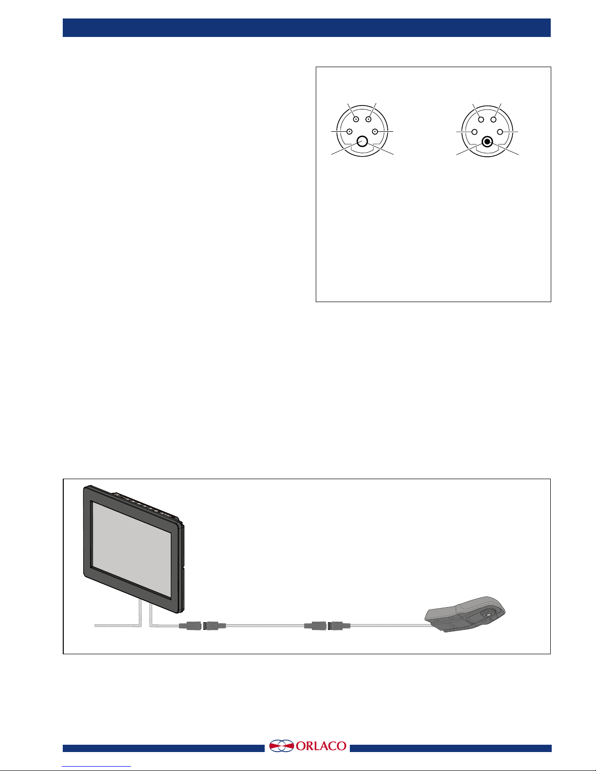
Connector/Cable: 0,5m cable with Coax and mold-
ed male connector (camera power input and video
output).
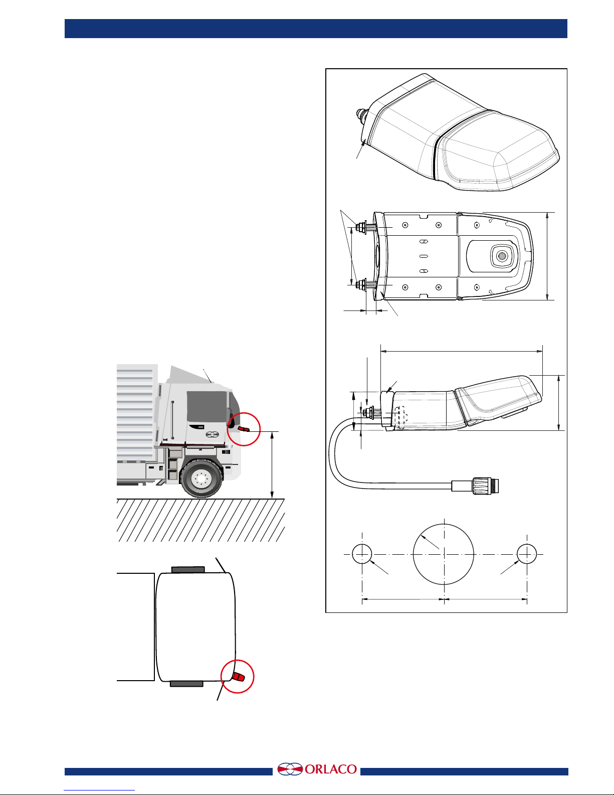
Min. cable bend radius: 50mm.
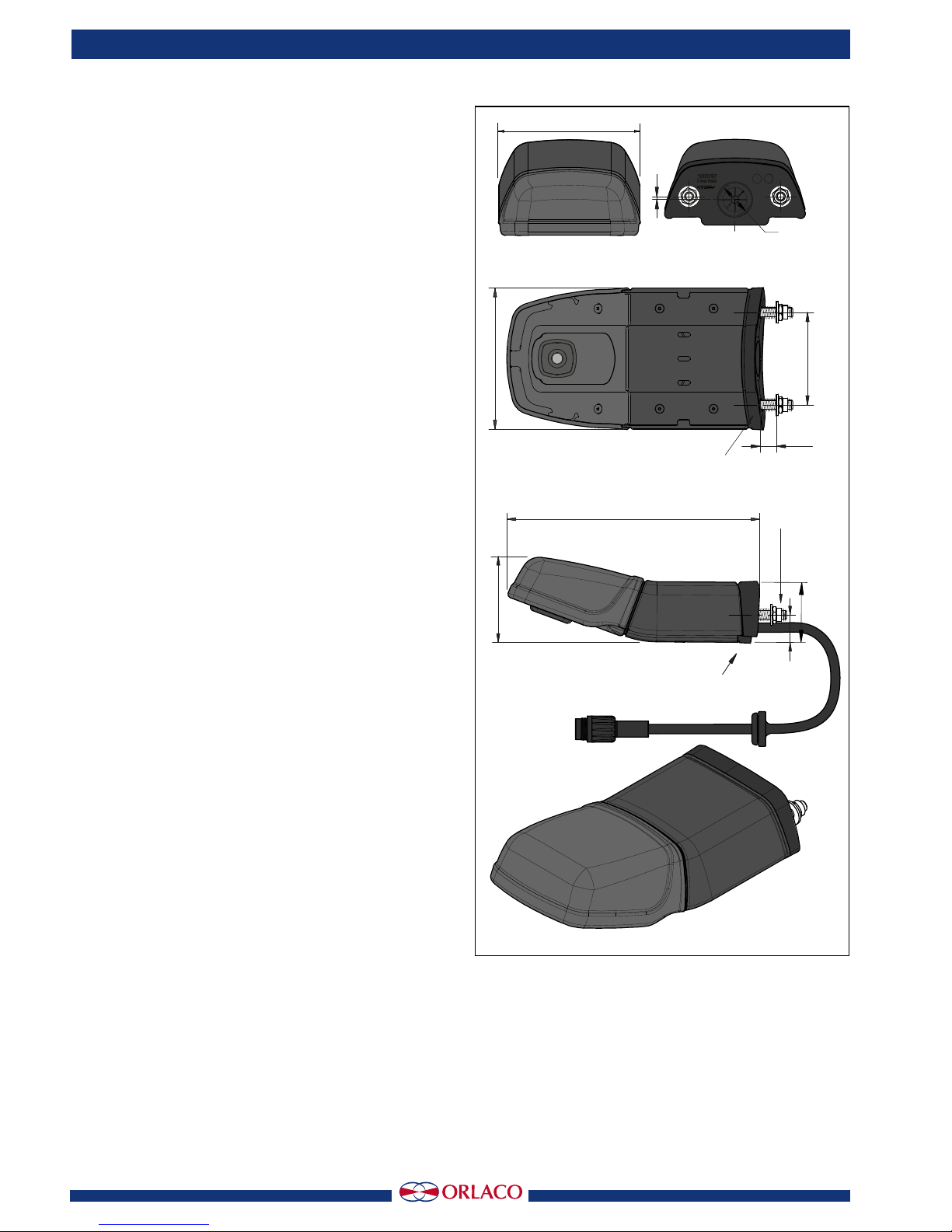
Mechanical
Housing: Anodised aluminium, black, UV resistant,
light fastness >8, corrosion proof according IEC
60068-2-52 salt mist, cyclic.
Filling: Camera is potted with automotive potting
resin.
Ingress protection: IP68 according to IEC 60529;
dust tight and protected against the effects of con-
tinuous immersion in water up to 10m under water
for 30 minutes. IP69k according to DIN 40050-9:
camera can withstand a high pressure cleaning
with water: 14-16L/min. 80°C and 100 bars flow.
Lens glass: Chemically hardened, toughed, tem-
pered float glass: 5 to 7 times stronger than ordi-
nary glass, protected against acid: class
2-3; DIN 12116, passed flying stone test.
Mounting hardware: Standard stainless steel.
Shock constancy: Shock and vibration resistant
for usage on trucks, cranes, fork-lifts, maritime
applications, machinery.
Camera bracket: Material: glass reinforced poly-
amide, test: 50 Nm at -40°C to +85°C.
Weight: 0,29kg. including cable, bracket and
mounting material. 0,48kg in sta ndard packing.
Truck use: Withstand all fluids and materials used
in and around trucks like: ammonia solution 5%,
ethanol 80-100%, isopropanol
5-10%, soapy water (min. 50% soap per volume),
alkaline degreasing compounds(used in high pres-
sure washing equipment).
Operating temperature: -40°C to +85°C.
Storage temperature: -40°C to +125°C.
Certication
Approvals in compliance with all relevant EMC-
and Automotive directives.
Certificates available upon request.
Compliant with RoHS and REACH.
Statement
This device complies with Part 15 of the FCC
Rules. Operation is subject to the following
conditions: (1) this device may not cause harmful
interference, and (2) this device must accept any
interference received, including interference that
may cause undesired operation.

Installation manual
8
IM0973520 A 04
Figure 7
Front view Back view
Side view
Bottom view
Units in mm.
91,2
168
2
60
92
∅20
Max 10
40
56
19
Extension
Extension
M6 (2x)
Max torque 6Nm
6. Dimensions
See figure 7.
7. General terms and conditions
Orlaco Products BV is not liable for damage re-
sulting from inadequate servicing, incorrect usage
or alterations made to the equipment without
informing the manufacturer in writing.
This installation manual has been made available
by Orlaco Products BV. All rights reserved. No part
of this manual may be reproduced and/or made
public in printed form, in photocopy form or on
microfilm, or in any other way, without the prior
written permission of Orlaco. This also applies to
the associated drawings and figures.
Orlaco reserves the right to make changes to com-
ponents at any time without informing customers
beforehand or directly. All dimensions given are for
commercial purposes.
For information regarding repairs that is not
covered in this manual, please contact the Orlaco
Products BV service department.
This manual has been prepared with all due care
and attention. However, Orlaco Products BV cannot
be held responsible for any errors in this manual
or any consequences thereof.

Installation manual
IM0973520 A 04
9
8. Available documentation
User Manual
UM0972220 Monitor 10” HLED
Installation Manual:
IM0973570 Camera HMOS
IM0973620 CornerEye®Set NCG PL+ CornerEye®Set PL + CornerEye® Set A-Pillar
IM0973580 Monitor HLED 10” 1
Data sheets
DS0960131-03110_ Cable *m Uni Digicoax
DS0961400-0185610 Set HMOS CornerEye®
DS0962201-0224000 Monitor 10” HLED 1
9. Release notes
R1-0 First issue, Dec 2014
R1-1 All parts changed, August 2015
R1-2 Bracket changed, October 2015
R1-3 Gasget rubber added, December 2015
R1-4 Field of vision R46 added, February 2016
A 01 FCC Statement added, December 2016
A 02 Extension bracket added, January 2017
A 03 Chapter 4 added, May 2017
A 04 Mounting rubber deleted, September 2017

Installation manual
10
IM0973520 A 04

Installation manual
IM0973520 A 04
11

ORLACO
Orlaco is a Manufacturing company that specializes in making cameras and
monitor systems for commercial vehicles, fork-lift trucks, cranes, off shore
and maritime.
Our objective is to design and produce camera systems for the professional
market that improve the drivers’ view and increase operating efficiency.
At our facility in Barneveld we locate our design, manufacturing, ware-
housing and service department.
Vision is our mission®. Orlaco therefore deploys the development, manu-
facture, supply and service of camera and display systems that will improve
safety and efficiency of all vehicles, machinery and vessels.
Our systems give the end user a view on each blind spot and will create
comfort and improved working conditions. Our active approach will support
market demands and innovations and will lead to enthusiastic ambassadors
in the market; our customers.
Table of contents
Other Orlaco Digital Camera manuals

Orlaco
Orlaco CCC User manual

Orlaco
Orlaco RadarEye User guide

Orlaco
Orlaco IM0973510 R1-2 User manual

Orlaco
Orlaco Camera EMOS Ethernet with Ex housing User manual

Orlaco
Orlaco HMOS User manual

Orlaco
Orlaco 0103481 User manual

Orlaco
Orlaco 0401432 User guide

Orlaco
Orlaco AFZ Sst User manual

Orlaco
Orlaco 0506972 User manual

Orlaco
Orlaco FAMOS User manual