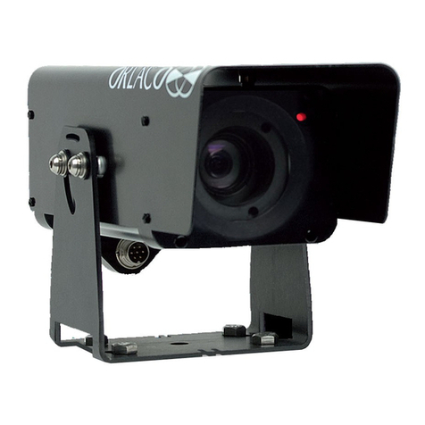
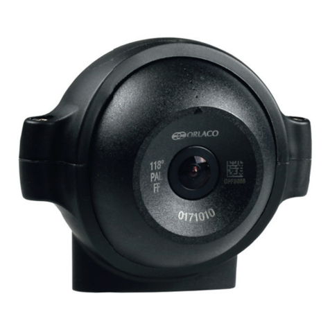
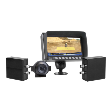
Orlaco IM0973510 R1-2 User manual

ORLACO
ORLACO PRODUCTS BV
Albert Plesmanstraat 42, 3772 MN Barneveld
PO Box 193, 3770 AD Barneveld
The Netherlands
Phone: +31 (0) 342 404555
E-mail: [email protected]
Internet: www.orlaco.com
Orlaco is a Manufacturing company that specializes in
making cameras and monitor systems for commercial
vehicles, fork-lift trucks, cranes, off shore and maritime.
Our objective is to design and produce camera systems for
the professional market that improve the drivers’ view and
increase operating efficiency.
At our facility in Barneveld we locate our design,
manufacturing, warehousing and service department.
Vision is our mission®. Orlaco therefore deploys the
development, manufacture, supply and service of camera
and display systems that will improve safety and efficiency
of all vehicles, machinery and vessels. Our systems give the end user a view on each blind
spot and will create comfort and improved working conditions. Our active approach will
support market demands and innovations and will lead to enthusiastic ambassadors in the
market; our customers.
For more information: www.orlaco.com
Camera FAMOS
Installation manual
Including specifications
No. IM0973510 R1-2
1/2015
English

IM0973510 R1-2
2
Before you start using this equipment, please read this manual carefully and
follow all instructions. We recommend that you keep this manual in a safe place
for reference purposes.
If you have any questions or issues concerning the operation of this equipment,
consult the relevant section in the manual or contact the Orlaco Products BV
Service department.
The camera/display systems from Orlaco comply with the latest CE, ADR, EMC
and mirror-directive regulations. All products are manufactured in accordance
with the ISO 9001 quality management, ISO/TS16949 quality automotive and
ISO 14001 environmental management.
Compact Camera
Type FAMOS PAL NTSC
Safety
In order to guarantee safe operation, these safety instructions must
be read before you start using this equipment.
• Do not open the enclosure. This can cause damage, short-circuiting or
electrical shocks.
• Do not expose the equipment to extreme temperatures. This can cause defor-
mation of the enclosure or damage to internal components.
• Repairs may only be undertaken by the manufacturer.
• The equipment must be assembled as shown in this manual.
Installation manual
11
Installation manual
5. Disposal
Disassembly, removal and disposal. Local regulations for dealing with waste
must be followed when disposing of disassembled components or entire units.
6. General terms and conditions
Orlaco Products BV is not liable for damage resulting from inadequate servicing,
incorrect usage or alterations made to the equipment without informing the
manufacturer in writing.
This installation manual has been made available by Orlaco Products BV.
All rights reserved. No part of this manual may be reproduced and/or made
public in printed form, in photocopy form or on microfilm, or in any other way,
without the prior written permission of Orlaco. This also applies to the associa-
ted drawings and figures.
Orlaco reserves the right to make changes to components at any time without
informing customers beforehand or directly. All dimensions given are for com-
mercial purposes.
For information regarding repairs that is not covered in this manual, please
contact the Orlaco Products BV service department.
This manual has been prepared with all due care and attention. However, Orlaco
Products BV cannot be held responsible for any errors in this manual or any
consequences thereof.
7. Revision details
R1-0. First issue, January 2015.
R1-1. Specifications changed, page 8, February 2015.
R1-2. Camera lenses(page 8) and Friction pad added(page 4), October 2015.
IM0973510 R1-2
10
Installation manual
Certication
Approvals:
Approvals in compliance with all relevant EMC- and Automotive directives.
This device complies with Part 15 of the FCC Rules. Operation is subject to the
following conditions: (1) this device may not cause harmful interference, and
(2) this device must accept any interference received, including interference that
may cause undesired operation. Certificates available upon request.
Green Passport:
All materials are compliant to Green Passportrequirements according
IMO resolution MEPC.197(62) as adopted on 15 July 2011 (Maritime
sector:International Maritime Organization concerning the functions of the
Marine Environment Protection Committee).
4. Maintenance and cleaning
Fixing a blurry image:
If the camera image is blurry, it is
advisable to clean the camera.
Cleaning the lens glass:
Use a soft cloth to clean the lens glass
of the camera. Use clean water or a
high quality and safe foam cleaner.
Rub the camera lens glass clean with
the cloth.
Do absolutely not use aggressive che-
micals or abrasive cleaning agents.
3
Contents page
1. Mounting and connecting Camera 4
1.1. Universal camera bracket 4
1.2. Camera attachment 4
1.3. Aiming the camera 5
1.4. Mounting the standard cable with molded connectors 5
1.5. Finish 6
2. Pin connection 6
3. Specifications 7
4. Maintenance and cleaning 10
5. Disposal 11
6. General terms and conditions 11
7. Revision details 11
Installation manual

IM0973510 R1-2
4
1. Mounting and connecting Camera
Overhead Horizontal
1.2. Camera attachment.
Recommendation:
The bracket should be tightened with a torque of 6 Nm nominal.
Tighten by hand or with very low speed.
1.1. Universal camera bracket.
ooa
Vertical Sloping surfaces
Installation manual
R
Min. bend radius (R) = 50mm
Units in mm
M6 x 20
6,5
25
55
19
9
Installation manual
Mechanical
Housing:
Cycoloy (PC + ABS). Filling: Camera is potted with Polyurethane elastomer.
Ingress protection:
IP68 according to IEC 60529; dust tight and protected against the effects of
continuous immersion in water up to 10m under water for 30 minutes. IP69k
according to DIN 40050-9: camera can withstand a high pressure cleaning with
water: 14-16L/min. 80°C and 100 bars flow.
Mounting hardware:
Standard stainless steel.
Shock constancy:
Shock and vibration resistant for usage on trucks, cranes, fork-lifts, maritime ap-
plications, machinery. Random vibration test 15,3Grms at frequency: 24 to 2000,
PSD (g²/Hz) 0,04 to 0,10.
Camera bracket:
Material: glass reinforced polyamide, test: 50 Nm at -40°C to +85°C.
Weight:
0,21kg, 0,29 in standard packing.
Truck use:
Withstand all fluids and materials used in and around trucks like: ammonia solu-
tion 5%, ethanol 80-100%, isopropanol 5-10%, soapy water (min. 50% soap per
volume), alkaline degreasing compounds(used in high pressure
washing equipment).
Operating temperature:
-40°C to +85°C.
Storage temperature:
-40°C to +125°C.

IM0973510 R1-2
8
Installation manual
Electrical
Power input:
12...24V/DC. Below 6V: camera is non functional. Between 7V heating element
automatically activated (20% capacity). At 8V the camera is fully functional and
the heating is at 40% of its capacity. At 12V the heating is at 100% capacity.
Between 12V and 33V camera and heating element are fully functional. Above
33V the overvoltage protection is activated and camera plus heating element
are switched off. This overvoltage-protection is deactivated below 32V. Power
Circuit is protected up to 80V/Dc. Outputs are Short Circuit Protected.
In all these above mentioned values; a tolerance of +/-10% is applied.
Power consumption:
Heating off: 1.1W at 12V, 1.2W at 24V;
Heating on: Max. power at 24V 0,15A = 3,6W. Max. power at 12V 0.28A = 3.4W.
Inrush current:
At 12V: 4.5A, 300us. At 24V: 12.0A, 300us.
Heater element:
2.4W max.
Transient protection:
Camera may be powered directly from 12V or 24V battery without additional
electrical protection since camera has an integrated circuit that protects the
camera against over- and undervoltage, spikes, ripples and load dumps.
Connectors:
0,5m cable with 4p molded male connector (camera power input and video
output).
Min. cable bend radius:
50mm.
5
0,5m 1.4. Camera with molded connectors
Mounting the standard cable with
molded connectors.
1.3. Aiming the camera.
Attach the top part and bottom part of
the bracket with the included M3 head
cap screws and tighten with a torque
of 0,8 Nm - 1Nm. Allen key included.
Top part bracket
Bottom part bracket
Allen key
Installation manual

IM0973510 R1-2
6
0,5m
19mm
rubber grommet
inside cabin
outside cabin
1.5. Finish.
Installation manual
2. Pin connection
1 = Coax core
2 = Coax screen
3 = Red
4 = White
Shielding
41
2
3
(Video signal)
(Video GND)
(12/24V/DC )
(0V)
Connected to Connector housing and
Camera housing
FAMOS
Front side of 4 pins male molded connector:
7
Installation manual
3. Specifications Camera FAMOS
20°/40°/60°/80°/102°/118°/129°/170° PAL/NTSC
Description
Lens specied Hor. lens angle Vert. lens angle
FAMOS 170° 170° 127°
FAMOS 129° 129° 97°
FAMOS 118° 118° 89°
FAMOS 102° 102° 72°
FAMOS 80° 80° 59°
FAMOS 60° 60° 44°
FAMOS 40° 40° 31°
FAMOS 20° 20° 15°
Sensor
Video signal:
PAL = 720(H)x576(V) 50fld/s. NTSC = 720(H)x480(V) 60fld/s. 1 Vtt composite
video into 75 Ohm.
Sensor element:
¼” CMOS digital image sensor. 640 H x 480 V.
Light sensitivity:
<0,05 Lux.
Dynamic Range:
80dB.
Table of contents
Other Orlaco Digital Camera manuals

Orlaco
Orlaco RadarEye User guide

Orlaco
Orlaco Set Camera HMOS CornerEye User manual

Orlaco
Orlaco HMOS User manual

Orlaco
Orlaco 0103481 User manual

Orlaco
Orlaco AMOS 118 ATVC PAL Mirror User manual

Orlaco
Orlaco 0401432 User guide

Orlaco
Orlaco FAMOS User manual

Orlaco
Orlaco Camera EMOS Ethernet with Ex housing User manual

Orlaco
Orlaco CCC User manual

Orlaco
Orlaco 0506972 User manual