Orlaco 0401432 User guide

Linde 115 &
OM Pimespo Thesi series
System Manual
Manual no. 0993650 A 01
01/2014
English
Set Article No. 0401432

2 SM0993650 A 01
System Manual
Camera-monitor systems on Linde 115 and
OM Pimespo Thesi series reachtrucks.
Article no. 0401432 A01
Safety
In order to guarantee safe operation, these safety instruc-
tions must be read before you start using this equipment.
• Do not open the enclosure. The camera and the P&T
enclosure are pressurised. This can cause damage, short-
circuiting or electrical shocks.
• Do not expose the equipment to extreme temperatures.
This can cause deformation of the enclosure or damage to
internal components.
• Repairs or adjustments to the equipment may only be
undertaken by Orlaco.
• The equipment must be assembled as shown in this
manual.
• If there have been alterations or changes to this equipment
that have not been specifically approved by Orlaco, use of
this equipment is not permitted.
Preface
Before you start using this equipment, please read this manual carefully
and follow all instructions. This installation manual describes the func-
tions of the equipment, outlines the connection options and explains how
to put the equipment into operation. We recommend that you keep this
manual in a safe place for reference purposes.
If you have any questions or issues concerning the operation of this
equipment, consult the relevant section in the manual or contact the
Orlaco Products BV Service department.
The camera and monitor systems from Orlaco comply with the latest CE,
ADR, EMC and mirror-directive regulations. All products are manufac-
tured in accordance with the ISO 9001 quality management, IATF 16949
quality automotive and ISO 14001 environmental management.
Contents
1. Introduction 3
2. Freelift cylinder 3
3. Top of mast 4
4. Traverse pulley 4
5. Installing the camera 6
6. Overview 7
Available documentation:
DS0963370-0403330 Pulley for cable
DS0963380-0403340 Springset
DS0963371-0404750 Pulley Conversion Kit
DS0961474-0198710 Camera CFMC AMOS 51° PAL
DS0962117-0208902 Monitor RLED 7” RC 4 CS
DS0960043-0301731 Mastcable 15m 4p molded
DS0960043-0304341 Mastcable 5m 4p molded
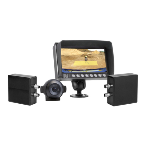
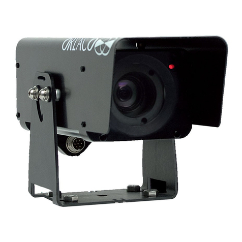
Fork view system for Linde 115/1120 series consists of:
0403330 Pulley for cable
0403340 Springset
0404750 Pulley Conversion Kit
0198710 Camera CFMC AMOS 51° PAL
0208902 Monitor RLED 7” RC 4 CS
0301731 Mastcable 15m 4p molded
0304341 Mastcable 5m 4p molded

SM0993650 A 01 3
System Manual
Camera-monitor systems on Linde 115 and
OM Pimespo Thesi series reachtrucks.
1. Introduction
The Linde 115 series reachtruck and the OM Pimespo Thesi
series reachtruck have a special mast design that is quite different from
any other reachtruck mast.
To install the mastcable in these masts, three pulley’s 0403330 and one
springset 0403340 are required. For a successful installation of these
pulley’s some additional mounting materials are required and these have
been assembled in the 0404750 Pulley Conversion Kit. See Fig. 1.
2. Freelift cylinder
On one of the pulley’s the M8x25 mounting bolt is removed from the
bracket and the center bolt is replaced by the M8x70 bolt. The original M8
spring washer and bolt are used to fix the pulley, the additional M8 nut
and the remaining M8 spring washer are placed on the bolt at approxi-
mately 15mm from the end as shown in fig. 2.
The axle of the hydraulic roll is drilled and tapped to a depth of approxi-
mately 10mm.
The pulley is then fixed to the axle as shown in figures 3 and 4.
Fig. 1: 0404750 Pulley conversion kit
Fig. 2: Modified pulley
Fig. 3: Placement of pulley Fig. 4: Placement of pulley
0403330 with parts of the Pulley Conversion Kit.
M8 x 25 remove
From original
pulley (043330)
Parts from 0404750
(Pulley Conversion Kit).
70.0
35.0
Important
Roll out the mastcable entirely to remove kinks
before installing it in the mast of the truck.

4 SM0993650 A 01
System Manual
3. Top of mast
The second pulley does not need to be modified and is installed hanging
from the traverse of the middle mast section as shown in figure 5.
Make sure that the pulley is placed in line with the chain and that the pulley does
not touch the forkcarriage.
4. Traverse pulley
The third pulley is installed standing on the traverse near the hydraulic’s
block. The traverse already has an M8 hole and this is used to fix the pul-
ley. In order to do this, the standard M8x25
mounting bolt is replaced by the M8x50 bolt and the pulley is fixed on the
traverse as shown in figure 6.
Two different mastcongurations can be found:
On the first mastconfiguration, the clearance between the traverse and
the next crossmember is very small. In order to fit, a second hole needs
to be drilled in the mounting bracket at 12 mm heart-distance below the
existing hole.
The pulley needs to be mounted in the lower hole as shown in figure 7.
As the clearance between the pulley and the crossmember above is only a
few millimeters it is not necessary to install the cable retainer.
Fig. 7: Traverse pulley, low clearance
Fig. 6: Placement of pulley
Fig. 5: Pulley in top of mast
Fig. A: Pulley in top of mast.
New hole
12mm below
existing hole
35.0
35.0

SM0993650 A 01 5
System Manual
Fig. 8: Traverse pulley, high clearance using strip
Fig. B: Traverse pulley, exploded view
Fig. 9: Traverse pulley cable retainer
Bracket from 0404750 (Pulley Conversion Kit)
is cut in half.
0403330 with adjusted Pulley Conversion Kit 0404750
Parts from 0404750
(Pulley Conversion Kit).
35.0
40.0
On the second mastconfiguration, the clearance between the traverse and
the next crossmember is larger.
The standard M8 x 35 centerbolt is replaced by an M8 x 40 bolt. This
allows the placement of the mounting strip which is made by cutting the
mounting bracket in half (see figure 8).
Using the additional M6 nut, the cable retainer is installed as shown in
figure 9.
Make sure that the white plastic cable retainer can turn freely.

6 SM0993650 A 01
System Manual
Fig. 10: Camera installed on fork
Fig. C: Cut position
Fig. 11: Mastcable fixed on backside of forkcarriage
Fig. 12: Springset on back of mast
5. Installing the camera system
The further installation is as follows:
The camera is installed on the inside of the right fork.
First the protective box section is angled so that the camera is parallel to
the fork, then it is fixed to the fork with 3 bolts as shown in figure 10.
Then the camera is inserted into the box section and both its mounting
holes are marked.
After these holes are drilled and tapped, the mastcable is guided through
the protective box section. The Female connector is fixed onto the cam-
era, and the camera is re-inserted into the tube and screwed to the fork.
The mastcable is fixed on the backside of the forkcarriage
between the tiltcylinders as shown in figure 11.
The clamps are installed by using the existing bolts in the forkcarriage.
A loop of cable allows for the movement of the sideshift
function. The cable is then guided over the pulley in the top of the mast,
then over the pulley on the freelift cylinder and finally over the pulley on
the traverse.
Then the springset is installed on the backside of the mast, and the cable
is fixed to it as shown in figure 12.
The cable is guided further by tie-wrapping it along the hydraulic hoses
down the mast, through the reachwagon and under the battery compart-
ment into the cabin, where it is connected to the monitor. The monitor’s
power wires are connected to the 48Vdc main power supply through a
fuse.
In case the mast needs to be removed for transportation after
installation of the camera system, a connectorset (1310850+1312050)
should be installed near the bottom of the mast to allow disconnection.
Important
Roll out the mastcable entirely to remove kinks
before installing it in the mast of the truck.
M6 x 10
320,0
15,5
20,0
30,0
23,0
2,0
70,0
93,5
188,5
284,5
25,0
∅4,0 ∅6,5
ORLACO
Ca m e r a - M o n i t o r Sy s t e m s
Model no.
Serial no.
Cut 23 mm and
bend approx. 90°
90°

SM0993650 A 01 7
System Manual
Fig. 13: Overview of mastcable routing
6. Overview of mastcable routing
Pulley on traverse
See page 4-5 Fig. 6 + 8
Pulley in
3th mast section
See page 4 Fig. 5
Fix spring set to
cross member
Modified Pully
on free lift cylinder
See page 3 Fig. 2
Fixation of cable on
the fork carriage
75
14

ORLACO
Orlaco is a Manufacturing company that specializes in making cameras
and monitor systems for commercial vehicles, fork-lift trucks, cranes, off
shore and maritime.
Our objective is to design and produce camera systems for the profes-
sional market that improve the drivers view and increase operating
efficiency.
At our factory in Barneveld, we have a production department, ware-
house, design department, service department and showroom.
Vision is our mission, and Orlaco therefore deploys the development,
manufacture, supply and service of camera and display systems that will
improve safety and efficiency of all vehicles, machinery and vessels. Our
systems give the end user a view on each blind spot and create comfort
and improved working conditions. Our active approach will support mar-
ket demands and innovations and will lead to enthusiastic ambassadors
in the market; our Customers.
Table of contents
Other Orlaco Digital Camera manuals

Orlaco
Orlaco AMOS 118 ATVC PAL Mirror User manual

Orlaco
Orlaco RadarEye User guide

Orlaco
Orlaco CCC User manual

Orlaco
Orlaco FAMOS User manual

Orlaco
Orlaco IM0973510 R1-2 User manual

Orlaco
Orlaco AFZ Sst User manual

Orlaco
Orlaco 0506972 User manual

Orlaco
Orlaco HMOS User manual

Orlaco
Orlaco 0103481 User manual

Orlaco
Orlaco Set Camera HMOS CornerEye User manual
Popular Digital Camera manuals by other brands

Panasonic
Panasonic LUMIX DMC-LC1EB operating instructions

Datacolor
Datacolor SpyderLENSCAL Manual guide

X-Loupe
X-Loupe Conceiver series MPG4 PLUS user guide

ARTRAY
ARTRAY ARTCAM-185IMX-HD3 Instruction booklet

Vivitar
Vivitar Vivicam 3712xi owner's manual

Canon
Canon EOS M EF-M 22mm STM Kit instruction manual