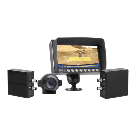
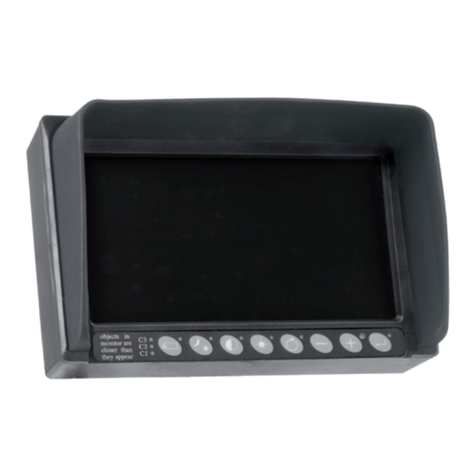
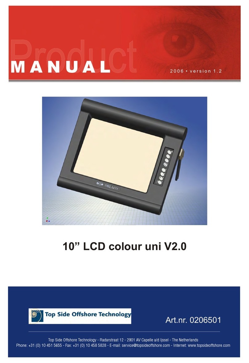
Orlaco ELED Ethernet User manual

Monitor 7” ELED
Standard Ethernet
BroadR-Reach
User manual
No. UM0972229 A 03
01/2021
English Monitor 7” ELED

2UM0972229 A 03
User Manual
Orlaco Monitor 7” ELED
Standard Ethernet, BroadR-Reach
Manual number UM0972229, Version A 03
Check at www.orlaco.com which language versions are available.
This manual contains user instructions. Used photographs and
illustrations give general information and may differ from the
products you use.
Contact your Orlaco dealer if you have questions, additional
information, or want to make changes that are not described in this
manual.
The camera and monitor systems from Orlaco comply with the
latest CE, ADR, EMC and mirror-directive regulations. All products
are manufactured in accordance with the ISO 9001 quality manage-
ment, IATF 16949 quality automotive and ISO 14001 environmental
management.
For installation Orlaco Monitor 7” ELED
see Manual IM0973576
Used abbreviations
ABC = Automatic Backlight Control
OSD = On Screen Display
HDR = High Dynamic Range
STND = Standard
LCD = Liquid Crystal Display
CAN = Controller Area Network
SRD = Short Range Device
T_T = Tacho-Turn
NIT = Night mode
TCH = Tachometer
Article numbers ORLACO Monitor 7” ELED
This manual describes the operating instructions of the following
ORLACO article numbers. The article numbers can be found on the
label on the back of the Monitors.
ELED Ethernet; Art. No. 0228000
ELED BroadR-Reach; Art. No. 0228020
Monitor 7” ELED;
User manual

3
UM0972229 A 03
Contents
Contents Page
1. Quick Reference 4
2. Getting Started 5
2.1. Disclaimer 5
2.2. Description of the Keyboard 5
2.3. Language setting for the OSD menu 5
2.4. New Camera detected menu 5
3. Using the service menu 6
3.1. Camera settings 6
3.1.1. Mirror 6
3.1.2. Upside down 6
3.1.3. Switch delay 6
3.1.4. Horizontal marker 6
3.1.5. Marker position 6
3.1.6. Vertical marker 6
3.1.7. Marker position 6
3.1.8. Graticule 6
3.1.9. HDR 7
3.1.10. Camera type 7
3.1.11. PIP Mode 7
3.1.12. PIP window settings 7
3.2. Camera tags 7
3.3. System settings 7
3.3.1. Language 7
3.3.2. On Screen Display (OSD) 7
3.3.3. Keyboard 8
3.3.4. CAN bus 8
3.3.5. LCD Backlight 8
3.3.6. Scanning 9
3.3.7. Camera switch 9
3.3.8. Front camera 9
3.3.9. Tacho settings 10
3.3.10. Default settings 10
3.3.11. Advanced 10
3.4. Info 11
4. System overview ELED 12
5. Overview of menus 13
6. Version details 14

4UM0972229 A 03
1. Quick Reference
Button 2
Option/previ-
ous menu
Button 3
Minus -
select/setting
Button 4
Plus +
select/setting
Button 5
Enter /
standby
Button 1
Camera
selection
Key 1, camera selection
Press the camera selection key once; manual camera selection is enabled. Use the
plus and minus keys to select the camera. Press the key again to disable manual
camera selection.
Key 2, option/previous menu
Return to the previous menu.
Key 3, minus
Go to the next menu option or move left.
Key 4, plus
Go to the previous menu option or move right.
Key 5, enter/standby
Switch to Standby or in the menus, select or activate the chosen option.
Keyboard
Below is a brief description of the key functions. See sections 3 and 4 for a more detailed explanation.
Button 1
Button 2 Button 3 Button 4 Button 5
Button 1
Button 2
Button 3 Button 4 Button 5
Button 1 Button 2
Button 3
Button 4 Button 5
Button 1 Button 2 Button 3
Button 4
Button 5
Button 1 Button 2 Button 3 Button 4
Button 5
Button 1 Button 2 Button 3 Button 4 Button 5

5
UM0972229 A 03
2.1. Disclaimer
When switching on the monitor for the first time, a disclaimer ap-
pears in English for 5 seconds (see Figure 1).
Displayed text: Do not operate display functions during safety criti-
cal operations. Objects in the monitor are closer than they appear. If
a different language is subsequently set, the disclaimer text appears
in the set language.
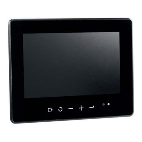
2.2. Description of the keyboard
Button no. 1 = Camera selection
Button no. 2 = Option/previous menu
Button no. 3 = Minus selection/setting key (-)
Button no. 4 = Plus selection/setting key (+)
Button no. 5 = Enter/Standby
2.3. Language setting for the OSD (On Screen Display)
menu
The OSD menu language is set as English by default. If you would
like to operate the OSD menu in a different language, open the
service menu → system settings. See section 3 on page 6. The
OSD menu is available in English, Dutch, German, French, Czech,
Hungarian, Italian, Polish, Portuguese, Spanish, Turkish, Swedish,
Finnish, Danish and Norwegian.
2.4. New camera detected menu
The “New camera detected” menu appears whenever a new camera
is recognized by the ELED (see figure 2). The MAC address of the
camera is displayed, and the user has to choose which camera
number this camera will receive. Each camera will show ‘In use’ if
it has been assigned, or ‘Free’ if no camera has been assigned. An
‘In use’ camera can be reassigned, the MAC address and camera
number will be overwritten with the new one.
If during the life time of the ELED you would like to reassign the
camera order, please refer to section 3.3.11, subsection Exchange
cameras.
Figure 1
Figure 2
2. Getting started
Keys
Button 1 Button 2 Button 3 Button 4 Button 5
1 2 3 4 5
6UM0972229 A 03
Figure 5
Figure 6
Figure 7
Figure 8
Figure 3
Figure 4
3. Service menu
3. Using the service menu
To open the service menu, simultaneously press the camera selec-
tion key (1), the minus key (3) and the plus key (4). The Service
menu (see Figure 3) will appear. The following keys are used to
navigate through the menus:
2 - Option/previous menu: Return to the previous menu
3 - Minus: Go to the next menu option
4 - Plus: Go to the previous menu option
5 - Enter: Select or enable the chosen option
3.1.
Camera settings
Select camera settings. Press enter to open the 'Camera
settings' menu.
Press enter again to activate the cursor in the list of
items. Use the minus (3) and plus (4) keys to select the
item to adjust and then confirm this selection by pressing
the enter key. If the selection is an on/off switch, you can
choose between on and off. If the selection is a number,
you can change the value using the minus (3) and plus (4) keys. Save
the new settings by pressing the enter key (5).
3.1.1. Mirror
Enable this option to mirror the image (reverse left and right).
3.1.2. Upside down
This option flips the image (upside down).
3.1.3 Switch delay
Enable this option if the switchwire is controlled by an intermittent
signal (e.g. from an indicator light).
3.1.4. Horizontal marker
Enable this option to show a reference line. The reference line is dis-
played as a horizontal green line.
3.1.5. Marker position
Adjusts the vertical height of the reference line. 0 corresponds to the
top edge of the monitor and 100 to the bottom edge.
3.1.6. Vertical marker
Enable this option to show a reference line. The reference line is dis-
played as a vertical green line.
3.1.7. Marker position
Adjusts the vertical position of the reference line. This can be set
between 0 and 100. 0 corresponds to the left side of the monitor and
100 to the right side. The left and right sides swap position depending
on the settings of the camera mirror-image function.
3.1.8. Graticule
This option shows a graticule for a rearview camera on the monitor.
3.1.9. HDR
Enable this option for the High Dynamic Range camera mode. Turn
on or off.
Keys
Button 1 Button 2 Button 3 Button 4 Button 5
1 2 3 4 5
7
UM0972229 A 03
Figure 9
3.1.10. Camera type
Select the connected camera type, which will also enable special
features applicable to the selected type.
3.1.11. PIP Mode
Set this option to ON to enable Picture In Picture, Split Screen,
horizontal/vertical or Quad mode.
3.1.12. PIP window settings
These menus have the following options:
W1, W2, W3, W4 Camera
Select wich camera should be shown in the PIP window.
W1, W2, W3, W4 Mirror
Set this option to “on” to mirror (exchange left/right) the PIP
window.
W1, W2, W3, W4 Flip
Set this option to “on” to flip (exchange top/bottom) the PIP
window.
3.2. Camera tags
See Figure 9. In this menu, names can be given to the camera
inputs.
3.3. System settings (see Figure 10)
3.3.1. Language
See Figure 11. This option opens the language selection menu. The
selected language will be used for all OSD menus. The OSD menu is
available in English, Dutch, German, French, Czech, Hungarian,
Italian, Polish, Portuguese, Spanish, Turkish, Swedish, Finnish,
Danish and Norwegian.
3.3.2. On Screen Display (OSD)
This option opens the OSD settings menu. See Figure 12.
The following can be set in this menu:
OSD time-out
Sets the time (in seconds) that the OSD (camera number/name,
top left) appears on the monitor. Select 'Off' to disable this and
'On' to have this permanently enabled.
OSD horizontal pos.
Adjust horizontal placement of the menu on the screen.
OSD vertical pos.
Adjust vertical placement of the menu on the screen.
OSD rotation
Adjust the rotation for the OSD so that it is legible when the
monitor is rotated.
Info transparency
Changes the transparency of the camera tag, etc.
Menu transparency
Changes the transparency of the menu system.
Figure 10
Figure 11
3. Service menu
Figure 14
Figure 13
Figure 12

8UM0972229 A 03
Figure 19
3. Service menu
Figure 18
Disclaimer transparency
Changes the transparency of the disclaimer when starting up.
Marker transparency
Changes the transparency of the horizontal and vertical markers.
Graticule transparency
Changes the transparency of the graticule (perspective overlay).
OSD menu help
This function enables or disables the automatic text messages
of the OSD help menus. If enabled, help messages automatically
appear in all menus after 10 seconds of inactivity.
3.3.3. Keyboard
This option opens the keyboard menu. See Figure 16.
Keyboard lock
This option opens the settings menu for the keyboard lock. It
is possible to lock various functions in order to prevent any
unwanted changes. See Figure 17.
Keyboard sound
Turn the keyboard sound on and off.
Beeper volume
Set the volume of the keybourd and/or alarm beeper.
Standby mode
Choose the way you want to enter standby mode.
3.3.4. CAN bus
See Figure 18. This option opens the CAN bus menu. This menu
has the following 5 options:
CAN protocol
This option selects the signal, or CAN protocol, that the Monitor
uses. By default this is Orlaco CAN protocol 1. Other protocols
are customer-specific. The CAN speed is automatically adjusted,
but it can also be set manually once the protocol has been
selected.
CAN speed
This option selects the bit rate of the CAN bus. Available options
are: 100, 125, 200, 250, 500 and 1000 kbit.
Set CAN-ID
The Orlaco CAN protocol has an ID (default 0) to control multiple
monitors via one CAN bus. The ID is inactive when the text is
blue and becomes active when the protocol is set to 1. The CAN-
ID can be set from 0-15 where 0 is the default value.
Terminator
Enable/disable the 120 Ω terminator on CAN communications port
3.3.5. LCD backlight
This option opens the backlight submenu for the Monitor 7” ELED.
See Figure 19. This menu has the following 3 options:
Figure 16
Figure 17
Figure 15

9
UM0972229 A 03
Figure 20
Figure 21
LCD backlight mode
This option enables automatic backlight control (ABC). The Moni-
tor automatically adapts its brightness to the ambient light. If
required, a specific day or night brightness can be manually set.
Alternatively, the user can choose to manually adjust the day or
night brightness setting.
ABC = Standard Automatic Brightness Control
DAY = Day mode (can be adjusted between 50–100%)
NIT = Night mode (can be adjusted between 0–50%)
ABC minimum level
This setting determines the minimum brightness the ABC can use
when there is low ambient light.
LCD backlight day
This option allows the day brightness setting to be manually
adjusted (50–100%).
LCD backlight night
This option allows the night brightness setting to be manually
adjusted (0–50%).
3.3.6. Scanning
This option opens the camera scanning submenu. See Figure 20.
This menu has the following options:
Scan sequence
This option selects the cameras from which images are to be
shown in sequence.
Scan interval
This option selects how long a camera image is displayed.
3.3.7. Camera switch
Select how many cameras will be connected to the ELED moni-
tor; options: 1c to 6c.
3.3.8. Front camera
This option opens the front camera submenu for the ELED 7” monitor.
This enables the front camera functionality (a statutory obligation). See
figure 16.
Enable frontcam
Enable this option when a frontcam is connected.
Invert handbrake
Enable this option if the handbrake signal on the yellow wire is
inverted.
Pulses per meter
Set this value to the amount of pulses the tachometers generates
per meter. (0 - 250).
Function AUX wire
Defines the function of the AUX1 & AUX2 switching wires (grey
and yellow). Select TCH for the tachometer function (Tacho to
AUX1). Select KEY for + and - key functions on AUX1/2.
3. Service menu
Figure 22

10 UM0972229 A 03
Figure 25
Figure 26
Figure 27
3.3.9. Tacho settings see figure 24.
Settings related to switching a camera based on tacho speed:
AUX wire function:
Select the function of the AUX1 and AUX2 wires.
OFF - AUX wires no function.
TCH - for the tachometer.
KEY - for + and - key functions on AUX1/2.
C-+ - Aux wires open = activate Cam 1 or Monitor standby.
Aux wire 1 = activate Cam toggle up 1 to 4.
Aux wire 2 = activate Cam toggle down 1 to 4.
T_T - Tacho-Turn, setting for the Orlaco Side-eye system.
The AUX1 wire is connected to the Tacho signal and
the AUX2 wire to the right turn flashing light signal.
Pulses per meter
Set this value to the amount of pulses the tachometers generates
per meter. (0 - 250).
Cam to activate
Select which camera should be activated when tacho speed is
within selected range. (C1 - C6).
Cam on if speed >= (0 - 130)
Tacho low limit, Camera not activated when tacho < low limit.
.... and speed < (0 - 130)
Tacho high limit, Camera not activated when tacho > high limit.
Both menus Cam if speed >= and .. and speed < are connected;
Camera activated when tacho >= low limit and tacho < high limit.
The 2 conditions together must be active to switch the camera.
3.3.10. Default settings
See figure 25. This option opens the menu to restore the factory
default settings. Select the number of the factory settings that you
require (1 = default Orlaco settings).
Contact ORLACO for further information. Select the option ‘Restore
defaults’ to restore the factory settings. See figure 25.
3.3.11. Advanced See figure 26
System frame rate
Set the system frame rate to 25/30Hz or 50/60 Hz depending on
the power frequency used. This prevents flicker from TL and HID
lights.
Camera mbit rate
Choose which mbit rate the cameras should be set.
Set DHCP/WISR mode
Enable the build-in DHCP server to automatically assign IP address-
es or allow a WISR (Art. No. 0300100) host to handle that task.
Display number
Assign a display number to this display to enable the use of multiple
display on the same ethernet segment. Turn monitor off and on for
this to take effect.
3. Service menu
Figure 23
Figure 24

11
UM0972229 A 03
Figure 28
Figure 29
Exchange cameras
Exchange camera numbers. After the exchanges, the system
needs to be power cycled to start new camera recognition and as-
signment process for the changed cameras. See figures 28, 29.
Clear MAC addresses
Clear all MAC to camera assignments. The system needs to be
power cycled to start new camera recognition and assignment
process.
3.4. Info
This user manual describes the functions of the software version
indicated on this monitor.

12 UM0972229 A 03
1 camera system
4. System overview ELED
Power
Monitor 7” ELED
Monitor 7” ELED
Power
Switcher
Camera 1
Camera 2
Camera 3
Camera 4
Camera
Power
Power
Power
Power
Power
Power
2-4 camera system
Please pay attention that you use either Fast Ethernet or BroadR-Reach components in your system confi-
guration. You can not mix these components.
Note that Orlaco does not offer a BroadR-Reach switch. Our Fast Ethernet switch is Art. Nr. 0405440.

13
UM0972229 A 03
Service menu
Camera- + Minus- and Plus buttons
1, 2, 3, 4
Service menu
Camera settings
Camera tags
System settings
Info
Mirror, Upside down, Switch delay, Hor. marker, Marker pos. Vert. marker, Marker pos., Graticule, HDR, Camera type, PIP mode,
w1 camera, w1 Mirror, w1 Flip, w2 camera, w2 Mirror, w2 Flip, w3 camera, w3 Mirror, w3 Flip, w4 camera, w4 Mirror, w4 Flip,
System settings
Language
On screen display
Keyboard
CAN-bus
LCD-Backlight
Scanning
Camera switch
Frontcam
Tacho settings
Default settings
Advanced
ON, OFF, 30sec, 10sec, 3sec
1 - 28
1 - 100
1 - 28
1 - 100
1 - 28
0, 90, 180, 270
1 - 28
1 - 28
ON/OFF
1M, 500, 250, 200, 125, 100
0 - 15
On screen display
OSD timeout
OSD horizontal pos.
OSD vertical pos.
OSD rotation
Info transparency
Menu transparency
Disclaimer transp.
Marker tranparency
Graticule transp.
OSD menu help
Keyboard
Keyboard lock
Keyboard sound
Beeper volume
Standby mode
CAN-bus
CAN-protocol
CAN-speed
Set CAN-ID
Terminator
OFF, 1-8 positions
ON/OFF
ON/OFF
0-50
ON/OFF
ABC, NIT, DAY
ON/OFF
50-100
ON/OFF
0-50
Keyboard lock
Standby menu
Camera switch
Camera settings
Standby
LCD-backlight
LCD-backlight mode
ABC Minimum level
LCD-backlight day
LCD-backlight night
0 - 250
OFF, TCH, KEY,
C-+, T_T
1-30
25, 30, 50, 60
10m, 20m, 30m, 40m, 50m, 60m, 70m, 80m
DHC, WSR, OFF
1, 2, 3, 4
C1 - C6
0 - 130
0 - 130
Default settings
Select defaults
Restore defaults
Advanced
System frame rate
Camera mbit rate
Set DHCP/WISR mode
Display number
Exchange cameras
Clear MAC addresses
Tacho Settings
AUX wire function
Pulses per meter
Cam to activate
Cam on if speed >=
... and speed <
English, Dutch, German, French, Czech, Hungarian,
Italian, Polish, Portuguese, Spanish, Turkish, Swedish, Finnish, Danish and Norwegian.
2s, 5s, 10s
OFF, 12, 123, 1-4, 1-5
Scanning
Scan sequence
Scan interval
1c, 2c, 3c, 4c, 5c, 6c
ON/OFF
OFF 1c, 2c, 3c
0-250
OFF, TCH, KEY,
C+-, T_T
Frontcam
Enable Frontcam
Invert handbrake
Pulses per meter
AUX wire function
OFF KEY, ALM, K+A
0 - 100
MNU, IMM, 2s
Exchange cameras
Exchange cam 1 with C1
Exchange cam 2 with C2
Exchange cam 3 with C3
Exchange cam 4 with C4
Exchange cam 5 with C5
Exchange cam 6 with C6
ON/OFF
5. Overview of menus

14 UM0972229 A 03
6. Version details
Version A 01. First issue, January 2021.
Version A 02. Multiple changes, February 2021.
Version A 03. Article numbers deleted, March 2021.

www.orlaco.com
Orlaco is a Manufacturing company that specializes in making cameras and
monitor systems for commercial vehicles, fork-lift trucks, cranes, off shore
and maritime.
Our objective is to design and produce camera systems for the professional
market that improve the drivers’ view and increase operating efficiency.
At our facility in Barneveld we locate our design, manufacturing, warehousing
and service department.
Vision is our mission®. Orlaco therefore deploys the development, manufac-
ture, supply and service of camera and Monitor systems that will improve
safety and efficiency of all vehicles, machinery and vessels. Our systems
give the end user a view on each blind spot and will create comfort and
improved working conditions. Our active approach will support market
demands and innovations and will lead to enthusiastic ambassadors in the
market; our customers.
For more information: www.orlaco.com
ORLACO
This manual suits for next models
3
Table of contents
Other Orlaco Monitor manuals

Orlaco
Orlaco RLED CAN RB 4D CS User manual

Orlaco
Orlaco RadarEye User manual

Orlaco
Orlaco 0208203 User manual

Orlaco
Orlaco UM0972225 A 01 User manual

Orlaco
Orlaco RLED User manual

Orlaco
Orlaco HLED 1 User manual

Orlaco
Orlaco 0208500 User manual

Orlaco
Orlaco 0206501 User manual

Orlaco
Orlaco 0224000 User manual

Orlaco
Orlaco RLED User manual