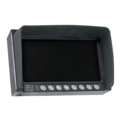
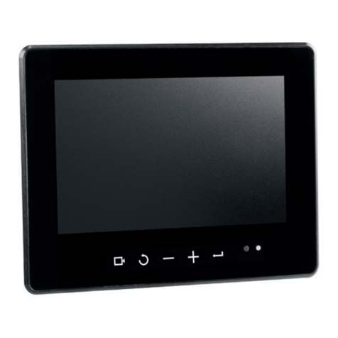
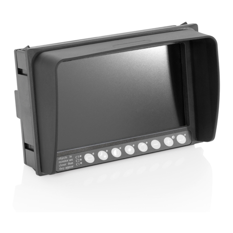
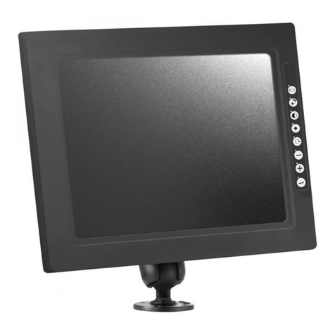
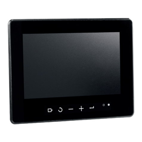
Orlaco HLED 1 User manual

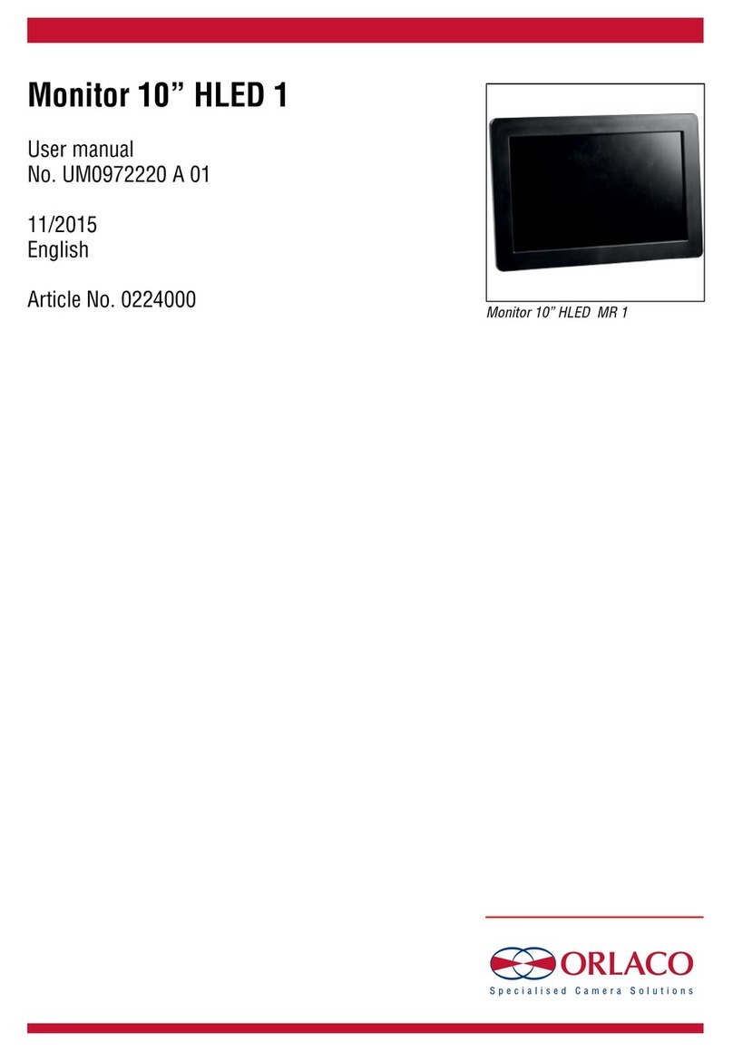
Monitor 10” HLED 1
Monitor 10” HLED MR 1
Installation manual
Manual No. IM0973580 A 04
11/2015
English
Article number: 0224000
0224010

2
IM0973580 A 04
Safety
In order to guarantee safe operation, these safety
instructions must be read before you start using
this equipment.
• Do not open the enclosure. This can cause
damage, short-circuiting or electrical shocks.
• Do not expose the equipment to extreme
temperatures. This can cause deformation of the
enclosure or damage to internal components.
• Repairs may only be made by the
manufacturer.
• The equipment must be installed as shown in
this manual.
Before you start using this equipment, please read this manual
carefully and follow all instructions. This System manual
describes the installation of the equipment, outlines the
connection options and explains how to put the equipment into
operation. We recommend that you keep this manual in a safe
place for reference purposes.
If you have any questions or issues concerning the operation
of this equipment, consult the relevant section in the manual or
contact the Orlaco Products BV Service department.
The camera and monitor systems from Orlaco comply with the
latest CE, ADR, EMC and mirror-directive regulations. All products
are manufactured in accordance with the ISO 9001 quality manage-
ment, ISO/TS16949 quality automotive and ISO 14001 environ-
mental management.
See User Manual UM0972220/UM0972223 for user instructions.
Contents page
1. Monitor variants 3
2. Monitor placement 3
3. Basic system installations 4
3.1. EMC 5
4. Technical specifications 6
5. Assembly, connection and data Monitor 10” 7
6. Maintenance and cleaning 9
7. Disposal 9
8. General terms and conditions 9
9. Release notes 10
Monitor 10’’ HLED 1, MR 1
Installation manual
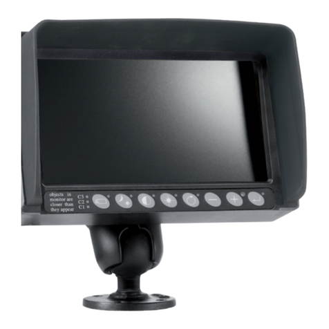
Keyboard Monitor 10” HLED 1, MR 1
Art. no. 0224000; Monitor 10” HLED 1
Art. no. 0224010; Monitor 10” HLED MR 1
3
IM0973580 A 04
Installation manual
1. HLED variants
HLED Art. No. Video Cable
Bracket
Power Cable
Page
Monitor 10” HLED 1 1
0224000 1 metre 4 pin female + Coax 1 metre 7
Monitor 10” HLED MR1
R
1
0224010 1 metre 4 pin female + Coax
Adjustable bracket 127mm
1 metre 8
2. Monitor placement (guideline)
The correct placement of the monitor depends on the type of the vehicle.
Please take note of the following guidelines when installing the monitor.
Obstruction of the eld of vision
The monitor must be placed in such a way that the field of vision of
surrounding traffic and the work area is obstructed as little as possible.
Obstruction of the operation
The monitor may not obstruct the basic operation within the vehicle.
View point on the monitor
Posture
View point on the monitor
Viewing direction of the monitor
Bad
Good Moderate
0° 15° 30°
Bad
Good
Moderate
0°
10°
20°
15°
0°
30°
15°
30°
Good
Good
Moderate
Moderate
Bad
Bad
Moderate (incidental)
0°
40°
Bad
Good
Bad (continual)
40 cm 75 cm
150 cm
Moderate Bad
Bad Good
Bad
Good Moderate
0° 15° 30°
Bad
Good
Moderate
0°
10°
20°
15°
0°
30°
15°
30°
Good
Good
Moderate
Moderate
Bad
Bad
Moderate (incidental)
0°
40°
Bad
Good
Bad (continual)
40 cm 75 cm
150 cm
Moderate Bad
Bad Good
Bad
Good Moderate
0° 15° 30°
Bad
Good
Moderate
0°
10°
20°
15°
0°
30°
15°
30°
Good
Good
Moderate
Moderate
Bad
Bad
Moderate (incidental)
0°
40°
Bad
Good
Bad (continual)
40 cm 75 cm
150 cm
Moderate Bad
Bad Good
Bad
Good Moderate
0° 15° 30°
Bad
Good
Moderate
0°
10°
20°
15°
0°
30°
15°
30°
Good
Good
Moderate
Moderate
Bad
Bad
Moderate (incidental)
0°
40°
Bad
Good
Bad (continual)
40 cm 75 cm
150 cm
Moderate Bad
Bad Good

4
IM0973580 A 04
3. Basic system installation
Power
Monitor 10” HLED MR 1
Art. No. 0224010
Monitor 10” HLED MR 1
Art. No. 0224010
Cable Uni DigiCoax
Camera HMOS
with bracket
Power
Cable DigiCoax
Cable DigiCoax
Cable DigiCoax
Cable DigiCoax
DigiCoax Switcher
Art. No. 0404240
4x
HMOS Camera
with bracket
Camera 1
Camera 2
Camera 3
Camera 4
Installation manual
1 Camera system
4 Camera system

5
IM0973580 A 04
3.1. Electromagnetic compatibility installation instructions (EMC).
Preferred installation
Installation especially for forklifttrucks.
Warning! On vehicles with separated powerwiring like electrical forklifttrucks no other installation is allowed,
the screening may NOT in any way be connected to the battery:
Color/wire Function Vehicle connection:
Red wire +(plus) power supply +(plus) voltage of the vehicle
(10..30V/Dc, 5A fuse)
White wire -(minus) GND power supply -(minus) of the vehicle
Screening powercable Eliminates EMC disturbances Chassis of the vehicle
Alternative installation
If no separate 0V/minus is available on the vehicle and the minus of the battery is connected to the chassis of the
vehicle; connection is as follows:
Color/wire Function Vehicle connection:
Red wire +(plus) power supply +(plus) voltage of the vehicle
(10..30V/DC, 5A fuse)
White wire and
Screening powercable
-(minus) GND power supply
and EMC
Chassis of the vehicle combined
with -(minus) of the vehicle
Preferred installation
Red wire
+ (Plus)
Power supply White wire
-(Minus) GND
Screening
To +(Plus) voltage
of the vehicle
To - (Minus)
of the vehicle
Red wire
+ (Plus)
Power supply
White wire
-(Minus) GND
Screening
To the chassis
and -(Minus)
of the vehicle
Alternative installation To +(Plus) voltage
of the vehicle
Connect screening to the chassis
and -(Minus) of the vehicle. Wire not included.
Connect screening to the chassis of the vehicle. Wire not included.
Installation manual

6
IM0973580 A 04
General
Type
10,1inch TFT LCD module with a white LED backlight.
Resolution
WXGA 1280 x RGB x 800 pixels.
Active Area
216.96 (H) x 135.60 (V) (10.1” diagonal).
Driver element
a-Si TFT active matrix.
Softwaremenu
Full On-Screen-Display (OSD) functionality in 13 languages.
ABC mode
Improved Auto Brightness Control (ABC) including one-touch day/night setting and adjustable minimum and maximum levels
for automatic control.
Operating temperature
-40°C...+85°C.
Electrical
Input voltage range
12V/24V/DC
Power consumption
12W@24V.
Protection:
Above 33V overvoltage protection, protection deactivated below 30V.
Below 7V undervoltage protection, protection deactivated above 8V.
Protected against load dumps, spikes and surges, reverse polarity on all wiring.
Power-output:
For powering camera. Output current 1A max. Power output is input voltage, protected against load dumps, spikes, surges and
reverse polarity.
Video input
Coax GMSL.
Mechanical
Surface
Hard coating (3H), with AG LR (Low Reflection) polarizer.
Housing
Color Black, material: high impact automotive synthetic thermoplastic polymer.
Protection
IP54 according IEC60529.
Temperature/humidity test
According IEC60068-2-1/2/3/14/30/38.
Certication
Quality & environment
Units are manufactured by Orlaco in the Netherlands; ISO 9001, ISO14001, ISO/TS 16949.
4. Technical specications
Installation manual

7
IM0973580 A 04
5. Assembly, connection and data Monitor 10” HLED 1
Connect instructions: Please refer to your Orlaco system documentation or chapter 3. “Basic System Installations”
User instructions: Please refer to User manual no: UM0972220 for operation.
Article No. 0224000 Monitor 10” HLED 1
Power cable open wired (Secure the power input with a 5A fuse)
1 = Red = Video power in: 12V/24V
2 = Blue = Aux 1
3 = Brown = Aux 2
4 = White = Power 0V in
5 = Grey = CAN-H
6 = Yellow = CAN-L
7 = White/yellow = N.C.
Video cable front side molded 4p + Coax female connector:
1 = Black = 0V
2 = Red = Power
3 = Yellow = Aux 1
4 = Grey = Aux 2
5 = Coax core = Video
6 = Coax shield = Video GND
Shielding = To housing
1
2
3
7
456
1
6
4
5
3
2
units in mm Min. bend radius= 50mm
R = 50
251
37,5
13,5
173
Video cable
Length 1m
Power cable
Length 1m
100
100
30
35,2
M5 (8x)
40
Connector Female
Molded M16 4p + coax
Cables / Connectors 1m multicable (power) open wired, 1m multicable (video) with 4p + Coax molded female connector
Weight
0,82kg (Monitor, cables and connectors)
Installation manual

8
IM0973580 A 04
Installation manual
Connect instructions: Please refer to your Orlaco system documentation or chapter 3. “Basic System Installations”
User instructions: Please refer to User manual no: UM0972220 for operation.
Article No. 0224010 Monitor 10” HLED MR1
Power cable open wired (Secure the power input with a 5A fuse)
1 = Red = Video power in: 12V/24V
2 = Blue = Aux 1
3 = Brown = Aux 2
4 = White = Power 0V in
5 = Grey = CAN-H
6 = Yellow = CAN-L
7 = White/yellow = N.C.
Video cable front side molded 4p + Coax female connector:
1 = Black = 0V
2 = Red = Power
3 = Yellow = Aux 1
4 = Grey = Aux 2
5 = Coax core = Video
6 = Coax shield = Video GND
Shielding = To housing
1
2
3
7
456
1
6
4
5
3
2
units in mm Min. bend radius= 50mm
R = 50
251
37,5
13,5
173
Video cable
Length 1m
Power cable
Length 1m
100
100
30
35,2
M5 (8x)
40
Connector Female
Molded M16 4p + coax
40,5
∅64,5
∅7 (4x)
Adjustable bracket
Cables / Connectors 1m multicable (power) open wired, 1m multicable (video) with 4p + Coax molded female connector
Bracket A clamping user-adaptable mounting bracket is supplied, Art. no. 0401290
Weight
0,82kg (Monitor, cables and connectors)

9
IM0973580 A 04
Installation manual
6. Maintenance and cleaning
First, do not touch the screen with your fingers. The underlying
transistors will react to the static electricity in your fingers, or may
get damaged by the pressure thus exerted. This will eventually
produce dead pixels; tiny, inoperative, or colored dots impairing
picture quality.
So take care when cleaning your delicate LCD Screen. Use a high
quality and safe foam cleaner and a soft cloth. Do absolutely not
use aggressive chemicals or abrasive cleaning agents.
7. Disposal
Disassembly, removal and disposal. Local regulations for dealing
with waste must be followed when disposing of disassembled
components or entire units.
8. General terms and conditions
Orlaco Products BV is not liable for damage resulting from
inadequate servicing, incorrect usage or alterations made to the
equipment without informing the manufacturer in writing.
This System manual has been made available by Orlaco
Products BV. All rights reserved. No part of this manual may be
reproduced and/or made public in printed form, in photocopy
form or on microfilm, or in any other way, without the prior
written permission of Orlaco. This also applies to the associated
drawings and figures.
Orlaco reserves the right to make changes to components at any
time without informing customers beforehand or directly. All
dimensions given are for commercial purposes.
For information regarding repairs that is not covered in this
manual, please contact the Orlaco Products BV service department.
This manual has been prepared with all due care and attention.
However, Orlaco Products BV cannot be held responsible for any
errors in this manual or any consequences thereof.

10
IM0973580 A 04
Installation manual
9. Release notes
R1-0. First issue, November 2015.
R1-1. Article number changed, December 2015.
R1-2. Cable length changed, February 2016.
R1-3. Article name changed, March 2016.
R1-4. Specifications: IP67 Changed to IP54, April 2016.
A 01. Article name changed, February 2017.
A 02. Monitor added, May 2017.
A 03. Chapter Switch wires added, October 2017.
A 04. Chapter 3 drawing added, chapter 6 removed, December 2017.

11
IM0973580 A 04
Installation manual

ORLACO
Orlaco is a Manufacturing company that specializes in making
cameras and monitor systems for commercial vehicles, fork-lift
trucks, cranes, off shore and maritime.
Our objective is to design and produce camera systems for the
professional market that improve the drivers’ view and increase
operating efficiency.
At our facility in Barneveld we locate our design, manufacturing,
warehousing and service department.
Vision is our mission®. Orlaco therefore deploys the development,
manufacture, supply and service of camera and display systems
that will improve safety and efficiency of all vehicles,
machinery and vessels. Our systems give the end user a view on
each blind spot and will create comfort and improved working
conditions. Our active approach will support market demands and
innovations and will lead to enthusiastic ambassadors in the
market; our customers.
This manual suits for next models
1
Table of contents
Other Orlaco Monitor manuals

Orlaco
Orlaco UM0972225 A 01 User manual

Orlaco
Orlaco RLED User manual

Orlaco
Orlaco RadarEye User manual

Orlaco
Orlaco ELED Ethernet User manual

Orlaco
Orlaco 0208500 User manual

Orlaco
Orlaco 0206501 User manual

Orlaco
Orlaco 0224000 User manual

Orlaco
Orlaco RLED User manual

Orlaco
Orlaco RLED CAN RB 4D CS User manual

Orlaco
Orlaco 0208203 User manual