Osaka PRO 08D User manual

QQUUIICCKK RREEFFEERREENNCCEE GGUUIIDDEE PPRROO 0088DD

Quick reference guide PRO 08D
Page 2 / 13
1. WARNING
WARNING: TO PREVENT FIRE OR ELECTRIC SHOCK, DO NOT EXPOSE THIS
APPLIANCE TO RAIN OR MOISTURE.
CAUTION: TO REDUCE THE RISK OF ELECTRIC SHOCK,
DO NOT REMOVE COVER (OR BACK). NO USER-
SERVICEABLE PARTS INSIDE, REFER SERVICING TO
QUALIFIED SERVICE PERSONNEL.
WARNING:
2VDND6ROXWLRQV6/ can accept no responsibility for any possible damage due
WKHXVDJHof not supported modems.
2VDND6ROXWLRQV6/ reserves itself the right to modify this manual without
QRWLFH
WARNING:
This quick reference guide is part of the product and should be kept near the
instrument to easy and quick reference. The instrument shall not be used for
different purpose from those described in this manual. It cannot be used as a
safety device. Check the application limits before proceeding.
WARNING:
Check the supply voltage is correct before connecting the instrument.
Do not expose to water or moisture: use the controller only within the operating
limits avoiding sudden temperature changes with high atmospheric humidity to
prevent formation of condensation.
Warning: disconnect all electrical connections before any kind of maintenance.
Fit the probe where it is not accessible by the End User.
The instrument must not be opened.
Consider the maximum current which can be applied to each relay (see
Technical Data).
Ensure that the wires for the probes, loads and the power supply are separated
and far enough from each other, without crossing or intertwining.
In case of applications in industrial environments, the use of mains filters (our
mod. FT1) in parallel with inductive loads could be useful.
OSAKA reserves the right to modify or change its products without prior warning.

2. Inputs and outputs – Basic configurations
CARATTERISTICHE - FEATURES PRO 08D
Alimentazione - Power supply
24 Vac/dc TF20 (24)
0÷1V - 0÷5V - 0÷10V - 0÷20mA
Ingressi sonde - Probe inputs
4÷20mA - NTC - PTC - DI
Opto-isolati - Opto-insulated
- contatti liberi/free contacts
Ingressi digitali - Digital inputs
11 config
Non disponibile
Not available
- contatti in tensione/power supply voltage contacts
(24Vac\dc)
Uscite relè - Relay outputs
Configurabili - Configurable
8
- Relè da 5A - Relay 5A (250Vac)
8 x PRO 08D
- Relè da 8A - Relay 8A (250Vac)
PWM per moduli ventole - PWM outputs fan speed module
Altre uscite - Other outputs
Non disponibile
Not available
Non disponibile
Not available
0÷10V - 4÷20mA per mod. ventole - For fan speed module
0÷10V pilotaggio relè esterno - for external relay drives
Tastiera remota - Remote keyboard
RS485
USB
V-PRO
SLAVE
¦
LAN
¦
CANBus Non disponibile
Not available
Accessori a richiesta - Optional on request
Ethernet ( da abilitare - to enable) Non disponibile
Not available
Modem interno - Internal modem Non disponibile
Not available
Non disponibile
Not available
PRO 08D
Bayonet + screw connectors Non disponibile
Not available
¦
Altro - Other
RTC (incluso - included)
¦
(incluso - included)
¦
Buzzer Non disponibile
Not available
Optional su richiesta
Optional on request
Memoria Flash disponibile
4MB
Flash Memory available
Display a led
Display with leds
Disconnectable + screw connectors
Modem esterno (connessione)
External modem (connection)
Connessione USB-Ethernet tramite convertitore
USB-Ethernet adapter
Applicazione HVAC
4 config
HVAC application
6 config
Page / 13
Quick reference guide PRO 08D

2.1 Power Supply
Separate the power supply of the PRO' from the power supply to the other electrical devices inside the electrical box.
Do not connect the secondary of the transformer with ground
2.2 Analog inputs (Probes PTC-NTC, Digital inputs)
If used as digital inputs, contacts DON’T have to be with voltage but free of voltage.
Page / 13
Quick reference guide PRO 08D

2.3 Analog inputs (4÷20mA pressure transducers, 0÷20mA probes)
2.4 Analog inputs (0÷1V pressure transducers, 0÷5V - 0÷10V ratiometric)
2.5 Analog inputs (0÷1V - 0÷10V probes)
Page 5/ 13
Quick reference guide PRO 08D

2.6 Analog outputs (0÷10V - 4÷20mA signal for condensing contro l or for actuators/
servo-motors drive)
2.7 Analog outputs (0÷10V configured to drive remote relays)
Page / 13
Quick reference guide PRO 08D

2.8 Digital inputs
24V Voltage contacts.
2.9 Digital outputs (relays)
2.10 Connection of PRO-V-GRAPH keyboard
Respect the polarity of connections to avoid the damaging of the PRO-V-GRAPH.
Page / 13
Quick reference guide PRO 08D
3. How to start
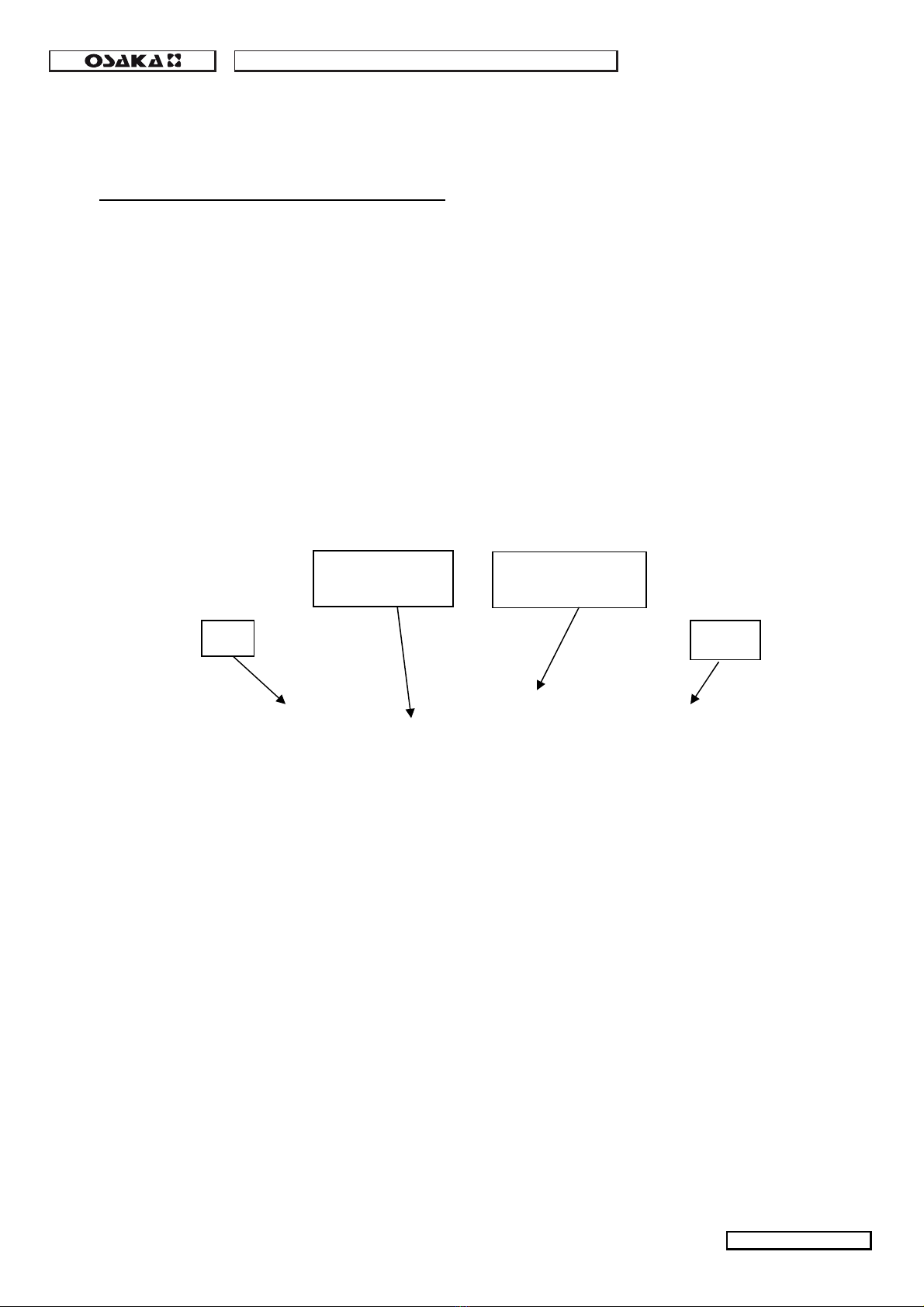
3.1 USB Connection - Ethernet 10/100
With this connection is possible:
• To connect the PRO 08D with a personal comp uter; through PRO-GRAPH
workbench it is possible to download and debug the application.
• To visit your own website; it is possibl e to download your website on the
PRO 08D to read/write variables.
The PC c an communicate with the PRO 08D only if the settings in the devices are
aligned; this means that the PC and the PRO 08D have to work in the same network.
It is also necessary to have a USB-ETHERNET converter.
The procedure is the following:
• Disconnect your computer from your co mpany network and connect the PC with the
PRO 08D through the Crossover cable.
• The personal computer has to be set in the same network of the PRO 08D.
o In the windows environment click with the mouse on “start” button .
o Choose “Control Panel” and select “Network and Internet connections”
o Choose “Local area connection” .
PRO
Cable
(Crossover)
PC
Converter
Usb-Ethernet
Page 8/ 13
Quick reference guide PRO 08D

o Choose “Properties” and double click on “Internet Protocol (TCP/IP)”
o In this window set the following parameters (as showed in the picture):
IP address: 192.168.0.200 (or the address relative to your network)
Subnet Mask: 255.255.255.0
o Click “OK” to confirm.
In order to verify the connection, please follow this procedure:
• From your PC go to Start Æ run
• In the box write the following string:
(With the IP address of your PRO)
• Click “OK” to confirm.
Page 9/ 13
Quick reference guide PRO 08D
If you want to change the device setting, please follow this procedure.
Launch the browser in your computer and write the following web site address:
http://192.168.0.250 (if your IP is different, write the correct one):
Insert the password of the application or the default one, and click OK.
If necessary, the configuration can be modified; click the Configuration button.
How to change parameters:
Click OK to confirm.
Turn the device OFF and then ON to display new values.
Click Restore Configuration to restore the default values.
Page 10 / 13
Quick reference guide PRO 08D
Table of contents
Other Osaka Control Unit manuals

Popular Control Unit manuals by other brands

Festo
Festo Compact Performance CP-FB6-E Brief description

Elo TouchSystems
Elo TouchSystems DMS-SA19P-EXTME Quick installation guide

JS Automation
JS Automation MPC3034A user manual

JAUDT
JAUDT SW GII 6406 Series Translation of the original operating instructions

Spektrum
Spektrum Air Module System manual

BOC Edwards
BOC Edwards Q Series instruction manual

KHADAS
KHADAS BT Magic quick start

Etherma
Etherma eNEXHO-IL Assembly and operating instructions

PMFoundations
PMFoundations Attenuverter Assembly guide

GEA
GEA VARIVENT Operating instruction

Walther Systemtechnik
Walther Systemtechnik VMS-05 Assembly instructions

Altronix
Altronix LINQ8PD Installation and programming manual


