Sony HDCU1000 User manual

HD CAMERA CONTROL UNIT
HDCU1000
HDCU1080
HDCU1500
SD ENCODER UNIT
HKCU1001
MULTI INTERFACE UNIT
HKCU1003
SDI OUTPUT EXPANSION UNIT
HKCU1005
INSTALLATION MANUAL
1st Edition (Revised 4)
Serial No. 10001 and Higher : HDCU1000 (UC)
Serial No. 30001 and Higher : HDCU1000 (J)
Serial No. 40001 and Higher : HDCU1000 (CE)
Serial No. 50001 and Higher : HDCU1000 (E3)
Serial No. 60001 and Higher : HDCU1000 (E2)
Serial No. 50001 and Higher : HDCU1080 (CN)
Serial No. 10001 and Higher : HDCU1500 (SY)
Serial No. 30001 and Higher : HDCU1500 (J)

.IM/HDCU1000 Series
!WARNING
This manual is intended for qualified service personnel only.
To reduce the risk of electric shock, fire or injury, do not perform any servicing other than that
contained in the operating instructions unless you are qualified to do so. Refer all servicing to
qualified service personnel.
!WARNUNG
Die Anleitung ist nur für qualifiziertes Fachpersonal bestimmt.
Alle Wartungsarbeiten dürfen nur von qualifiziertem Fachpersonal ausgeführt werden. Um die
Gefahr eines elektrischen Schlages, Feuergefahr und Verletzungen zu vermeiden, sind bei
Wartungsarbeiten strikt die Angaben in der Anleitung zu befolgen. Andere als die angegeben
Wartungsarbeiten dürfen nur von Personen ausgeführt werden, die eine spezielle Befähigung
dazu besitzen.
!AVERTISSEMENT
Ce manual est destiné uniquement aux personnes compétentes en charge de l’entretien. Afin
de réduire les risques de décharge électrique, d’incendie ou de blessure n’effectuer que les
réparations indiquées dans le mode d’emploi à moins d’être qualifié pour en effectuer d’autres.
Pour toute réparation faire appel à une personne compétente uniquement.
Attention-when the product is installed in Rack:
1. Prevention against overloading of branch circuit
When this product is installed in a rack and is
supplied power from an outlet on the rack, please
make sure that the rack does not overload the
supply circuit.
2. Providing protective earth
When this product is installed in a rack and is
supplied power from an outlet on the rack, please
confirm that the outlet is provided with a suitable
protective earth connection.
3. Internal air ambient temperature of the rack
When this product is installed in a rack, please make
sure that the internal air ambient temperature of the
rack is within the specified limit of this product.
4. Prevention against achieving hazardous
condition due to uneven mechanical loading
When this product is installed in a rack, please make
sure that the rack does not achieve hazardous
condition due to uneven mechanical loading.
5. Install the equipment while taking the operating
temperature of the equipment into consideration
For the operating temperature of the equipment,
refer to the specifications of the Operation Manual.
For safety, do not connect the connector for peripheral
device wiring that might have excessive voltage to the
following port(s).
: Ethernet connector
Follow the instructions for the above port(s).

1 (E)
.IM/HDCU1000 Series
Table of Contents
2. System Setup
2-1. System Connection .................................................. 2-1 (E)
2-1-1. HDCU1000 ..................................................... 2-2 (E)
2-1-2. HDCU1080 ..................................................... 2-7 (E)
2-1-3. HDCU1500 ................................................... 2-11 (E)
2-2. Setting the System Format ..................................... 2-16 (E)
2-2-1. Setting the Multi-Format .............................. 2-16 (E)
2-2-2. Setting the Reference Input .......................... 2-16 (E)
2-3. Audio System ......................................................... 2-17 (E)
2-3-1. Setting the Intercom System ........................ 2-17 (E)
2-3-2. Setting the Microphone ................................ 2-19 (E)
2-4. Systems .................................................................. 2-20 (E)
2-4-1. Setting the Tally System .............................. 2-20 (E)
2-4-2. Setting the Camera Number ......................... 2-20 (E)
2-4-3. Connecting the Control, Intercom,
Tally and Audio Signals ............................... 2-21 (E)
2-5. Video Signal System .............................................. 2-22 (E)
2-5-1. Selecting the Input/Output Signal ................ 2-22 (E)
2-5-2. Adjusting the Signal Phase ........................... 2-22 (E)
2-5-3. Setting Aspect Ratio Conversion during
Down-convert ............................................... 2-23 (E)
2-5-4. Adjusting the Level of the VBS Signal
(only when HKCU1001/1003 is installed) ... 2-25 (E)
2-5-5. Adjusting the Level of Signals for
Waveform Monitor ....................................... 2-25 (E)
2-5-6. Adjusting the Level of Signals for
Picture Monitor ............................................ 2-28 (E)
2-5-7. Setting the RET Input ................................... 2-29 (E)
3. Menu Settings
3-1. Menu Operation ....................................................... 3-1 (E)
3-1-1. When version of the software prior to
V1.10 .............................................................. 3-1 (E)
3-1-2. When software V1.10 or later version is
used without the system connection mode
via Ethernet set ............................................... 3-2 (E)
3-1-3. When software V1.10 or later version is
used with the system connection mode
via Ethernet set ............................................... 3-3 (E)
Manual Structure
Purpose of this manual ........................................................... 3 (E)
Related manuals ..................................................................... 3 (E)
Trademarks ............................................................................. 3 (E)
1. Installation Overview
1-1. Checking the ROM and Software Version .............. 1-1 (E)
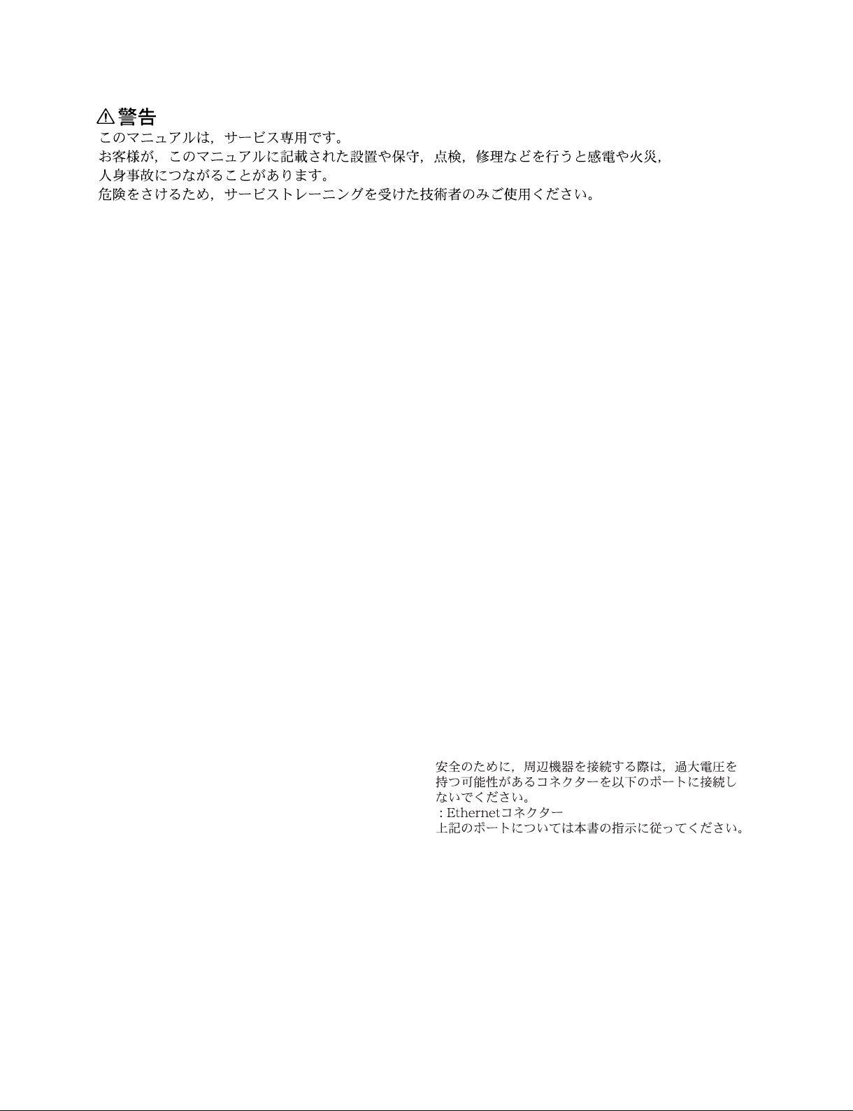
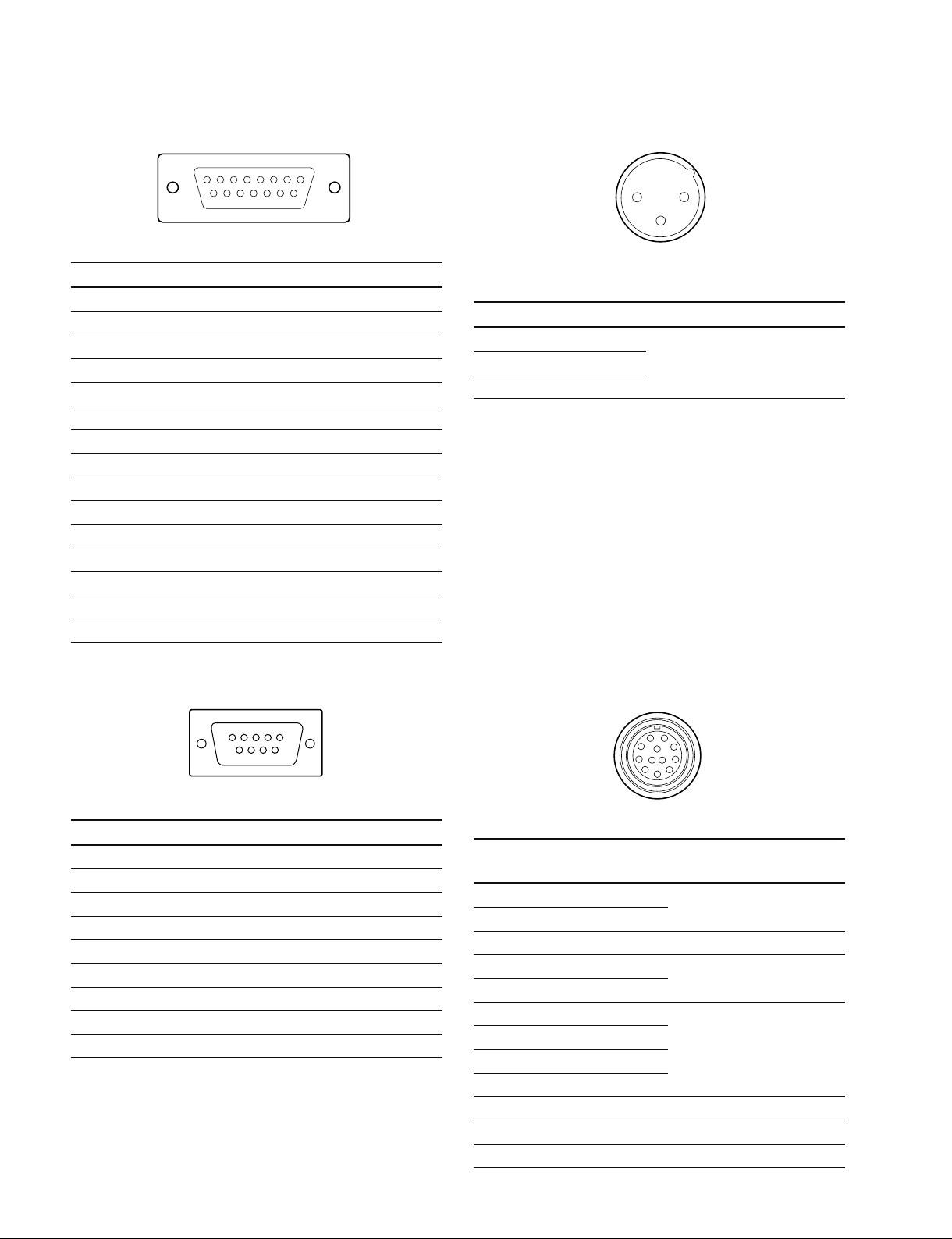
1-2. Connectors and Cables ............................................ 1-2 (E)
1-2-1. Connector Input/Output Signal ...................... 1-2 (E)
1-2-2. Cable Wiring Diagram ................................... 1-6 (E)
1-2-3. Connection Connectors .................................. 1-7 (E)
1-2-4. Note when Connecting CAMERA
Connector ....................................................... 1-7 (E)
1-3. Circuit Boards and Main Parts Layouts ................... 1-8 (E)
1-3-1. Circuit Boards and Main Parts Layouts
(HDCU1000/1080) ......................................... 1-8 (E)
1-3-2. Circuit Boards and Main Parts Layouts
(HDCU1500) .................................................. 1-9 (E)
1-4. External Dimensions .............................................. 1-10 (E)
1-4-1. HDCU1000/1080 ......................................... 1-10 (E)
1-4-2. HDCU1500 ................................................... 1-10 (E)
1-5. Removing/Installing the Front Panel ..................... 1-10 (E)
1-5-1. Removing/Installing the Front Panel
(HDCU1000/1080) ....................................... 1-10 (E)
1-5-2. Removing/Installing the Front Panel
(HDCU1500) ................................................ 1-10 (E)
1-6. Installing the RM-B750 ......................................... 1-11 (E)
1-7. On-board Indicator/Switch/Volume Functions ...... 1-13 (E)
1-8. Notes on Using the Power Supply Unit ................. 1-25 (E)
1-8-1. Setting the Power Voltage
(HDCU1000/1080) ....................................... 1-25 (E)
1-8-2. Replacing the Fuse (HDCU1000/1080) ....... 1-26 (E)
1-9. Installation Position of the Option Board .............. 1-26 (E)
1-9-1. HDCU1000/1080 ......................................... 1-27 (E)
1-9-2. HDCU1500 ................................................... 1-29 (E)
1-10. Installing the Option Boards .................................. 1-30 (E)
1-10-1. HDCU1000 ................................................... 1-30 (E)
1-10-2. HDCU1080 ................................................... 1-31 (E)
1-10-3. HDCU1500 ................................................... 1-32 (E)
1-11. Installing in 19-inch Rack (HDCU1000/1080) ...... 1-33 (E)
1-12. Cleaning of Connector/Cable ................................ 1-36 (E)

2 (E) .IM/HDCU1000 Series
3-2. Status Display .......................................................... 3-4 (E)
3-2-1. When software prior to V1.10 or V1.10
and later version is used without the system
connection mode via Ethernet set ................... 3-4 (E)
3-2-2. When software V1.10 or later version is
used with the system connection mode
via Ethernet set ............................................... 3-8 (E)
3-3. System Menu ......................................................... 3-12 (E)
3-4. Configuration Menu ............................................... 3-16 (E)
3-4-1. When version of the software prior to
V1.10 ............................................................ 3-16 (E)
3-4-2. When V1.10 or a later version of
the software .................................................. 3-20 (E)
3-5. Network Setting Menu ........................................... 3-26 (E)

3 (E)
.IM/HDCU1000 Series
Purpose of this manual
This manual is the installation manual of the following models :
HD Camera Control Unit HDCU1000/HDCU1080/HDCU1500
SD Encoder Unit HKCU1001
Multi Interface Unit HKCU1003
SDI Output Expansion Unit HKCU1005
This manual is intended for use by trained system and service engineers, and
describes the information regarding the installation of the unit and the information
that premises the service based on components replacement.
Related manuals
Beside this Installation Manual, the following manuals are available for the unit.
.Operation Manual (Supplied with HDCU1000/1500)
This manual describes how to operate the HDCU1000/1500.
.Operation Manual (Supplied with HDCU1080)
This manual describes how to operate the HDCU1080.
.Maintenance Manual (Available on request)
This manual intended for use by trained system and service engineers describes
(service overview and the circuit overview, the main part replacements, electrical
alignment, parts list, semiconductor pin assignments, block diagrams, schematic
diagrams, board layouts.) required for parts-level service.
For obtaining, contact your local Sony Sales Office/Service Center.
Part number : 9-968-208-0X
.“Semiconductor Pin Assignments” CD-ROM (Available on request)
This “Semiconductor Pin Assignments” CD-ROM allows you to search for
semiconductors used in Broadcast and Professional equipment.
This manual contains a complete list of semiconductors and their ID Nos., and
thus should be used together with the CD-ROM.
Part number: 9-968-546-06
Trademarks
Trademarks and registered trademarks used in this manual are follows.
.Clear-Com is a registered trademark of Clear-Com Intercom Systems.
.Accuride is a registered trademark of Accuride International Corporation.
Manual Structure


.IM/HDCU1000 Series 1-1 (E)
Section 1
Installation Overview
1-1. Checking the ROM and Software Version
When connecting the following peripheral equipment to the unit, confirm the versions of the ROMs and
software which are installed in each model. If the version is lower than the following one, the ROM
needs to be replaced and the software needs to be upgraded.
In this case, contact your local Sony Sales Office/Service Center.
ROM
Peripheral equipment Board Ref. No. ROM version
MSU-700A/750 CPU-293/CPU-286 IC5, IC6/IC5, IC6 Ver.1.30 or higher
MSU-900 CPU-396 IC18, IC31 Ver.1.02 or higher
CNU-700 AT-89 or AT-89A IC4, IC5 Ver.3.20 or higher
CNU-500 AT-100 IC4, IC5 Ver.2.80 or higher
RCP-720/721 MPU-79 IC10 Ver.2.90 or higher
RCP-730/731 MPU-79 IC10 Ver.2.90 or higher
RCP-740/741 MPU-79 IC10 Ver.2.90 or higher
RCP-700/701 MPU-92 IC6 Ver.2.90 or higher
Software
Peripheral equipment Board Software version
RCP-750/751 MPU-123 Ver.1.21 or higher
RM-B750 MPU-124 Ver.1.00 or higher
HDC-900/950 AT-130 Ver.1.20 or higher

1-2 (E) .IM/HDCU1000 Series
1-2. Connectors and Cables
1-2-1. Connector Input/Output Signal
BNC connector
HDCU1000/1080
SDI OUTPUT (1-4) : BNC
Conforms to BTA-S004B, 0.8 V p-p, 75 Z, 1.485 Gbps/
1.4835 Gbps
SMPTE 292M
or
Component serial signal : 0.8 V p-p, 75 Z, 270 Mbps
SMPTE 259M
RETURN INPUT
..
..
.HD SDI (1-4) : BNC
Conforms to BTA-S004B, 1.485 Gbps/1.4835 Gbps
SMPTE 292M
..
..
.SD SDI (1-4) : BNC
Component serial signal : 270 Mbps
SMPTE 259M
..
..
.VBS (1-4) : BNC
Analog composite signal : 1.0 V p-p, 75 Z
INPUT
..
..
.REFERENCE : BNC
±0.3 V, ternary SYNC, 75 Z
or 0.286 V p-p, black burst signal, 75 Z
..
..
.PROMPTER (1-2) : BNC
1.0 V p-p, 75 Z
OUTPUT
..
..
.SYNC : BNC
±0.3 V, ternary SYNC, 75 Z
0.3 V p-p, SD SYNC, 75 Zselectable
..
..
.CHARACTER : BNC
1.0 V p-p, 75 Z
..
..
.AES/EBU : BNC
AES/EBU format
HDCU1500
SDI OUT (1-3) : BNC
Conforms to BTA-S004B, 0.8 V p-p, 75 Z, 1.485 Gbps/
1.4835 Gbps
SMPTE 292M
or
Component serial signal : 0.8 V p-p, 75 Z, 270 Mbps
SMPTE 259M
RET (1-3) IN : BNC
Conforms to BTA-S004B, 1.485 Gbps/1.4835 Gbps
SMPTE 292M
or
Component serial signal : 270 Mbps
SMPTE 259M
or
Analog composite signal : 1.0 V p-p, 75 Zselectable
REFERENCE IN : BNC
±0.3 V, ternary SYNC, 75 Z
or 0.286 V p-p, black burst signal, 75 Z
PROMPTER IN : BNC
1.0 V p-p, 75 Z
CHARACTER/SYNC OUT : BNC
1.0 V p-p, 75 Z
or
±0.3 V, ternary SYNC, 75 Z
0.3 V p-p, SD SYNC, 75 Zselectable

.IM/HDCU1000 Series 1-3 (E)
HKCU1001/1003
VBS (1-2) OUT : BNC
1.0 V p-p, 75 Z
PIX OUT : BNC
1.0 V p-p, 75 Z
WF OUT : BNC
0.714 V p-p, 75 Z
ENC : 1.0 V p-p
HKCU1003
FRAME REF IN : BNC
0.3 V p-p FRAME SYNC pulse, 75 Z
or
±0.3 V, ternary SYNC, 75 Z
or 0.286 V p-p, black burst signal, 75 Z
FRAME REF OUT : BNC
THROUGH OUT/0.3 V p-p FRAME SYNC pulse, 75 Z
PIX OUT : BNC
1.0 V p-p, 75 Z
WF OUT : BNC
0.714 V p-p, 75 Z(NTSC)
0.7 V p-p, 75 Z(PAL)
ENC : 1.0 V p-p
VBS OUT : BNC
1.0V p-p, 75 Z
R-Y/R OUT : BNC
R-Y : 0.7 V p-p, 75 Z(NTSC, SETUP : ON, when
outputting 75% color bar)
0.525 V p-p, 75 Z(PAL, when outputting 75% color bar)
R : 0.7 V p-p, 75 Z
Y/G OUT : BNC
Y : 1.0 V p-p (Video : 0.714 V, synchronous 0.286 V,
NTSC), 75 Z
1.0 V p-p (Video : 0.7 V, synchronous 0.3 V, PAL), 75 Z
G : 0.7 V p-p, 75 Z
B-Y/B OUT : BNC
B-Y : 0.7 V p-p, 75 Z(NTSC, SETUP : ON, when
outputting 75% color bar)
0.525 V p-p, 75 Z(PAL, when outputting 75% color bar)
B : 0.7 V p-p, 75 Z
WF REMOTE (D-sub 15P, Female) (HDCU1000/1080)
__
__
_EXT VIEW __
__
_
No. Signal Specifications
1 NC No connection
2 NC No connection
3 NC No connection
4 NC No connection
5 RECALL2 (G) LOW ACTIVE
6 RECALL3 (B)
7 RECALL1 (R)
8 RECALL4 (SEQ)
9 GND
10 NC No connection
11 NC No connection
12 RECALL5 (ENC) LOW ACTIVE
13 RECALL6 (R+B)
14 RECALL7 (R+G)
15 RECALL8 (G+B)
15 9
18
HKCU1005
SDI OUT (1-4) : BNC
Conforms to BTA-S004B, 0.8 V p-p, 75 Z, 1.485 Gbps/
1.4835 Gbps
SMPTE 292M
or
Component serial signal : 0.8 V p-p, 75 Z, 270 Mbps
SMPTE 259M
CAMERA connector
(optical/electrical composite connector)
VIDEO Y/PB/PR
Conforms to BTA-S004B, 1.485 Gbps/
1.4835 Gbps serial
SMPTE 297M
RET VIDEO Y/PB/PR
Conforms to BTA-S004B, 1.485 Gbps/
1.4835 Gbps serial
SMPTE 297M
INCOM 2ch
MIC 2ch
DIGITAL AUDIO (AES/EBU)
CAMERA COMMAND
PROMPTER

1-4 (E) .IM/HDCU1000 Series
5
96
1
TRUNK LINE (D-sub 9P, Female) (HDCU1000/1080)
__
__
_EXT VIEW __
__
_
No. Signal Specifications
1 NC No connection
2 EXT-CMD0-IN (RXD IN)
3 EXT-CHD0-OUT (TXD OUT)
4 NC No connection
5 GND
6 NC No connection
7 NC No connection
8 NC No connection
9 NC No connection
I/O PORT (D-sub 15P, Female) (HDCU1000/1080)
__
__
_EXT VIEW __
__
_
No. Signal Specifications
1 IN1 GND/+5 V, OPEN (47 kZ+5 V PULL UP)
2 IN2 GND/+5 V, OPEN (47 kZ+5 V PULL UP)
3 IN3 GND/+5 V, OPEN (47 kZ+5 V PULL UP)
4 IN4 GND/+5 V, OPEN (47 kZ+5 V PULL UP)
5 IN5 GND/+5 V, OPEN (47 kZ+5 V PULL UP)
6 IN6 GND/+5 V, OPEN (47 kZ+5 V PULL UP)
7 IN7 GND/+5 V, OPEN (47 kZ+5 V PULL UP)
8 IN8 GND/+5 V, OPEN (47 kZ+5 V PULL UP)
9 GND
10 OUT1 0/+5 V (1 kZ)
11 OUT2 0/+5 V (1 kZ)
12 OUT3 0/+5 V (1 kZ)
13 OUT4 0/+5 V (1 kZ)
14 OUT5 0/+5 V (1 kZ)
15 OUT6 0/+5 V (1 kZ)
15 9
18
12
3
MIC1/MIC2 (XLR 3P, Male)
__
__
_EXT VIEW __
__
_
(0 dBu = 0.775 Vrms)
No. Signal Specifications
1 MIC OUT (G) 0 dBu/_20 dBu
2 MIC OUT (X) (Selectable with S500,
3 MIC OUT (Y) S501/AVP-6 board)
TRUNK A (12P, Female)
__
__
_EXT VIEW __
__
_
No. Signal Specifications
RS422A RS232C
A TX1 (_)_TRUNK Data out
B TX1 (+)_
C NC NC No connection
D TX0 (+) TX1 TRUNK Data out
E TX0 (_) TX0
F RX0 (_) RX0 TRUNK Data in
G RX0 (+) RX1
H RX1 (+)_
J RX1 (_)_
K GND GND GND for command
L NC NC No connection
M NC NC No connection
A
B
D
H
L M
F
K
J
C
E
G

.IM/HDCU1000 Series 1-5 (E)
RCP/CNU (8P, Female)
__
__
_EXT VIEW __
__
_
No. Signal Specifications
1 TX (+) SERIAL DATA OUT
2 TX (_)
3 RX (+) SERIAL DATA IN
4 RX (_)
5 TX GND GND for TX
6 POWER (+) OUT RCP POWER, +30 V
7 POWER (_) OUT GND for POWER
8 VIDEO (X) 75Z, 1.0 V p-p
CHASSIS GND CHASSIS GND
41
32
12 V
+1
_6
RG B DC 0 ±2 V
1
2
3
45
6
7
8
MIC REMOTE (D-sub 15P, Female)
__
__
_EXT VIEW __
__
_
No. Signal Specifications
1+5.5 V OUT Max. 250 mA
2 TALLY GND GND for TALLY
3 G TALLY OUT ON (GND) : Max. 30 mA IN
4 R TALLY OUT ON (GND) : Max. 30 mA IN
5 CHU MIC CONT2 *1 Refer to the right column.
6 AMP CONT1
7 GAIN IN CONT0
8 MIC1 GAIN CONT *2 Refer to the right column.
ON/OFF IN
9 GND GND for +5.5 V
10 TALLY OUT R/G TALLY OUT
ON (GND) : Max. 30 mA IN
11 PREVIEW OUT ON (GND) : 47 kZ+5 V PULL UP
12 ASPECT REMOTE L : REMOTE
ON/OFF
13 ASPECT CONT1 *3 Refer to the right column.
14 CTL CONT2
15 MIC2 GAIN CONT *2 Refer to the right column.
ON/OFF IN
15 9
18
*1 : CHU MIC 1/2 AMP GAIN
CONT0 CONT1 CONT2 CHU MIC AMP GAIN
H H H 60 dB
L H H 50 dB
H L H 40 dB
L L H 30 dB
H H L 20 dB
*2 :
8pin 15pin MIC GAIN CONT
L L MIC 1 and 2 ON
L H MIC 1 ON
H L MIC 2 ON
H H INTERNAL set
*3 :
CONT1 CONT2 ASPECT
L H SQ (16 : 9)
H H EC (4 : 3)
L L INTERNAL set
H L LB (4 : 3)
WF MODE (4P, Female)
__
__
_EXT VIEW __
__
_
No. Signal Specifications
1 SEQ CONT OUT (G) OPEN COLLECTOR
+(PNP)/_(NPN)
2 SEQ CONT OUT (X)
(Selectable with S411/AT board)
3 STAIR CASE OUT (X) *6
4 STAIR CASE OUT (G) GND for STAIR CASE
*6 : Stair Case signal

1-6 (E) .IM/HDCU1000 Series
INTERCOM/TALLY/PGM (D-sub 25P, Female)
__
__
_EXT VIEW __
__
_
(0 dBu = 0.775 Vrms)
No. Signal Specifications
1 ENG (R) (X) OUT ENG SYSTEM RECEIVE
2 ENG (R) (Y) OUT 0 dBu BALANCED
3 ENG (G) GND for ENG
4 ENG (T) (X) IN ENG SYSTEM TALK
5 ENG (T) (Y) IN 0 dBu BALANCED
6 PGM1 (X) IN _20 dBu/0 dBu
7 PGM1 (Y) IN (Selectable with
8 PGM1 (G) IN S502/AVP board)
9 GND GND for AUX
10 AUX3
11 R TALLY (X) IN ON : 24 Vdc, TTL (H), SHORT
12 R TALLY (Y) IN OFF : 0 Vdc, TTL (L), OPEN
13 GND CHASSIS GND
14 PROD (R) (X) OUT PROD SYSTEM
15 PROD (R) (Y) OUT RECEIVE 0 dBu BALANCED
16 PROD (G) GND for PROD
17 PROD (T) (X) IN PROD SYSTEM TALK
18 PROD (T) (Y) IN 0 dBu BALANCED
19 PGM2 (X) IN _20 dBu/0 dBu
20 PGM2 (Y) IN (Selectable with
21 PGM2 (G) IN S503/AVP board)
22 AUX4
23 AUX5
24 G TALLY (X) IN ON : 24 Vdc, TTL (H), SHORT
25 G TALLY (Y) IN OFF : 0 Vdc, TTL (L), OPEN
25 14
113
INTERCOM (5P, Female)
__
__
_EXT VIEW __
__
_
(0 dBu = 0.775 Vrms)
No. Signal Specifications
1 INCOM (T) IN (Y) _20 dBu
(CARBON MIC)
2 INCOM (T) IN (X) _60 dBu
(DYNAMIC MIC)
3 INCOM (T) IN (G) GND for INCOM
4 INCOM (R) OUT (X) Max. 12 dBu
5 NC No connection
1
2
3
4
5
1-2-2. Cable Wiring Diagram
CCA-5 cable (RCP/CNU connector)
Black
White
White
Brown
White
Red
Red
Brown Brown
Orange
1
2
3
4
8
5
6
7
1
2
3
4
8
5
6
7
_8P CONNECTOR (MALE) _
(WIRING SIDE)

.IM/HDCU1000 Series 1-7 (E)
Connector Connector/cable
HDCU1080 1-569-370-12 PLUG, BNC or
SLOT1 (1-4) BELDEN8281 Cable or
HD SDI (1-4) equivalent
SD SDI (1-4)
HDCU1500
SDI (1-3)
RET (1-3)
HKCU1005
SDI OUT (1-4)
(BNC)
MIC 1/2 1-508-083-00 XLR 3P Female
(3P, Male) or CANNON XLR-3-11C
equivalent
WF REMOTE/MIC REMOTE 1-506-582-11 D-sub 15P, Male
I/O PORT or JAE DA-CI-J10 equivalent
(D-sub 15P, Female)
INTERCOM/TALLY/PGM D-sub 25P, Male
(D-sub 25P, Female) JAE DA-25PF-N equivalent
WF MODE 1-560-155-00 PLUG, 4P Male
(4P, Female) (supplied)
RCP/CNU 1-766-848-11 PLUG, 8P Male
(8P, Female)
or CCA cable assembly (optional)
CCA-5-10 (10 m), CCA-5-3 (3 m)
INCOM 1-508-370-11 XLR 5P, Male
(5P, Female) or CANNON XLR-5-12C
equivalent
TRUNK LINE 1-560-651-00 D-sub 9P, Male
(D-sub 9P, Female) or JAE DE-9PF-N equivalent
1-561-749-00 JUNCTION SHELL
TRUNK A 1-819-261-11 12P, Male
(12P, Female) TAJIMI ELECTRONICS CO., LTD.
PRC07-P12M
*1 : Caution in making the optical/electric signal composite cable:
When making the optical/electric signal composite cable used for this
camera system, the connection connectors specified in this manual
must be used in order to comply with the limits for EMC regulations.
1-2-4. Note when Connecting CAMERA
Connector
Before connecting the unit to the camera adaptor, clean the
following optical contact blocks.
For the cleaning procedure, refer to Section 1-12, “Clean-
ing of Connector/Cable”.
.CAMERA connector of the unit
.CCU connector of the camera side
.Optical/electric signal composite cable
1-2-3. Connection Connectors
When connecting cables to each connector of the connec-
tor panel during installation or service, connect the follow-
ing connectors or equivalent to the tip.
Connector Connector/cable
HDCU1000/1080/1500
CAMERA .LEMO®
PUW. 3K. 93C. TLCC96 *1
(HDC1000/1100/1400/1500/1580/1600 side)
CCU .LEMO®
FUW. 3K. 93C. TLMC96 *1
HDCU1000/1080 1-564-742-11 PLUG, BNC
VBS (1-4) or B-B Cable assembly
PROMPTER (1-2) (1.5 m, optional)
REFERENCE
SYNC
CHARACTER
AES/EBU
HDCU1500
REFERENCE
PROMPTER
CHARACTER/SYNC
HKCU1001/1003
VBS (1-2)
PIX OUT
WF OUT
HKCU1003
FRAME REF IN
FRAME REF OUT
PIX OUT
WF OUT
VBS
R-Y/R
Y/G
B-Y/B
(BNC)
HDCU1000 1-569-370-12 PLUG, BNC or
SLOT1 (1-4) BELDEN8281 Cable or
SLOT2 (1-4) equivalent
HD SDI (1-4)
SD SDI (1-4)
(BNC)

1-8 (E) .IM/HDCU1000 Series
1-3. Circuit Boards and Main Parts Layouts
1-3-1. Circuit Boards and Main Parts Layouts (HDCU1000/1080)
1VIF-34/34G board
2ADO-10/10G
board
3SDI-86/86G board
4SDI-85 board
5HIF-25 board
6MB-1071/1071A
board
7AU-302 board
8AT-167 board
9AVP-6 board
!/ DTX-5 board
!- CN-2718 board
!= CN-2673 board
![ CN-2672/2672G
board
!] CN-2805/2805G
board
!\ SDP-12 board
!; CNB-21/21G board
!' CN-2674/2674G
board
!, DRX-5 board
!. CN-2700 board
@[ HIF-25 board
10001_13999 (HDCU1000: UC)
40001_40999 (HDCU1000: CE)
50001_51999 (HDCU1080: CN)
HIF-26 board
14001 and Higher (HDCU1000: UC)
41001 and Higher (HDCU1000: CE)
52001 and Higher (HDCU1080: CN)
50001 and Higher (HDCU1000: E3)
60001 and Higher (HDCU1000: E2)
@/ EN-159A board (HKCU1001)
EN-159B board (HKCU1003)*
DRX-5 board (HKCU1005)
@- VDA-64A board (HKCU1001)
VDA-64A board (HKCU1003)*
VDA-64B board (HKCU1003)*
VDA-64C board (HKCU1003)*
HIF-26 board (HKCU1005)
@= DU-390 board (HDCU1080 only)
*: HKCU1003 is the option board for HDCU1000. It is not used for HDCU1080.
8
7
!.
!- != ![
!]
!\
!;
@/
90
!'
!,
!,
@= Option
Option
12
6
345
@-
Switching Regulator
@[
(HDCU1000 only)
(HDCU1000/1080)
(HDCU1000/1080)
(HDCU1000)
(HDCU1080)
@[ The installed board is different according to
the serial number of the unit.
(Refer to the serial number as shown below)

.IM/HDCU1000 Series 1-9 (E)
1-3-2. Circuit Boards and Main Parts Layouts (HDCU1500)
2
1
3
4
5
60
!,
789
!'
Option
Option
!-
!= ![
!]
!\
!;
Switching Regulator
!' EN-159A board (HKCU1001)
EN-159B board (HKCU1003)
DRX-5 board (HKCU1005)
!, VDA-64A board (HKCU1001)
VDA-64A board (HKCU1003)
VDA-64B board (HKCU1003)
VDA-64C board (HKCU1003)
HIF-26 board (HKCU1005)
1CN-2678 board
2AU-303/303G board
3AT-167 board
4AVP-6 board
5DTX-5 board
6DRX-5 board
7VIF-34B/34BG board
8ADO-10/10G board
9SDI-87/87G board
!/ HIF-27 board
!- MB-1072/1072G board
!= CN-2677/2677G board
![ CN-2676 board
!] CN-2675/2675G board
!\ SDP-12 board
!; CNB-22/22G board

1-10 (E) .IM/HDCU1000 Series
1-5. Removing/Installing the Front Panel
1-5-1. Removing/Installing the Front Panel
(HDCU1000/1080)
1. Fully loosen the two screws with stopper and remove
the front panel in the direction of the arrow.
2. Reattach the front panel in reverse order of step 1.
Front panel
Screws with stopper
1-5-2. Removing/Installing the Front Panel
(HDCU1500)
1. Loosen the two screws with stopper and open the front
panel in the direction of the arrow.
2. Reattach the front panel in reverse order of step 1.
Screw with
stopper
Screw with stopper
Front panel
1-4. External Dimensions
1-4-1. HDCU1000/1080
1-4-2. HDCU1500
424
410
465
482
132
57
20067
1243 410 32

.IM/HDCU1000 Series 1-11 (E)
1-6. Installing the RM-B750
This section describes the installation procedure when the
front panel of the remote control unit RM-B750 is used by
being installed to HDCU1500.
Removing the Front Panel from the RM-B750
1. Loosen the screw with stopper of the RM-B750 and
open the cover in the direction of the arrow.
2. Loosen the four screws with stopper and open the front
panel and the rear panel in the direction of the respec-
tive arrows.
3. Disconnect the flexible card wires from the connectors
CN2, CN14 on the VA-211 board.
n
Be careful not to bend the flexible card wires. This
shortens the wire life.
4. Remove the screw and remove the front panel in the
direction of the arrow.
Cover
Screw with stopper
Front panel
Rear panel
Screws with
stopper
Screws with stopper
Front panel
VA-211 board
MPU-124 board
(CN104)
CN2
CN14
Flexible card wire
Flexible card wire
B3 x5

1-12 (E) .IM/HDCU1000 Series
11. Connect the flexible card wires to the connectors CN3,
CN4 on the AU-303 board.
m
.Do not insert the flexible card wire sideways. Insert
it securely to the deep end as shown in the Fig 1. If
the connection is not performed correctly, it may
cause an failure.
.Be careful not to bend the flexible card wires. This
shortens the wire life.
12. Close the front panel of the RM-B750 in the direction
of the arrow and secure it with the two screws with
stopper.
n
When closing the front panel, be careful not to give
excessive force on the flexible card wires or the
connectors.
13. Upon completion of front panel installation, check that
the switch S206 (CCU-PW) on the MPU-124 board of
the RM-B750 is ON.
Installing the Front Panel to the Unit
5. Turn off the power and disconnect the plug from the
outlet.
6. Open the front panel of the unit. (Refer to Section 1-5-
2.)
7. Remove the screw.
8. Slide the front panel in the direction of the arrow to
extract the pin from the potbellied hole and remove the
front panel.
9. Insert the pin into the potbellied hole of the front panel
of the RM-B750 removed in step 4 and slide the pin in
the direction of the arrow.
n
Confirm that the pin is hooked to the potbellied hole so
that front panel does not drop.
10. Secure the front panel of the RM-B750 with the screw
removed in step 7.
Front panel
Potbellied hole
Pin
Screw with
stopper
Screw with stopper
B3 x6
Potbellied hole
Pin
B3 x6
Front panel of
the RM-B750 AU-303 board
Flexible card wires
Screw with stopper
Screw with stopper
S206
CN4
CN3
Insulated surface
(Blue)
Insulated surface
(Blue)
7.5 mm or less 7.5 mm or more Fig. 1
OK NG

.IM/HDCU1000 Series 1-13 (E)
AB C D E F G HJ
1
2
3
4
5
D4
D411
S403 S404 S405
D412
S410
S409
S408
S407
S406
S419 S418
S402
S401
S420
S416
D409
D410
S411
RV702
RV701
S103
S104
S101
S102
S413
S412
AT-167 (Side A)
AT
REF IN
UN
LOCK
H PHASE
REFERENCE
HD
RMT
SD
ADV
DELAY
1-7. On-board Indicator/Switch/Volume Functions
AT-167 board
Ref.No. Name Function
Factory default setting
D4 POWER (Green) Illuminates when the power inside the AT board starts up correctly. _
D409 REF IN (Green) Illuminates when the reference signal is input and the external _
synchronous mode is established.
D410 UNLOCK (Red) Illuminates when CCU cannot lock the external reference signal in the _
external synchronous mode.
D411 MS-LED (Red/green) Displays the access status to the Memory Stick. _
Red light: Accessing the Memory Stick. Do not remove the Memory Stick.
Green light: The inserted Memory Stick can be removed.
D412 LAN-LED*(green) Illuminates when communication is in progress via the Ethernet connector. _
S101 PRTCT Factory use ON
S102 DEBUG Factory use OFF
S103 URA Factory use OFF
S104 DEBUG Factory use OFF
S401 REFERENCE Select the type of the synchronous signal to be connected to the REFERENCE REMOTE
terminal of this unit with this switch.
HD : Synchronizes (SYNC) with the HD reference signal.
(Input frame frequency is automatically adjusted.)
REMOTE : Controls from the remote panel such as that on MSU.
SD : Synchronizes (SYNC) with the SD reference signal (BB).
The VBS OUT signal synchronizes (SC) when HKCU1001/1003 is installed.
When the setting of the switch and the type of the input synchronous signal does
not match, the LED of D410 (UNLOCK) illuminates.
S402 H-PHASE Adjusts the H-phase.
S403 H-Phase (STEP) Adjusts the level phase for the reference signal in steps. 8
S404 V-Phase Adjusts the vertical phase for the reference signal in line steps. 8
*: This function has been added to software V1.10 and the later versions.

1-14 (E) .IM/HDCU1000 Series
Ref.No. Name Function
Factory default setting
S405 V-DLY Video phase setting between HD and SD 0
Sets the phase difference (delay time) between the HD signal and the SD
signal output from CCU.
The phase can be advanced as follows based on the delay time set with S410.
HD standard: 128ck (27 MHz) increment
SD standard: 256ck (74 MHz) increment
S406 MODE1
1 MIC-GT 1&2/1,2
Sets whether or not to control MIC1 and MIC2 of the MIC GAIN CONTROL pin of the
OFF
MIC REMOTE connector independently or by interlocking the MIC1 and MIC2 controls.
ON: MIC1, MIC2 independent control MIC1 : 5 pin to 7 pin MIC2 : 12 pin to 14 pin
OFF: MIC1, MIC2 interlocked control MIC1, MIC2 : 5 pin to 7 pin
2 MIC-G7 STD/700 For switching the interface specification of MIC-Remote (D-SUB-15P) OFF
ON: Old interface (700 mode)
OFF: Standard-I/F
3 D-SUB MIC/WFM For switching the D-SUB-15P function on HDCU1500 OFF
ON: WFM-Remote
OFF: MIC-Remote
4
ASPECT RMT/PNL
ON: Accepts the switching command last input from MSU when the ASPECT OFF
switching from outside (D-Sub) is valid.
OFF: Does not accept the command input from MSU when the ASPECT
switching from outside (D-Sub) is valid.
5 Not used
6 CNU/RM For setting the priority of remote device on HDCU1500 hen the OFF
Front-PNL-RM (RM-B750) is installed
ON: Front-PNL-RM has priority.
OFF: Device connected to the Rear-RM-CMD connector has priority.
7 RCP-PX ENB/DIS Sets the monitor selection control method for PIX OUT by RCP. OFF
ON : Only WF can be controlled from RCP.
OFF : Both PIX and WF can be controlled from RCP.
8
MONI-S M&R/RCP
Sets the monitor selection control method for PIX/WF OUT. OFF
ON : Can only be controlled from RCP (PIX/WF 1 system). When there is
PIX/WF 2 system, it can be controlled from MSU.
OFF : Can be controlled from either MSU or RCP. (Latest priority)
S407 REFERENCE HD REFERENCE SD
Reference (advance amount Reference (advance amount
of SD) of HD)
00 0
1_4.74 usec _3.45 usec
2_9.48 usec _6.70 usec
3_14.2 usec _10.3 usec
4_19.0 usec _13.8 usec
5_23.7 usec _17.2 usec
6_28.4 usec _20.7 usec
7_33.2 usec _24.1 usec
8_37.9 usec _27.6 usec
9_42.7 usec _31.0 usec
A_47.7 usec _34.5 usec
B_52.1 usec _37.9 usec
C_56.9 usec _41.4 usec
D_61.6 usec _44.8 usec
E_66.3 usec _48.3 usec
F_71.1 usec _51.7 usec
1H 525 : 63.5 usec 1125-60i : 29.6 usec 750-60P : 22.2 usec
625 : 64.0 usec 1125-50i : 35.6 usec 750-50P : 26.7 usec
1125-24 PsF : 37.0 usec
Other manuals for HDCU1000
2
This manual suits for next models
5
Table of contents
Other Sony Control Unit manuals
Popular Control Unit manuals by other brands

Lutron Electronics
Lutron Electronics PowPak FC-SENSOR manual

Bentel
Bentel KYO 32 M user manual

Dataq Instruments
Dataq Instruments DI-188 user manual

Spirax Sarco
Spirax Sarco RSW Installation, operation and maintenance manual

YOKOGAWA
YOKOGAWA AQ2200-111 user manual

MicroElektronika
MicroElektronika GSM click manual