OSKA Series5 User manual
User Guide
Series5 Mattress
Version 5: 30.09.2022
Series5 Mattress User Guide 3
Contents
03 Know your symbols
04 About your mattress
06 Design features
08 How to set up your mattress
10 Using the pump
11 General directions
14 Evacuation base
15 Cleaning
16 General guidelines
18 Specications
19 Troubleshooting guide
21 Technical description
23 Appendix A: EMC information
27 Series5 preventive maintenance
and repair log
Know your symbols
This manual contains different
typefaces and symbols to make
the content easier to read and
understand:
Standard text - used for regular
information. Boldface text -
stresses a word or phrase.
NOTE: - sets apart special
information or important
instructionclarication.
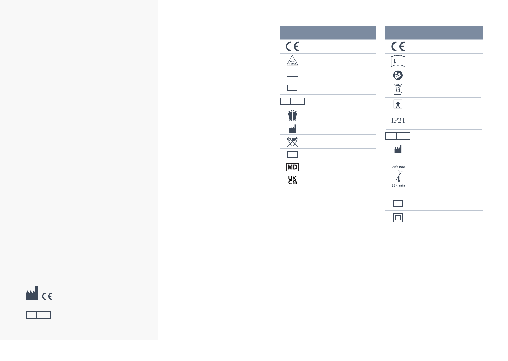
European conformity marking
See the user manual for use
instructions
See user manual for use
instructions for 230V system
WEEE
Type BF applied part
Protection against the ingress
ofngersorsimilarobjectsand
dripping water
REPEC Authorized representative in the
European Community
Manufacturer
Temperature limitation
Operation: 10°C to 40°C (50°F
to 104°F)
Storage: -15°C to 50°C (5°F to
122°F)
Shipping: -15°C to 70°C (5°F
to 158°F)
SN Serial number
Double insulation
European conformity marking
Non sterile
REF Catalogue number
SN Serial number
REPEC Authorized representative in the
European Community
Foot end
Manufacturer
Not made with natural rubber
latex
LOT Batch code
Medical Device
UKCA marked
Mattress Pump (This Pump is not an OSKA Product.)
Please read the following instructions carefully and
observe the warning instructions before using the system.
OSKA Care Ltd
Edward House, 5 Penner Road, Havant, PO9
1QZ UK
Advena Limited
Tower Business Centre, 2nd Flr.,Tower
Street, Swatar, BKR 4013 Malta
REPEC

Series5 Mattress User Guide 5
About your mattress
Description
The system consists of a foam shell with a
high-density foam topper serving as the support
surface underneath the patient.The foam shell also
includes a safety edge that bolsters at the sides of
the mattress, this provides added patient/ resident
stability and positioning.
Included in the system design is a unique Heel
Zone that is designed to further reduce pressure
for the sensitive heel area.
Within the foam body of the mattress is the
inationsystemthatconsistsofaircylinders,which
run lengthwise within the mattress.The air control
unit connects to the mattress at the patient foot-
end.
Modes of Operation
The Series5 provides options of alternating
pressure,basiclateralrotation,poweredotation
andauto-rm.
Contraindications
Not recommended for patients for whom rotation
or turning is contraindicated, such as, but not
limitedto,unstablespinalcordinjury,unstable
skeletal fractures requiring immobilisation and/
or skeletal traction, physician orders prohibiting
rotation, or severe posterior burns requiring skin
grafts.
Indications for Use
Series5mattressesarepowered,otationtherapy
mattresses providing a pressure management
surface for the prevention and treatment of
pressure ulcers.The lateral rotation mode is
indicated for use as a preventive tool against
further complications associated with critically ill
patients or immobility.
CAUTION!
The Series5 is not for use by those with
unstable spinal chords
10 ways to reduce risk of electrocution
01. Always unplug this unit immediately after
use.
02. Do not operate near water.
03. Do not place or store where it can fall
or be pulled into a bath or sink.
04. Do not place or drop into water or any
other liquid.
05. Do not reach for a product that has
fallen into water, unplug it immediately.
06. Use this unit only for its intended
purpose.
07. Never operate this product if it has a
damaged chord/plug, if it’s not working
properly, if it has been dropped or
damaged.
08. Keep the chord away from heated
surfaces.
09. Neverdroporinsertanyobjectintoany
opening.
10. Do not use outdoors.
10 Ways to reduce risk of burns,
electrocution, re or injury to persons
01. Use this unit only for its intended use as
described in the operating instructions.
02. Never operate this product if it has a
damaged cord or plug, if it is not working
properly, if it has been dropped or
damaged, or dropped into water. Return
the unit for examination and repair.
03. Keep the cord away from heated
surfaces. Discontinue use if power cord
is damaged or worn.
04. Neverdroporinsertanyobjectintoany
opening or hose. Keep away from sharp
objects.
05. Do not use outdoors.
06. Possible explosion hazard if used in the
immediateproximityofammablegases
(risk of explosion).
07. Use only original spare parts.
08. Plug this product into a correctly
grounded outlet only.
09. Before cleaning, unplug from power
source.
10. Do not use harsh cleansers, solvents, or
detergents. Do not expose the unit to
excessive moisture. Equipment damage
could occur.
CAUTION!
A notice to the user and/or patient that any
serious incident that has occurred in relation
to the device should be reported to the
manufacturer and competent authority of
the member state in which the user and/or
patient is established.
Series5 Mattress User Guide 7
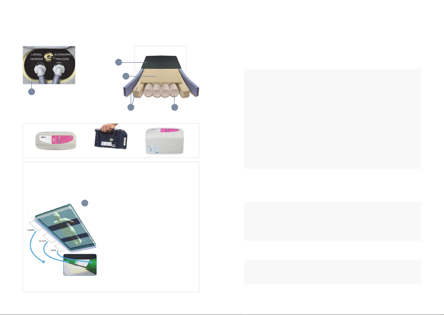
Shear zones
In addition to the modular foam top surface, the exclusive shear zones design provides an additional
measure of shearing protection in the form of the silicone-coated, shear-minimising fabric bands
located on the underside of the bi-directional stretch cover.
Standard Model Shown
Cover
Foam topper with
modular foam
design
Mattress toggle switch
Safety edge Air cylinders
The shear zone design helps:
- Prevent heels, sacrum, and scapula from “digging into”
surface.
- “Glide” user back to original position following HOB
elevation.
- Protect against damaging effects of micro shear, macro
shear, and rotational (pivot induced) shear.
- Provide patient stability by transferring shear to more
shear-tolerant anchor points.
- Polycarbonate-fortiedforunsurpassedresistance
to damaging effects of diluted bleach and other
aggressive cleaners and disinfectants.
- Engineered for ideal combination of
immersion and patient mobility.
- Environmentally friendly.
1
Cover
Design features
1
2
3 4
5
Design features
Series5 Covers
Both models include replaceable, zipped covers which are antimicrobial,
ame-resistant,uid-impervious,tear-resistant,andhave
a low moisture vapour transmission rate (MVTR). Covers easily
wipe clean with standard, hospital-grade cleaners. Cover of Series5
mattress features bi-directional stretch top fabric designed to allow
full integration of the user into the surface.Top is made from
proprietarypolycarbonate-fortiedhealthcarefabricwhichprovides
unsurpassed resistance to the damaging effects of diluted bleach and
other aggressive cleaners and disinfectants. Also includes patented
Shear Zones incorporated beneath top fabric creates shear-minimising
bands beneath heels, sacrum and scapula. Zones help prevent these
bony prominences from digging into the surface, while protecting
against the damaging effects of micro shear, macro shear, and
rotational (pivot-induced) shear. Design also helps “glide” the user
back to their original position following HOB elevation. Exclusive split
bottom design helps reduce sliding of mattress while also reducing the
“gatching noise” typical of non-slip fabrics.
See bottom of page 6 for illustration and complete description.
Foam Topper
The foam topper is a high density, medical grade foam.The unique
modular design consists of over 800 individual cells, each of which
acts individually to redistribute pressure, to reduce heat and moisture
build-up on the skin, and to reduce shear to underlying tissues.This
foam topper is 2” in height and includes the unique heel relief slope
feature, designed to further reduce pressure for the sensitive heel area.
Safety Edge Bolster
Theinationsystemconsistsoffoururethaneaircylindersinstandard
models that run head to foot underneath the body and the foam
topper.These cylinders perform the alternating pressure therapy, and
thelateralrotationtherapy.Cylindersinateanddeateinaxed
10-minutecycle.Thecyclesandinationlevelsaredesignedtoprovide
and maintain low interface pressures throughout the mattress, and to
redistribute peak interface pressure points during the alternating cycle.
Air Cylinders
Theair-cylinderinationsystemandthefoamshellworkinconcertto
maintain low interface pressures throughout the surface, making the
mattress effective for prevention and treatment of pressure ulcers.
Mattress Toggle Switch
The toggle switch changes modalities from alternating pressure to
lateral rotation.
Theswitchislocatedunderafabricaponthesideofthemattressat
the foot end.
Theair-cylinderinationsystemandthefoamshellworkinconcerttomaintainlowinterfacepressures
throughout the surface, making the mattress effective for prevention and treatment of pressure ulcers.
Shear zone
design
Series5 Mattress User Guide 9
How to set up your mattress
01. Place the Series5 mattress on the bed frame
with the airline connectors at the foot end
of the bed.The mattress has a black bottom
cover that should be placed directly on the
bed frame, the mattress cover will have airline
connectors on the bottom left corner, make
sure this matches with the airline connectors
on the mattress.The blue top cover should
face upwards, with the foot icon at the
bottom of the bed frame.
02. Check the bed frame is appropriate for use
with the mattress, i.e. the length and width of
the mattress are appropriate for the frame.
Place directly on a healthcare bedframe only,
never on top of another mattress.
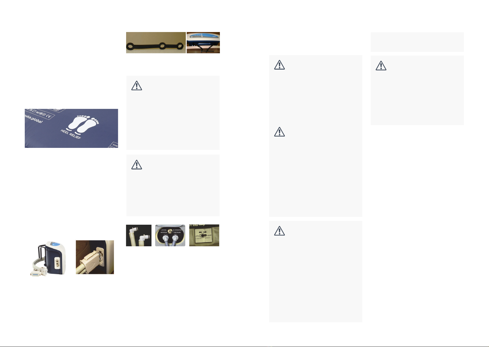
03. Hang the control unit on the foot board at
the end of the bed using fold-out hangers
(Figure A). Connect airlines to control unit by
pressing quick connector into port on the side
of unit.“Triangle” symbol should face front.
(Figure B) Audible “click” indicates secure
connection.
Pressapclosed.
NOTE: The hanger lock strip (included, item #
P10064, Fig. C) can be used to help hold control
unit more snugly in place on thin foot boards such
as those often found on home health care beds.To
use, place the strip in position around the hanger
hooks as shown in Figure D.
Figure E Figure F Figure G
Figure A Figure B
Figure C Figure D
04. Connect the ends of the air lines with two right
angle male connectors (Figure E) to the ports
on the side of the mattress. Ports (Figure F) are
locatedbeneathafabricap(FigureG)near
the left corner at the foot end of the mattress.
Ensure that the airlines are not kinked or
twisted. Press connectors into ports until you
hear an audible “click” for each.
05. Ensure that theToggle switch is in the
“Alternating Pressure” position.
WARNING!
Toavoidpotentialforinjurytopatient’sfoot,
the control unit should be positioned such
thehangersremainushtotheheadboard
and do not extend on to the sleep surface.
This may require use of the hanger lock strip.
See note above.
CAUTION!
Do not cut air lines to increase separation. If
additional separation is needed to connect
air lines to the mattress, gently pull airlines
away from one another to lengthen the split
06. Ensure that green On/Off switch at side of
control unit is “Off ”. Plug power cord into wall
outlet. Press On/ Off switch “ON”.
07. When power switch is turned to ON, the
unit will power up in “Auto Firm” mode and
beginperformingasystemcheck.Thisllsthe
airsystemcompletely,inordertoconrm
the proper connection and function of both
the mattress and the control unit prior to
a patient being placed on the surface. If the
mattress is completely empty of air, this can
take as long as 20 minutes.You must leave the
mattressforafull20minutestofullyinate
before using or trying to change the comfort
level setting.
08. System will remain in “Auto Firm” mode
until this process is complete. “Low Pressure”
indicator light and audible alarm will remain
on as well.Audible Alarm can be disengaged
during this process by pressing the Audible
Alarm On/Off button.
09. When system check is complete, the control
unit will revert to previous comfort level
setting and “Alternate” mode. Low Pressure
indicator light will turn off. System is now
ready to be set for the next user.
NOTE: If “Low Pressure” remains on after 30
minutes, call for service.
Never thread airline through mechanical parts
of the bed or bed rails where normal bed
movement may damage the airlines, power
cord or the control unit itself. Check to be
sure the motion of the bed does not interfere
with the airlines, power cord or plug.
Always plug the power cable securely into
the wall outlet. Make sure the wall-mounted
outlet will accommodate a heavy duty or
hospital-grade plug and that the outlet is in
good working order.The plug of the power
cordshouldttightlyintothewalloutlet.The
plug body, the wall outlet, and the wall plate
should not be cracked or chipped.The plug
blades should be securely retained in the plug
body.The ground pin of the plug should be
intact and secure.
Do not connect the power cord to an
extension cord or to a multiple outlet strip.
If the use of extension cords or multiple
outlet strips cannot be avoided, use only
heavy duty or hospital-grade connectors
that are approved by the facility engineering
department. Multiple outlet strips should be
mountedonaxedobjecttoreducethe
risk of liquid spills and physical damage. In
addition, if multiple-receptacle outlet boxes
are used, they also should be protected from
the risk of liquid spills and physical damage.
All extension cords and multiple outlet strips
should be tagged and inspected routinely.
Do not cover the power cord with a rug or
carpet. Rugs or carpets can prevent normal
airow,whichcanleadtogreaterheat
built-up.Placethecordinalowornotrafc
area. Check to be sure the motion of the
bed does not interfere with the bed’s power
cord or plug.
Series5 Mattress User Guide 11
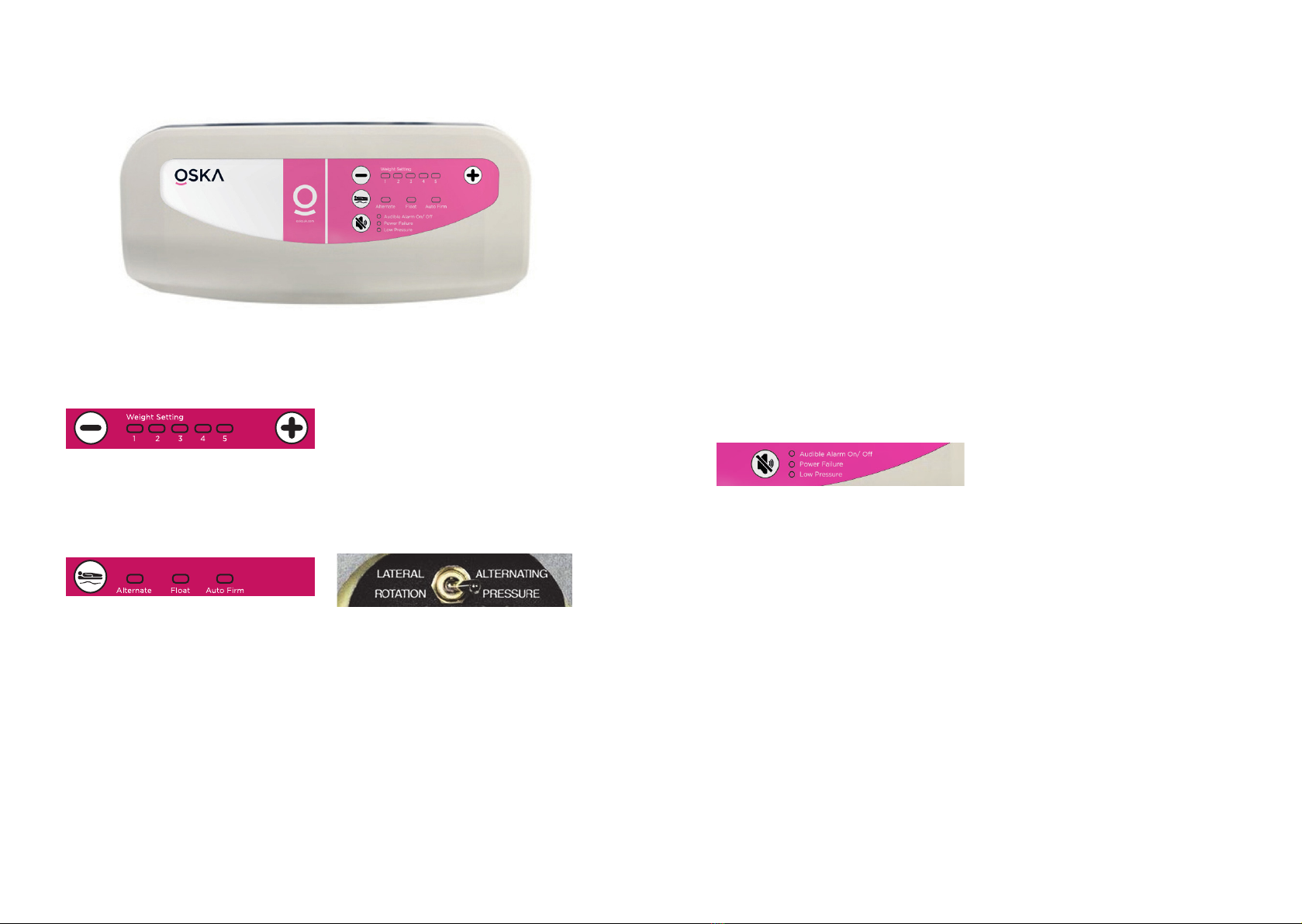
Weight level selection
Use the +/- buttons to set according to the
patient’s weight. Use the chart on the front of the
pump to select the right setting.
Mode selection
“Alternate” mode: Creates an “A-B” sequence of
inationanddeationofthemattress’sfourair
cylinders designed to change loading across the
surface in a 10-minute cycle. Use the toggle switch
on the side of the mattress to select between two
patterns of alternation:
Lateral Rotation therapy
With mattress toggle switch set to “Lateral
Rotation”,twoaircylindersononesideinate,
whilethetwoontheoppositesidedeate,gently
rotating the patient approximately 20° to one side.
Afterapproximately5minutes,theination
pattern reverses and the patient is rotated to the
opposite side.
Alternating Pressure therapy
With mattress toggle switch set to “Alternating
Pressure”,aircylinders1and3inatewhile2and
4deate.
After approximately 5 minutes, the pattern
reverses.
Using the pump “Float” (powered otation therapy) mode
Suspendscyclicalination/deationoftheair
cylindersandinsteadprovidespoweredotation
therapy.
In this mode, all four air cylinders are evenly
inated,andthesystemmaintainsidealpressure
managementbyadjustinginresponsetoany
repositioning of the user on the surface.
“Auto Firm” mode
Suspendscyclicalination/deationandsets
systemtormestinationlevelfor20minutesto
facilitate user transfer, feeding, dressing changes,
and other activities of daily living (ADLs), and CPR.
After 20 minutes, system will revert to previous
comfort setting and “Alternate” mode.
Audible Alarm On/Off
When indicator light is on, an audible alarm will
sound if either the Low Pressure or Power Failure
indicator light is on.
Press button to silence the alarm.
Alarm can also be toggled off in advance if audible
alarm is not desired for low pressure conditions
Power Failure
During power failure situation or upon power
down, the Power Failure indicator light will come
on and the audible alarm will sound. Press the
mute button to silence the alarm. (See “Power
Loss”)
Low Pressure
If “Low Pressure” indicator light comes on after
initial set-up or when moving mattress or control
unit,rstcheckthatallairlinesareproperly
connected and that they are not kinked. If light is
still on after 30 minutes, call for service.
General directions
Electromagnetic or other interference
See Appendix A p23.
This equipment generates, uses and can radiate
radio frequency energy and, if not installed and
used in accordance with the instructions, may
cause harmful interference to other devices in the
vicinity.
However, there is no guarantee that interference
will not occur in a particular installation. If this
equipment does cause harmful interference to
other devices, which can be determined by turning
the equipment off and on, the user is encouraged
to try to correct the interference by one or more
of the following measures:
- Reorient or relocate the receiving device.
- Increase the separation between the equipment.
- Connect the equipment into an outlet on a
circuit different from that to which the other
device(s) are connected.
- Consult the manufacturer for help.
Power loss / patient transport
To seal air into mattress, simply disconnect the
quick connector from the control unit, and place
“transport”
Head-of-bed elevation
All support surfaces using air as a support medium
are designed for distributing pressures over the
bodyinaat,horizontalposition.Bendingthe
support surface and the body at the midpoint
when elevating the HOB concentrates the body

Series5 Mattress User Guide 13
weight over the centre of the surface, stressing
that small area.
This extreme change in dynamics creates a
challenge for all air support surfaces. Maximum
pressuremanagementbenetsarerealised
between zero and 30° HOB elevation. Beyond
30°, the amplitude of the changes in the air
cylinders begins to decrease in proportion to the
increased elevation of the HOB. Although the
mattress will maintain its support and therapeutic
capabilities up to and including 70° HOB, for
maximumbenetwerecommendthatany
pressure management surface be used with the
head of the bed elevated as little as possible, and
for limited periods at a time.
WARNING!
DO NOT MOVE USER ON MATTRESS
ONLY.
Mattress should not be used alone for user/
patient transport.
WARNING!
Lateral rotation mode should not be
used with head of bed elevated beyond
30°. Instead, select alternating pressure or
poweredotation(oat)mode.WithHOB
elevated, the alternating pressure mode can
facilitate maximum pressure management
effectiveness while minimising the possibility
of patient falls.
Troubleshooting patient complaints
Occasionally a patient will complain of feeling as if
they are “sinking into a hole”.
01. Sometimes this happens when the head of
the bed is elevated and the mattress is in
either lateral rotation or alternating pressure.
This sensation is a combination of the
deationofthecylindersduringtheircycle
and the increased weight of the patient on
the sacrum and pelvis when the head of the
bed is elevated.This demonstrates the need
to minimise elevation of the head of the bed.
To improve this situation decrease elevation of
the head of the bed.
02. Often patients complain when they are supine
or side-lying and are not used to the changing
pressures within the air system. Reassure the
resident that this is normal functioning, as the
cylindersalternatelyinateanddeate.The
“deated”tubesarenotfullydeated.Some
air is always maintained in them to prevent
bottoming out. After reassurance, patients get
used to the changing pressures
Bed linens
Useatsheets,knittedstretch-tsheets,ordeep-
pocketttedsheets.Useasfewlayersoflinens
or underpads beneath the patient as possible to
allow best possible envelopment, immersion and
pressure management performance.
Bed rails
Due to concerns over the possibility of patient
entrapment, OSKA recognises that the use of rails
of any length is a matter currently addressed by
laws/guidelines, and by individual facility protocol.
It is the responsibility of the facility to be in
compliance with these laws, which typically require
that decisions on the use of bed rails of any type
are based on assessment of the physical and
mental status of each patient individually. If bed-rails
are needed by the patient to prevent fall-related
injury,asdeterminedbythisfacilityassessment,we
recommend that the bed-rails be locked in the up
position at all times.We do not require use of bed-
rails unless the patient is deemed to be safer with
them than without them.
CPR
TodeatethemattressforCPR,simplydetachthe
mattress from the pump by unplugging the airlines
from the pump (see Figure B).
Storage and transportation
Store the mattresses in a clean, dry place. Once
the mattress is removed from the box, store in a
atpositionifpossible.Ifmattressmustbestored
onitsside,ensurethattheinationsystemisin
correct position within the mattress prior to placing
a user on the surface. Protect from damage. Avoid
temperature extremes (below freezing or above
48°C). Allow to acclimate to room temperature
before use. Do not stack more than 10 high.
Do not stack other equipment on top of the
mattresses.
Store the control unit in a clean, dry place,
protected from accidental damage or falls.
Avoid temperature extremes (below freezing or
above 48°C). Do not stack other equipment on
top of the control unit.
Avoid storage of other equipment on top of
the mattress.When removing the mattress from
storage,alwaysensuretheinternalinationsystem
is aligned correctly prior to placing a patient on
the surface.
CAUTION!
Be careful not to puncture the mattress with
needles or sharp instruments.This may result
in loss of integrity of the cover or internal air
system. Regularly inspect the mattress cover
for cuts, rips, cracks or tears. Do not use the
mattress if the cover is damaged.
For transportation, secure to prevent damage
or falls. For shipment, use box and packaging as
provided by the manufacturer.
Environmental conditions for use of pump
• Indoor Use
• Altitude up to 2000 meters
• Operation Temperature 10°C to 40°C, Storage
Temperature: -15°C to 50°C, and Shipping
Temperature: -15°C to 70°C
• Operation humidity: 10% to 90% non-
condensing, Storage Humidity: 10% to 90%
non-condensing and Shipping humidity: 10 % to
90% non-condensing.
• Mains Supply Voltage Fluctuation up to 10 +/-%
of the nominal voltage
• Over-voltage Category II
• Pollution Degree 2
Warranty for pump
All models are unconditionally guaranteed against
failure due to manufacturing defects under normal
use for 18 months.
Use in wound care
Use of Series5 mattress is only one element of
care in the prevention and treatment of pressure
ulcers. Frequent repositioning, proper care, routine
skin assessment, wound treatment and proper
nutrition are but a few of the elements required
in the prevention and treatment of pressure
ulcers. As there are many factors that may
inuencethedevelopmentofapressureulcerfor
each individual, the ultimate responsibility in the
prevention and treatment of pressure ulcers is with
the health care professional.

Series5 Mattress User Guide 15
Evacuation base
The Series5 comes with evacuation straps within
it‘s base.
It is very important that the safety equipment, as
well as the evacuation procedures, are well planned
and known in advance.
Thesecoverscansignicantlyhelpyoubeprepared
inthecaseofareorotheremergencywhenaless
mobile patient will need to be evacuated.
Handles appear on all 4 sides of the cover and the
velcroreevacuationstrapsarehousedsecurely
in pockets on the 2 longer sides with their ends
sticking out for easy access.These straps are used in
the case of an emergency to secure the patient to
the mattress before transporting them to safe area.
Evacuation instructions
• Let the patient know what is about to happen.
• Lower and lock the bed in position.
• Pull the velcro evacuation straps out of the base
and fasten.
• Using the outer handles at the foot end of the
mattress, turn it outwards from the bed.
• Carefully drag the mattress and patient down
ontotheoor.
• Use the outer handles at the foot end of the
mattress.The working position should be a little
bit leaning back.
Down the stairs
• Walking backwards, continue
until the main part of the
mattress slides pass the top
stair.
• Turn your back towards the patient and look in
the direction you are moving.
• Holding one hand on the stair rail and the other
hand on the middle handle of the mattress,
begin to pull.
• Walk down the stairs maintaining speed, without
running, is important.
Training/practise
To bear in mind when training.
Pulling down from the bed:
• Make sure the patient in the bed is not at the
very top of the mattress. If they are, it increases
the risk of hitting their head on the bed when
pulling down.
Pulling on the stairs:
• Practice this technique
by pulling an empty
mattress down the stairs.
• When training with a person on the mattress,
fasten a string or rope onto the handles at the
head end.This enables another person to then
walk behind the mattress and help out.
• Practicing on the stairs where an evacuation
may be necessary is advisable.
General:
• The purpose of the training is not to carry
it out at high speed, but to grasp the correct
technique.
Training covers:
• When the equipment is used to evacuate, heavy
strain is put on the seams and handles. Always
WARNING!
It is imperative that anyone performing an
evacuation must have acquired the necessary
training. Before commencing any evacuation
always check the equipment, cover and
mattress to ensure the evacuation can be
carried out safely.
Ensuring the mattress is safe to use for
evacuation is the user’s responsibility.
check the seams and handles at the end of
training. It is advisable to mark any equipment
used for training as “Training equipment” and
use it only for this purpose
Explanations
• Always use the velcro straps when evacuating
a patient to prevent the patient sliding/rolling
down from the mattress.
• Pulling at the foot end reduces the strain on the
puller, which means faster and safer evacuation
is possible.
• Pulling the mattress on the stairs is the hardest
part of the evacuation and should therefore be
practised carefully.
Keep the patients arms inside the velcro straps.This
prevents the user grabbing hold of something out
of fear.
Cleaning
V-Guard cleaning and aftercare guidelines
OSKA V-Guard technology covers are durable
but, as medical devices, they need treating with
great care.The surface is vapour permeable so it is
waterproof, but breathable to reduce sweating of
patient.This outer barrier must not be penetrated.
Even the smallest breach of this barrier will cause
uidtopenetratethemattress.
Therearespeciccleaningandcareinstructions
that need to be strictly adhered to prolong the life
of the product.
1. General directives
1.1 Abrasive cleaning agents should
NOT be used.
1.2 In addition, due to the range of cleaning
chemicals and conditioners being used,
customers should ascertain that any fabric
performs as expected, without any adverse
effect.
1.3 Some surface wrinkling may result from
cleaning procedures.This should have no
adverse effect on the fabric’s properties.
1.4 If customers have their own particular cleaning
methods that must be used and that are not
covered in this article, they should consult
OSKA for further direction and guidance.
2. Washing and disinfection
2.1 All polyurethane coatings need to be treated
with care when cleaning the surface. Many
industrial cleaning agents are extremely harsh
on the coating and can cause it to break down.
2.2 Forsupercialdirtuseadisposablewipeanda
warm solution of neutral detergent. Do not use
abrasive cleaners.
2.3 Disinfect in situ using 0.1% sodium hypochlorite
solution (1000ppm available chlorine).Wipe off
any residue with clean water.V-Guard covers
can tolerate 10,000ppm chlorine but using a
weaker solution of 1,000 ppm will reduce the
risk of a high concentrate being left on the
surface.
2.4 The fabrics are able to be washed in warm
soap water at up to 95°C.
2.5 All cleaning agents and disinfectants must be
thoroughly rinsed off and the item dried before
storage.
3. Drying
3.1 Spin and tumble dry on a low setting (not
more than 130°c.The fabric surface may
wrinkle but this will not impede function).The
operator ensures it is removed as soon as all
moisture is removed.The fabric must not be
left sitting on the heated bowl of the drier
when drying is complete.
3.2 Do not mangle.
3.3 Do not iron.
4. Storage
4.1 Store in a cool dry area.

Series5 Mattress User Guide 17
Air lter preventive maintenance
TheairlterfortheControlUnitshouldbe
checked routinely for signs of dirt or contamination.
The frequency for cleaning depends on the air
quality.Theairlterisaccessiblefromthebackside
oftheControlUnit.Asthelteriswhite,theneed
to clean is obvious. Simply turn the controller off
andremovetheplasticcover,removethelter,and
hand wash using warm water and mild detergent.
Rinse thoroughly and allow to air dry. Replace the
lterandtheplasticcover.
Delamination
Delamination is when the layers within the structure
of the mattress cover separate.This can be
caused by using incorrect chemicals or too high a
concentrate of cleaning chemicals on the surface.
How to prevent delamination
OSKA V-Guard Technology covers incorporate a
special layering system to make them much more
resistant to delamination than many other mattress
covers. However, to help prevent delamination:
01. Always abide by the cleaning instructions
02. Avoid using chemicals with too high
concentration.
03. Ensure cleaning chemicals are always
thoroughly rinsed off before allowing to dry
04. TheV-Guard covers can tolerate up to
10,000ppm chlorine but using a weaker
solution of 1,000ppm will reduce the risk of a
high concentrate being left on the surface
05. Ensure the covers are thoroughly dry before
using or storing the mattress
Strikethrough
Strikethroughoccurswhenthebresinthe
mattress covers start to break down. Small cracks
develop, which on inspection, may not be visible.
Thismeansuidsandothercontaminatescanpass
4.2 Avoid excessive pressure and always
thoroughly dry fabric before re-use or storage.
Do not fold away wet or store in damp
conditions.
4.3 Keepawayfromsharpobjects.
5. Damages and replacement
5.1 Regularly check the inside of the cover for any
signs of leakage
5.2 If the cover leaks then the waterproof barrier
has been broken and a new cover should be
purchased from OSKA
General guidelines
Do not puncture the mattress with needles
or sharp instruments.This may result in loss of
integrity of the mattress air system and will void
the warranty. Inspect the covers and zipper area
for signs of damage, puncture, or wear that could
resultinuidpass-through.Ifthecoverisstained,
soiled, or torn, inspect the internal components for
signs of contamination. If contamination is evident,
quarantine the mattress and remove from service
following infection control procedures.
The air control unit should be dusted every 30 days
and cleaned with a damp cloth and mild detergent.
Disconnect air lines from control unit and
use “transport” cap to seal air into mattress
(see PATIENT TRANSPORT page 11).Turn
unit off and unplug from wall before cleaning.
Wipe down with using damp sponge or
cloth that has been thoroughly wrung out to
remove excess liquid. Do not allow liquids to
penetrate the user panel.
through the cover and contaminate the core of the
mattress.
How to prevent strikethrough
Covers are most susceptible to strikethrough
damage when they are wet. During cleaning,
extra care should be taken to avoid abrasion of
the surface. OSKA V-Guard Technology covers
incorporate a special layering system to make them
much more durable than many other mattress
covers. However, to help prevent strikethrough:
01. Always abide by the cleaning instructions
02. Avoid using chemicals with too high
concentration.
03. Ensure cleaning chemicals are always
thoroughly rinsed off before allowing to dry
04. TheV-Guard covers can tolerate up to
10,000ppm chlorine but using a weaker
solution of 1,000ppm will reduce the risk of a
high concentrate being left on the surface
05. Ensure the covers are thoroughly dry before
using or storing the mattress
Routine inspection of power cord and safety tips
to prevent res
01. Assure that the electrical resistance of the
safety ground conductor and the level of
leakage current (line conductor-to-safety
ground and neutral conductor-to-safety
ground) meet applicable standards for
resistivity and leakage current. Protection
afforded by the ground pin is negated if the
receptacle is not properly grounded. If you
have questions about the adequacy of your
facility’sbuildingwiring,contactaqualied
electrician or consult the code authority in
your area.
02. Check all electrical outlets, including accessory
outlets for cleanliness, physical integrity and
functionality.The IEEE standard 602-1996,
section 4.2.2 advises that hospital-grade
outlets be used and that they should be
mounted with the ground pin or neutral blade
up to assure that any metal that may drop
between the plug and the wall will most likely
contact an unenergized blade.
03. Check the power cord to assure that contact
pins are straight and secure.
04. Routinely inspect the power cord for damage
sustained from crushing, pinching, shearing,
cutting, or from being worn through.They can
be damaged by bed movement, deterioration
from use or aging, or human or equipment
trafc.Thecord’sinsulationshouldbeintact
and there should be no evidence of bulging,
stretching, crimping, cracking, or discolouration,
especially at the ends, where the cord is
attached to the plug body and the control unit
05. Regularly inspect as parts of the bed frame,
motor,mattressandcontroller,andtheoor
beneath and near the bed for build-up of dust
and lint.
06. Inspect the cover of the control panel to
assure that the covering is not cracked or
damaged, allowing liquids or other conductive
material to penetrate to the switches.
07. Report any unusual sounds, burning
odours, or anything unusual to maintenance
personnel. Discontinue use of the power
cord immediately and contact OSKA for
replacement.
Mattress
Inspect the covers and zipper area for signs of
damage, puncture, or wear that could result in
uidpass-through.Ifthecoverisstained,soiled,
or torn, inspect the internal components for signs
of contamination. If contamination is evident,
quarantine the mattress and remove from service
following infection control procedures.You may
use the Preventive Maintenance Log provided at
the end of this manual to monitor and document
regular inspection and maintenance of your
mattress and control unit.

Series5 Mattress User Guide 19
Specifications
Cover
Bacteriostatic,ameresistant,uid-proof,tear
resistant
Foam
High-density open-cell polyurethane.
Conforms to NFPA 101 small scale and Cal TB#
117
Air cylinders
Urethane
Pump specications
manufactured by Span America,
Model No. : 3200CEG,220-240v,
VAC, 50 Hz, 0.08A,
Class 1 device as per MDD/MDR
Control unit
3200CEG (UK)
Classication:ClassII,TypeBF
No AP or APG protection
Weight: 2.1kg
29.21cm x 17.78cm x 11.43cm
Mattress Weight
Approximately 9kg. (standard model and Safety
Supreme)
Weight Limit
159kg
Pump cycle time
10 minutes (digital control unit)
Placement
All mattresses can be placed directly on a
healthcare bed frame.
Warranty
V-Guard Cover - 4 years pro rata
Year 1 - 100%
Year 2 - 75%
Year 3 - 50%
Year 4 - 25%
Base Cover - 3 years pro rata
Year 1 - 100%
Year 2 - 75%
Year 3 - 50%
Foam and Air cells
5 years
Pump
18 months
System will not power
up.
Note:
Always plug power
supply into properly
earthed receptacle.
The system is not plugged in. Plug power cord into wall
There is no power at outlet. Restore power
Power chord is damaged. Call for service
Blown fuse Call for service
Patient not turning/
alternating properly.
System is not turned ON Plug power cord into wall
Patient not centred on mattress Reposition patient
Patient has severe contractures Turningcanbedifculttoobserve
in patients with severe contractures.
Observe someone without
contractures lying on the bed for 20
minutes(2cycles)toconrmturningis
functioning properly.
Head of bed is elevated or knees
are gatched
The degree of patient turn achieved
is reduced with elevation of the head
ofbedorgatchingoftheknees.Adjust
each as necessary to meet patient
needs while maximizing turn angle.
Defective control unit Call for service
Patient exceeds weight limit Call OSKA for alternative products
Mattressnotinating
or patient reports a
sinking feeling,
Control unit is not turned on Turn control unit on
Airlines not connected Ensure secure connection of airlines at
control unit and mattress
Airlines or quick disconnect
connectors are damaged
Call for replacement
Head of bed elevated Lower head of bed and allow air
to equalise. Return head of bed to
elevated position that is comfortable
for patient.
Defectivecontrolunit(mattresslls
without patient, sinks with patient
weight)
Call for service
Technical Service: 02394 318 318
Troubleshooting guide
Possible Cause
Problem Solution

Series5 Mattress User Guide 21
Low pressure
indicator illuminated.
Air lines not connected. Disconnect and reconnect air lines to
verify they have all locked into place.
Air lines or quick disconnect
connectors are damaged.
Call for replacement.
Defective Control Unit. Call for service.
Leakinginationsystem. Call for replacement. To replace, turn
mattress upside down and unzip cover.
Removeinationsystem,installnew
system, zip cover and restore mattress
to upright position.
Interference produced
to electronic
equipment/devices in
surrounding area.
Electromagnetic interference caused
by the unintentional emission of
electromagnetic waves of energy.
These waves are transmitted
through the air at various
frequencies which may produce
interference such as abnormal
functioning to nearby electronic
equipment.
Determine if emissions are causing the
interference by turning the equipment
off and on. If the interference in the
affected device subsides when control
unit is off, proceed with the following
steps.
a) Reorient or relocate the affected
device.
b) Increase the distance between the
equipment.
c) Connect the equipment into an
outlet on a circuit different than that
of the affected device.
d)Consulttheeldservicetechnician
or manufacturer of the affected
device.
Technical Service: 02394 318 318
Troubleshooting guide
Possible Cause
Problem Solution
Power Supply (Note: See rating label on the
product)
AC 220-240V 50 Hz, 0.08A (for 230V system)
Fuse Rating T1AL 250V for 230V system
Cycle time Fixed
Environment Temperature Operation:10°C to 40°C (50°F to 104°F)
Storage: -15°C to 50°C (5°F to 122°F)
Shipping: -15°C to 70°C (5°F to 158°F)
Humidity Operation: 10% to 90% non-condensing
Storage: 10% to 90% non-condensing
Shipping: 10 % to 90% non-condensing
Atmospheric Pressure Operation: 70 – 106 kPa
Storage: 50 – 106 kPa
Shipping: 50 – 106 kPa
Classication Class II,Type BF, IP21, Applied Part: Air Mattress
Not suitable for use in the presence of a
ammableanaestheticmixture(NoAPorAPG
protection)
Technical description for pump
Specication
Item
In-Home Style models, usage notes
In-Home styles are intended for use by a single user sleeping alone in a bed that is wider than standard
healthcare dimensions, or by a user in need of a powered air therapy surface who shares a bed.
Depending on need, mattress model should be selected with powered air therapy cylinders located in
Centre of mattress (for a user sleeping alone), or on Patient Right Side (for two users, or for a single user
who cannot/prefers not to move to centre of mattress). Air cylinders not connected to digital control unit
mustbemaintainedatdesiredpressurethroughregularadjustment/inationwithmanualpumpkit,item#
SERVICE-00.

Series5 Mattress User Guide 23
Powered air therapy on patient right
Powered air therapy in Centre
“Patient Right Side” refers to location with patient in
back lying position.
CAUTION!
Failure to maintain adequate pressures in
these non-powered cylinders can lead to
instability on the surface where therapy
cylinders in the “down” portion of the
powered therapy cycle are positioned
nexttoinadequatelyinatednon-powered
cylinders.
CAUTION!
In-Home models are intended for use atop
a variety of stable bed foundations types,
including healthcare, platform, and box spring.
Weight of mattress is typically adequate
to maintain the mattress in a safe position
on any of these surfaces. If mattress cannot
maintain position on foundation without
slipping, discontinue use immediately until
mattress can be safely secured.
RF emissions
CISPR 11
Group 1 The device uses RF energy only for its internal
function.Therefore, its RF emissions are very
low and are not likely to cause any interference
in nearby electronic equipment.
RF emissions
CISPR 11
Class B The device is suitable for use in all
establishments, including domestic
establishments and those directly connected to
the public low-voltage power supply network.
Harmonic emissions
IEC61000-3-2
Class A
Voltageuctuations
/ Flicker emissions
IEC61000-3-3
Complies
Appendix A: EMC information for Pump.
Compliance
Emissions test
Guidance and Manufacturer’s Declaration- Electromagnetic Emissions:
Thisdeviceisintendedforuseintheelectromagneticenvironmentspeciedbelow.Theuserofthisdevice
should make sure it is used in such an environment.
Electromagnetic Environment-Guidance
WARNING!
01. Thedeviceshouldnotbeusedadjacenttoorstackedwithotherequipment.Ifadjacentor
stacked use is necessary, the device should be observed to verify normal operation in the
congurationinwhichitwillbeused.
02. Useofaccessories,transducersandcablesotherthanthosespeciedorprovidedbythe
manufacturer of this equipment could result in increased electromagnetic emissions or
decreased electromagnetic immunity of this equipment and result in improper operation.
03. Portable RF communications equipment (including peripherals such as antenna cables and
external antennas) should be used no closer than 30 cm (12 inches) to any part of the Pump,
includingcablesspeciedbythemanufacturer.Otherwise,degradationoftheperformanceof
this equipment could result.

Series5 Mattress User Guide 25
Radiated RF EM
Fields
IEC61000-4-3
3 V/m 80
MHz to 2.7
GHz
80 % AM at
1 kHz
385-6000
MHz,
9-28V/m, 80%
AM(1kHz)
pulse mode
and other
modulation
10 V/m 80
MHz to 2.7
GHz
80 % AM at
1 kHz
385-6000
MHz,
9-28V/m, 80%
AM(1kHz)
pulse mode
and other
modulation
10V/m Recommended separation
distance
d=√P 150kHz to 80MHz
d=0.6√P 80MHz to
800MHz
d=1.2√P 800 MHz to 2.7G
MHz
Where P is the maximum
output power rating of the
transmitter in watts (W)
according to the transmitter
manufacturer and d is the
recommended separation
distance in meters (m).b
FieldstrengthsfromxedRF
transmitters, as determined
by an electromagnetic site
survey, a should be less than
the compliance level in each
frequency ranged.
Interference may occur in
the vicinity of equipment
marked with the following
symbol:
NOTE 1: UT is the a.c. mains voltage prior to the application of the test level
NOTE 2: At 80 MHz and 800 MHz, the higher frequency range applies.
NOTE 3: These guidelines may not apply in all situations. Electromagnetic propagation is affected by
absorptionandreectionfromstructures,objectsandpeople
a)Fieldstrengthsfromxedtransmitters,suchasbasestationsforradio(cellular/cordless)telephones
and land mobile radios, amateur radio,AM and FM radio broadcast and TV broadcast cannot be
predictedtheoreticallywithaccuracy.ToassesstheelectromagneticenvironmentduetoxedRF
transmitters,anelectromagneticsitesurveyshouldbeconsidered.Ifthemeasuredeldstrengthin
the location in which the device is used exceeds the applicable RF compliance level above, the device
should be observed to verify normal operation. If abnormal performance is observed, additional
measures may be necessary, such as reorienting or relocating the device.
b)Overthefrequencyrange150kHzto80MHz,eldstrengthsshouldbelessthan10V/m.
Immunity Test Levels
Basic EMC
standard
Professional
healthcare
facility
environment
Home
healthcare
Compliance
Levels
Electromagnetic
Environment-Guidance
Electrostatic
Discharge (ESD)
IEC61000-4-2
±8kV contact
±15kV ai
±8kV contact
±15kV air
Floors should be wood,
concrete or ceramic tile.
Ifoorsarecoveredwith
synthetic material, the
relative humidity should be
at least 30%.
Electrical fast
transient/ burst
IEC61000-4-4
±2kV for power supply line
±1kV for input/output line
±2kV for
power supply
line ±1kV for
input/output
line
Mains power quality
should be that of atypical
commercial or hospital
environment.
Surge
IEC61000-4-5
±1 kV line(s)
to
line(s)
±2 kV line(s)
to earth
±1 kV line(s)
to line(s)
±1 kV line(s) to
line(s)
Mains power quality
should be that of atypical
commercial or hospital
environment.
Voltage dips, short
interruptions and
voltage variations
on power supply
input lines
IEC61000-4-11
Voltage Dips:
i) 100% reduction for 0.5
period,
ii) 100% reduction for 1 period,
iii) 30% reduction for 25/30
period,
Voltage Interruptions:
100% reduction for 250/300
period
240 V Mains power quality
should be that of a typical
commercial or hospital
environment. If the user
of this device requires
continued operation during
power mains interruptions,
it is recommended that the
device be powered from an
interruptible power supply
or a battery.
Power frequency
(50/60Hz)
magneticeld
IEC61000-4-8
3 A/m 30 A/m 30 A/m Power frequency magnetic
eldsshouldbeatlevels
characteristic of a typical
location in a typical
commercial or hospital
environment.
Guidance and Manufacturer’s Declaration- Electromagnetic Emissions:
Thisdeviceisintendedforuseintheelectromagneticenvironmentspeciedbelow.Theuserofthisdevice
should make sure it is used in such an environment.

Series5 Mattress User Guide 27
Rated maximum output
power of transmitter
(W)
Separation distance according to frequency of transmitter m
150 kHz to 80 MHz
d=√P
80 MHz to 800 MHz
d=0.6√P
800 MHz to 2.7 GHz
d=1.2√P
0.01 0.1 0.06 0.12
0.1 0.31 0.19 0.38
1 1 0.6 1.2
10 3.1 1.9 3.8
100 10 6 12
For transmitters rated at a maximum output power not listed above, the recommended separation
distance using the equation applicable to the frequency of the transmitter, where P is the maximum
output power rating of the transmitter in watts (W) according to the transmitter manufacturer.
NOTE 1: At 80 MHz and 800 MHz, the separation distance for the higher frequency range applies.
NOTE 2: These guidelines may not apply in all situations. Electromagnetic propagation is affected by
absorptionandreectionfromstructures,objects,andpeople.
Manufacturer: OSKA
Date Purchased:
Serial Number/
D/O/B:
C=Cleaned
OK=Okay
R=Repaired/Replaced
Series5 preventive maintenance and repair log
Air lter
Date Power cord Mattress Repair
Recommended separation distances between portable and mobile RF communications equipment and
this device:
This device is intended for use in an electromagnetic environment in which radiated RF disturbances
are controlled.The customer or the user of this device can help prevent electromagnetic interference
by maintaining a minimum distance between portable and mobile RF communications equipment
(transmitters) and this device as recommended below, according to the maximum output power of the
communications equipment

Series5 Mattress User Guide 29
Manufacturer: OSKA
Date Purchased:
Serial Number/
D/O/B:
C=Cleaned
OK=Okay
R=Repaired/Replaced
Series5 preventive maintenance and repair log
Air lter
Date Power cord Mattress Repair
Manufacturer: OSKA
Date Purchased:
Serial Number/
D/O/B:
C=Cleaned
OK=Okay
R=Repaired/Replaced
Series5 preventive maintenance and repair log
Air lter
Date Power cord Mattress Repair

Series5 Mattress User Guide 31
Manufacturer: OSKA
Date Purchased:
Serial Number/
D/O/B:
C=Cleaned
OK=Okay
R=Repaired/Replaced
Series5 preventive maintenance and repair log
Air lter
Date Power cord Mattress Repair
Manufacturer: OSKA
Date Purchased:
Serial Number/
D/O/B:
C=Cleaned
OK=Okay
R=Repaired/Replaced
Series5 preventive maintenance and repair log
Air lter
Date Power cord Mattress Repair

Series5 Mattress User Guide
Edward House, 5 Penner Road, Havant, PO9 1QZ
oska.uk.com
Pressure Care Experts
Table of contents
Other OSKA Personal Care Product manuals


