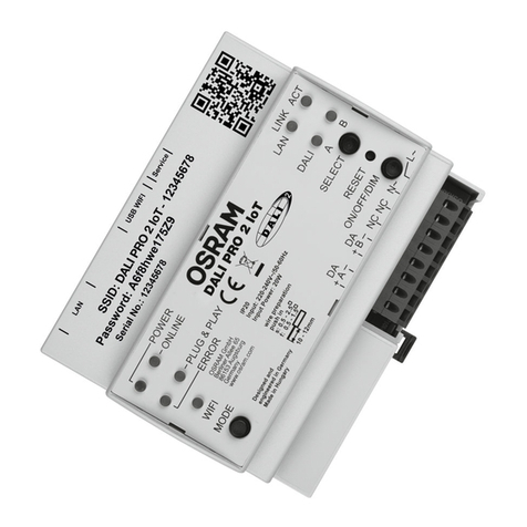
Osram DALI Professional Controller-4 User manual

DALI Professional
Controller-4
Control unit
Operating instructions


3
Contents

4
Safety
General instructions
Safety instructions
WARNING!
CAUTION!

5
Description
Purpose and application
Conguration
Design
Connections
Pushbutton

6
LED displays
„DALIPORT“ (G): Status of the DALI A, B, C, D lines:
LED Meaning
„RELAY“ (H): Status of the relay outputs K1, K2, K3, K4
LED Meaning
LEDs for status display of the control unit (K)
LED Meaning
LED Meaning
LED Meaning

7
LED Meaning
LED Meaning
G JFE K
H
D
ABC

8
Installation
Fasten control unit
Step Task

9
Connecting the control unit
Safety instructions
WARNING!
WARNING!
CAUTION!

10
Preparing the wiring
10 - 12 mm
Relays
Relays Connection to K1, K2, K3, K4
Number of pushbuttons and sensor couplers
à
Pushbutton

11
Connection diagram
L1
L2
L3
N
PE
A1
DA
DA
220
-240 V
21
22
23
24
25
26
27
28
A2
DA
DA
220
-240 V
21
22
23
24
25
26
27
28
A3
DA
DA
220
-240 V
21
22
23
24
25
26
27
28
F3
F2
DALI Professional
DA
DA
DA
DA
K1 K2 K4K3 +-+-+-+-
A
DA
B
DA
C
DA
D
DA NC PE N L
DALI PROFESSIONAL
CONTROLLER-4
4
A62
DA
DA
220
-240 V
21
22
23
24
25
26
27
28
A63
DA
DA
220
-240 V
21
22
23
24
25
26
27
28
A64
DA
DA
220
-240 V
21
22
23
24
25
26
27
28
DALI Professional
DA
DA
DA
DA
4
F1
DALI Professional
DA DA
A B C D
DALI Professional
DA DA
A B C D
DALI ECG
DALI ECG
DALI ECG
Sensor coupler
Light and
motion sensor
DALI ECG
Pushbutton coupler
Pushbutton coupler
DALI ECG
Sensor coupler
Light and
motion sensor
DALI ECG
Analog wiring
of the B, C and D circuits
Sensor
Sensor

12
System overview
1 2 3 4 5 6 7 8 64
1 2 3 4 5 6 7 8 64
1 2 3 4 5 6 7 8 64
1 2 3 4 5 6 7 8 64
USB
Light and
motion sensor
Sensor
coupler
Pushbutton
coupler

13
Operation
Basic state
à
à
à
à
Construction Site mode
Procedure (example)
Pushbutton
SELECT
Pushbutton:
ON/OFF/DIM
State/change

14
Pushbutton
SELECT
Pushbutton:
ON/OFF/DIM
State/change

15
Plug & Play mode
Symbols
Principle
max.
max.
5 min
Pushbutton pressed?
Pushbutton pressed?
Luminaires
manually switched off
before max. 30 s?
Motion?
Luminaire
OFF
Luminaire
ON
Luminaire
ON
yes yes
yes
yes
no no
no
no Motion? no
yes

16
Systems RESET
Operation
2x
max
1 2 3
< 30 s
1 2 3
1 2 3
A
B
...
> 30 s
2x
max
1 2 3
< 30 s
1 2 3
1 2 3
A
B
...
> 30 s
Further operating functions
Ofine mode (power supply via the USB interface)
Step Task
à
à
à

17
Behaviour after a power failure
In the Construction Site or Plug & Play mode
With previous conguration by means of the DALI Professional software

18
Appendix
Technical data
Applicable standards
Notes
Address Circuit Name Type Comments

Address Circuit Name Type Comments

OSRAM GmbH
40083214789488
Address Circuit Name Type Comments
Table of contents
Other Osram Control Unit manuals

Osram
Osram DALI BC ADVANCED RI User manual

Osram
Osram WSLC User manual

Osram
Osram DALI EN-DB-1L-GB2 User manual

Osram
Osram Touch DIM RC User manual
Osram
Osram LUXeye Sense 10A BT User manual
Osram
Osram traxon e:cue LCE-mx User guide

Osram
Osram CLM User manual

Osram
Osram DALI PRO 2 IoT User manual

Osram
Osram HUBSENSE User manual

Osram
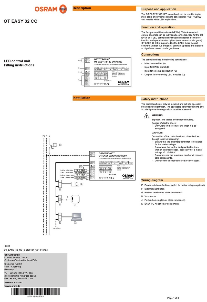
Osram OT EASY 32 CC User manual
Popular Control Unit manuals by other brands

Bosch
Bosch MU 100 EMS installation instructions

Valve Concepts
Valve Concepts 5500 Installation, operation and maintenance manual

ARAG
ARAG IBX100 4679004 Installation, use and maintenance guide

Jasco
Jasco 45602 instructions

Bastl Instruments
Bastl Instruments Little Nerd Assembly guide

Grundfos
Grundfos CIM 500 manual