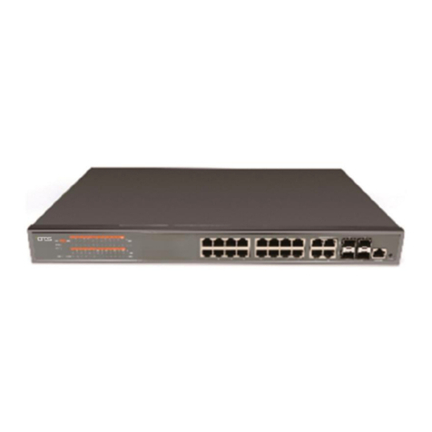
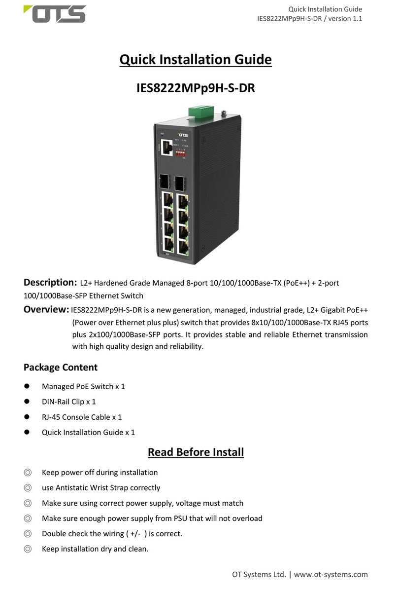
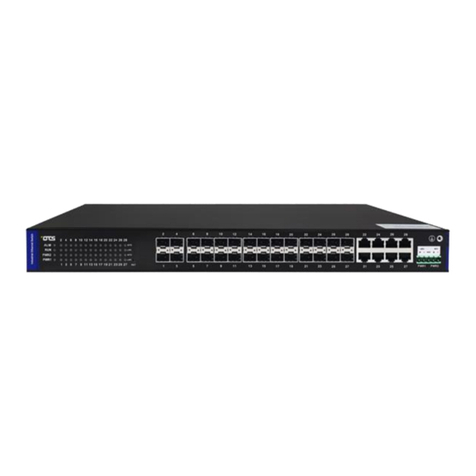
OTS ET42202XM-S-PD User manual

ET42202XM-S-PD
L2+ Managed 20-port 100/1000Base-FX SFP + 4-port 10/100/1000Base-TX or 100/1000Base-FX SFP
Combo + 4-port 1000/10GBase-FX SFP Optical Ethernet Switch, AC + DC power inputs
1
1. Introduction
This installation manual describes the installation procedures of the L2+ Managed 20-port
100Base-FX/1000Base-X SFP + 4-port 10/100/1000Base-T or 100/1000Base-FX SFP Combo + 4-port
1/10GBase-FX SFP Optical Ethernet Switch with AC + DC inputs. This is the Switch of choice to suit for
supporting standard industrial applications. Managed switches are easily to prioritize, partition and organize
user’s network and provide reliable and good quality services
2. Environmental Aspects
This is the perfect choice to work in within a constrained space that between a harsh temperature extremes of
-20∘C and 60∘C inclusively for the ET42202XM-S-PD. The ET42202XM-S-PD Fiber Switch is broad
portfolio of easy-implement managed Ethernet switches. Models include with 24 ports of 1G SFP and 4-port
10G SFP connectivity, providing ideal flexibility to design suitable network infrastructure for business
requirement. Besides, these switches are easy to deploy and configure, providing stable and quality
performance network services your business needs.
3. Unpacking. Inspecting and storing
3.1 Removing the transport packaging
Examine the delivered product thoroughly to ensure that the product has not been damaged during
transportation. Remove the transport packing carefully without any force.
3.2 Identifying the product
Locate the order number of the delivered product from the label of the on top of the packing box and check
against the ordering information to verify that the received product is correct.
3.3 Check the delivery product
Check that all items are included in the delivery in accordance with the delivery documents.
3.4 Inspecting the product
Check the product carefully to see if any damage occurred during the transportation. Notify the supplier
immediately if there are any discrepancies or damage in relation to the delivery documents.
3.5 Storing
If the product is stored before installation, it must be done with the original transport packaging in a dry
and dust free environment.

ET42202XM-S-PD
L2+ Managed 20-port 100/1000Base-FX SFP + 4-port 10/100/1000Base-TX or 100/1000Base-FX SFP
Combo + 4-port 1000/10GBase-FX SFP Optical Ethernet Switch, AC + DC power inputs
2
3.6 Packaging content and product description
Package Content
1. ET42202XM-S-PD L2+ Managed 20-port 100Base-FX/1000Base-X SFP + 4-port 10/100/1000Base-T or
100/1000Base-FX SFP Combo + 4-port 1/10GBase-FX SFP Optical Ethernet Switch with AC + DC inputs x 1
2. Rack Mount Bracket
3. Screws (for Bracket)
4. Four adhesive rubber feet
5. AC Power Cord
6. RS232 DB9 to DB9 cable x 1
7. Quick Installation Guide x 1
4. Mounting & Installation
4.1 Checking the environmental conditions and mounting space
Avoid installing the Ethernet Switch in an environment of dusty and damp, rapid temperature variations,
and similar extreme conditions.
4.2 Check that the mounting space is sufficient
Sufficient space is needed at the front of the Switch to allow access to the UTP at the front.
a)Rack-mount installation
Step1. Attach the brackets to the device using the screws provided in the Mounting Accessory.
Attaching the Brackets
Step2. Mount the device in the rack (Via Optional Rack-Mount kit), using our rack-mounting
screws (not provided). Be sure to secure the lower rack-mounting screws irst to prevent the

ET42202XM-S-PD
L2+ Managed 20-port 100/1000Base-FX SFP + 4-port 10/100/1000Base-TX or 100/1000Base-FX SFP
Combo + 4-port 1000/10GBase-FX SFP Optical Ethernet Switch, AC + DC power inputs
3
brackets being bent by the weight o the switch.
Installing the switch in a Rack
Step3. I installing a single switch only, turn to “Connection to a Power Source” at the end o
this chapter.
Step4. I installing multiple switches, mount them in the rack, one below the other, in any
order.
b)Desktop of Shelf Mounting.
Step1. Attach the our adhesive rubber eet to the bottom o the irst switch.
Attaching the adhesive rubber feet
Step2. Set the device on a lat sur ace near an AC power source, making sure there are at

ET42202XM-S-PD
L2+ Managed 20-port 100/1000Base-FX SFP + 4-port 10/100/1000Base-TX or 100/1000Base-FX SFP
Combo + 4-port 1000/10GBase-FX SFP Optical Ethernet Switch, AC + DC power inputs
4
least two inches o space on all sides or proper air low.
Step3. I installing a single switch only, go to “Connecting to a Power Source” at the end o
this Chapter.
Step4. I installing multiple switches, attach our adhesive eet to each one. Place each
device squarely on top o the one below, in any order.
4.3 Installing the SFP Transceiver Module
You can choose the appropriate SFP module from our SFP selection list for the ET42202M-S-PD. To
install the SFP module, follow the procedures as below:
a. On the front panel, slide the SFP module all the way into the SFP
receptacle (Port) until it is securely locked.
b. Plug in the optical fiber (1/2 core) to the LC connector(s) of the
SFP.
Ground Connecting
ET42202XM-S-PD
must be properly grounded for optimum system performance.
5. Start-up
a. Connect the Ethernet port of the ET42202XM-S-PD to a PC or network device with a network cable.
b. Insert the appropriate SFP module into the SFP port. Connect the fiber cable from the remote device to the LC
connector of the SFP of the Switch (near end).
c. After the devices are powered on, the PWR indicators will all be on. If the indicators are not on, check the
power supply connection.
d. After all cables are correctly connected, the indicators will be lit as per port status LEDs.
6. Technical Data
DC Power Connecting
You can plug or remove DC power cable through the DC terminal block rom external 48VDC DC power

ET42202XM-S-PD
L2+ Managed 20-port 100/1000Base-FX SFP + 4-port 10/100/1000Base-TX or 100/1000Base-FX SFP
Combo + 4-port 1000/10GBase-FX SFP Optical Ethernet Switch, AC + DC power inputs
5
source.
Step1.Insert the DC cable plug directly into the DC terminal block located at the ront o the switch.
Step2.Plug the other end o the cable into an external DC power source.
Step3.Check the ront-panel LEDs as the device is powered on to be sure the POWER LED is lit. I not,
check that the power cable is correctly plugged in.
AC Power Connecting
You can plug or remove AC power cord through the AC socket rom AC power source.
Step1. Insert the power cable plug directly into the AC Socket located at the back o the switch.
Step2. Plug the other end o the cable into a grounded, 3-Pin, AC power source.
Step3. Check the ront-panel LEDs as the device is powered on to be sure the POWER LED is lit. I not,
check that the power cable is correctly plugged in.
W
ARNING
:
For International use, you may need to change the AC
line cord. You must use a line cord set that has been approved or
the socket type in your country.
Ethernet Interface Connecting (RJ45 Ethernet)
To ensure proper operation when installing the switch into a network, make sure that the current
cables are suitable or 100BASE-TX or 1000BASE-T operation. Check the ollowing criteria against
the current installation o your network:
◆
Cable type: Unshielded twisted pair (UTP) or shielded twisted pair (STP) cable with RJ-45
connectors; Category 5 or Category 5e with maximum length o 100 meters is recommend
100BASE-TX, and Category 5e or 6 with maximum length o 100 meters is recommend or

ET42202XM-S-PD
L2+ Managed 20-port 100/1000Base-FX SFP + 4-port 10/100/1000Base-TX or 100/1000Base-FX SFP
Combo + 4-port 1000/10GBase-FX SFP Optical Ethernet Switch, AC + DC power inputs
6
1000BASE-T.
◆
Protection rom radio requency inter erence emissions.
◆
Electrical surge suppression.
◆
Separation o electrical wires and data based network wiring.
◆
Sa e connections with no damaged cables, connectors or shields
Console Connection
Serial Cable Wiring
N
OTE
:it does not support cross cable for console port
Connect & Login to ET42202XM-S-PD Switch
1. Connecting PC to ET42202XM-S-PD Ethernet port (RJ45 Ethernet port).
2. Factory default IP: 192.168.2.1
3. Login with default account and password.
Username: admin
Password: System
A ter the managed switch has been inished con iguration in the CLI via the switch’s serial inter ace,
you can browse it. For instance, type http://192.168.2.1 in the address row in a browser, it will show
the ollowing screen and ask you inputting username and password in order to login and access
authentication. The de ault username is “admin” and password is "System". For the irst time to
use, please enter the de ault username and password, and then click the Login button. The login
process now is completed.

ET42202XM-S-PD
L2+ Managed 20-port 100/1000Base-FX SFP + 4-port 10/100/1000Base-TX or 100/1000Base-FX SFP
Combo + 4-port 1000/10GBase-FX SFP Optical Ethernet Switch, AC + DC power inputs
7
Front of the Switch
Port and System Status LEDs
The ET42202XM-S-PD switch includes a display panel for system and port indications that simplify installation
and network troubleshooting. The LEDs, which are located on left hand side of the front panel for easy viewing.
Details are shown below and described in the following tables.
Port Status LEDs
LED Condition Status
P1-P24 TP
Link/Act/Speed Green/ Amber
Lit Green when TP link on 1000Mbps speed.
Lit Amber when TP link on 10/100Mbps speed.
Blinks when any tra ic is present.
P25-P26 SFP+
Link/Act/Speed Green/ Amber
Light Green when SFP+ link up 10Gbps speed.
Light Amber when SFP+ link up 1Gbps speed.
Blinks when any tra ic is present.

ET42202XM-S-PD
L2+ Managed 20-port 100/1000Base-FX SFP + 4-port 10/100/1000Base-TX or 100/1000Base-FX SFP
Combo + 4-port 1000/10GBase-FX SFP Optical Ethernet Switch, AC + DC power inputs
8
System Status LED
SYSTEM LED Condition Status
PWR AC Green Light when power on
PWR DC Green Light when power on
SYS Green
Blinking when system is booting;
Lit when system is coming up.
ALARM Red Always o ; until any message about system
error turn the light on.

ET42202XM-S-PD
L2+ Managed 20-port 100/1000Base-FX SFP + 4-port 10/100/1000Base-TX or 100/1000Base-FX SFP
Combo + 4-port 1000/10GBase-FX SFP Optical Ethernet Switch, AC + DC power inputs
9
Dimensional Drawing of the Product (Unit: mm)
Manual Earth Green manual is available on our website www.ot-systems.com
Table of contents
Other OTS Switch manuals

OTS
OTS IES16242MPpH-S-DR User manual

OTS
OTS ET8222PpH-S-DR User manual

OTS
OTS IES8242MPpH-S-DR User manual

OTS
OTS IES24242MPp-S User manual

OTS
OTS IES8242MPpH-S-DR User manual

OTS
OTS IES24242MPpH-S User manual

OTS
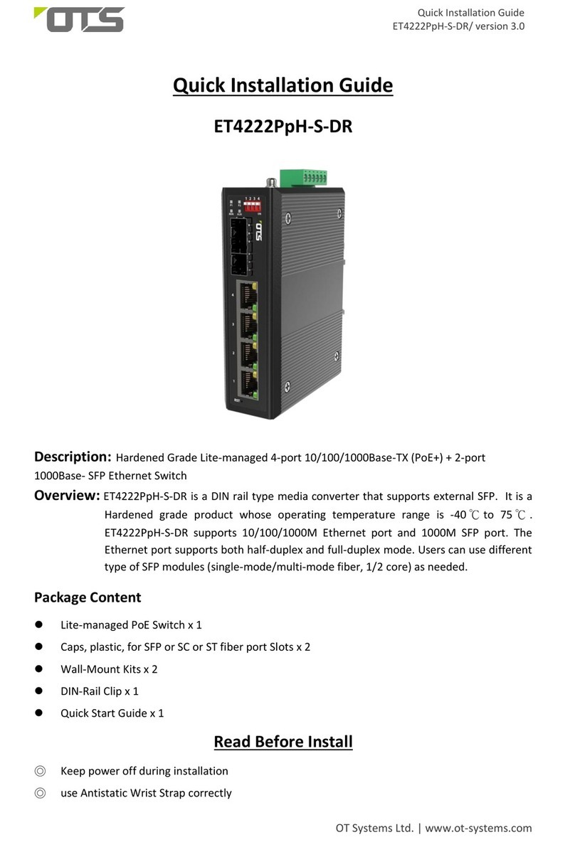
OTS ET4222PpH-S-DR User manual

OTS
OTS ET2212Pp-S-DR User manual
OTS
OTS IES8222MPp9H-S-DR User manual

OTS
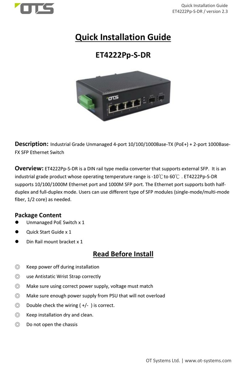
OTS ET4222Pp-S-DR User manual

OTS
OTS ET2212PpH-S-DR User manual

OTS
OTS IES82162XMH-S-RP User manual

OTS
OTS ET4222Pp9H-S-DR User manual
OTS
OTS IES8242MPp9H-S-DR User manual

OTS
OTS EC10200Pp User manual

OTS
OTS ET8222PpH-S-DR User manual
OTS
OTS IES82162MH-S-RP User manual
OTS
OTS IES8222MPpH-S-DR User manual

OTS
OTS ET2212Pp-S-DR User manual
OTS
OTS ET4222Pp9H-S-DR User manual