manuals.online logo
Brands
  1. Home
  2. •
  3. Brands
  4. •
  5. Overland Tandberg
  6. •
  7. Control Unit
  8. •
  9. Overland Tandberg NEOxl 40 User manual

Overland Tandberg NEOxl 40 User manual

*10400849001*
10400849-001 ©2018 Overland Storage, Inc. Page 1 of 6
NEOxl®40 Tape Library
Spare Expansion Module Instructions
This document describes how to remove and replace an existing
Expansion Module in a NEOxl 40 (3U) tape library from
Overland Storage.
WARNING: To reduce the risk of electric shock or damage to
equipment, always remove any power cords while working with
the library.
WARNUNG: Um das Risiko eines elektrischen Schlags oder
Schäden am Gerät zu vermeiden, ziehen Sie stets den
Netzstecker, bevor Sie an der Einheit arbeiten.
AVERTISSEMENT: Pour réduire le risque de choc électrique
ou endommagement de l'équipement, retirez toujours les
cordons électriques en travaillant avec l'appareil.
CAUTION: While working with the library, observe standard
Electrostatic Discharge (ESD) precautions to prevent damage
to micro-circuitry or static-sensitive devices.
Special Handling Notice
Each NEOxl 40 Expansion Module weighs more than 44
lbs (20 kg) without drives or tapes and more than 77 lbs
(35 kg) with three tape drives and 40 tapes.
Before moving or lifting the Expansion Module, remove
the tape magazines and drives to reduce the weight.
Overview
To replace an existing Expansion Module, the steps include:
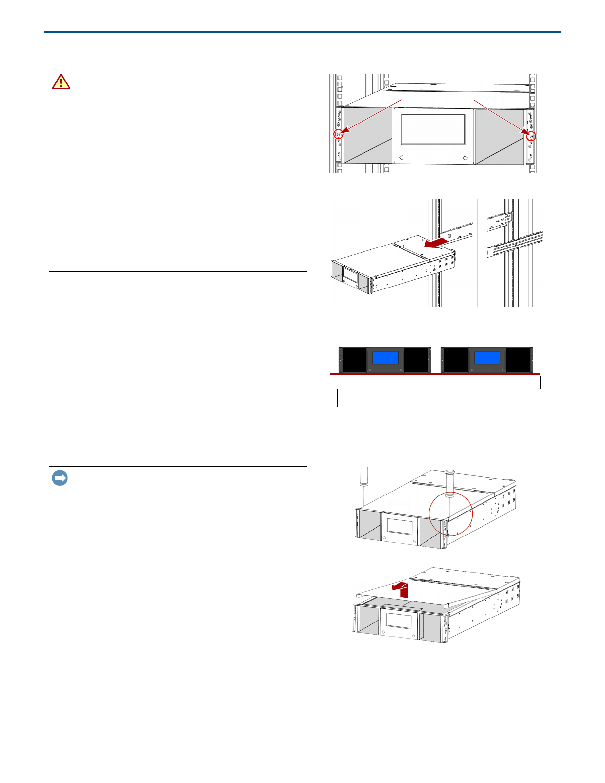
1. After removing the tape magazines and drives, remove the
old Expansion Module from the rack.
2. If necessary, transfer the top or bottom cover from the old
Expansion Module to the new one.
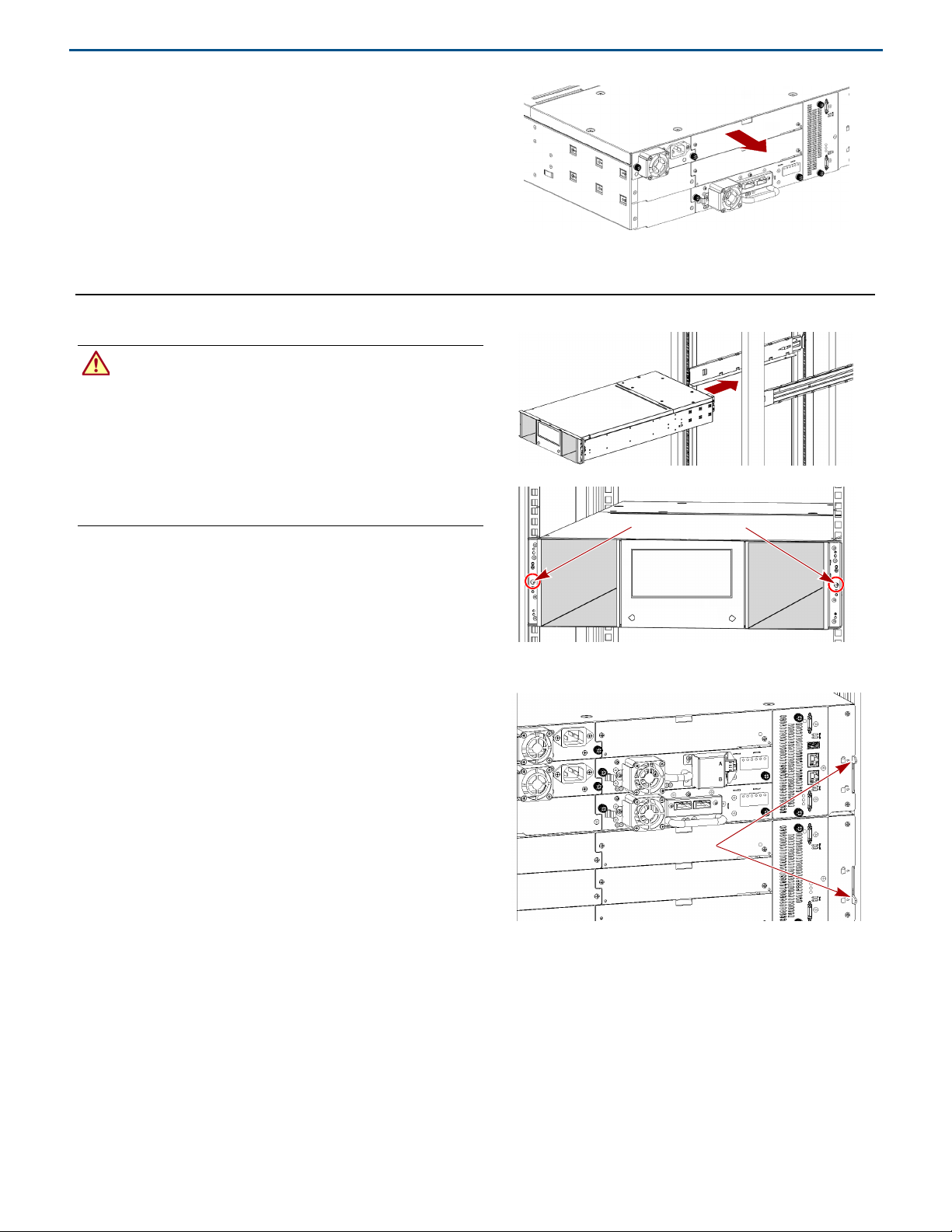
3. Move the power supplies, DC-DC board, and controller
from the old Expansion Module to the new one.
4. Install the new Expansion Module in the rack and align
the module with the library.
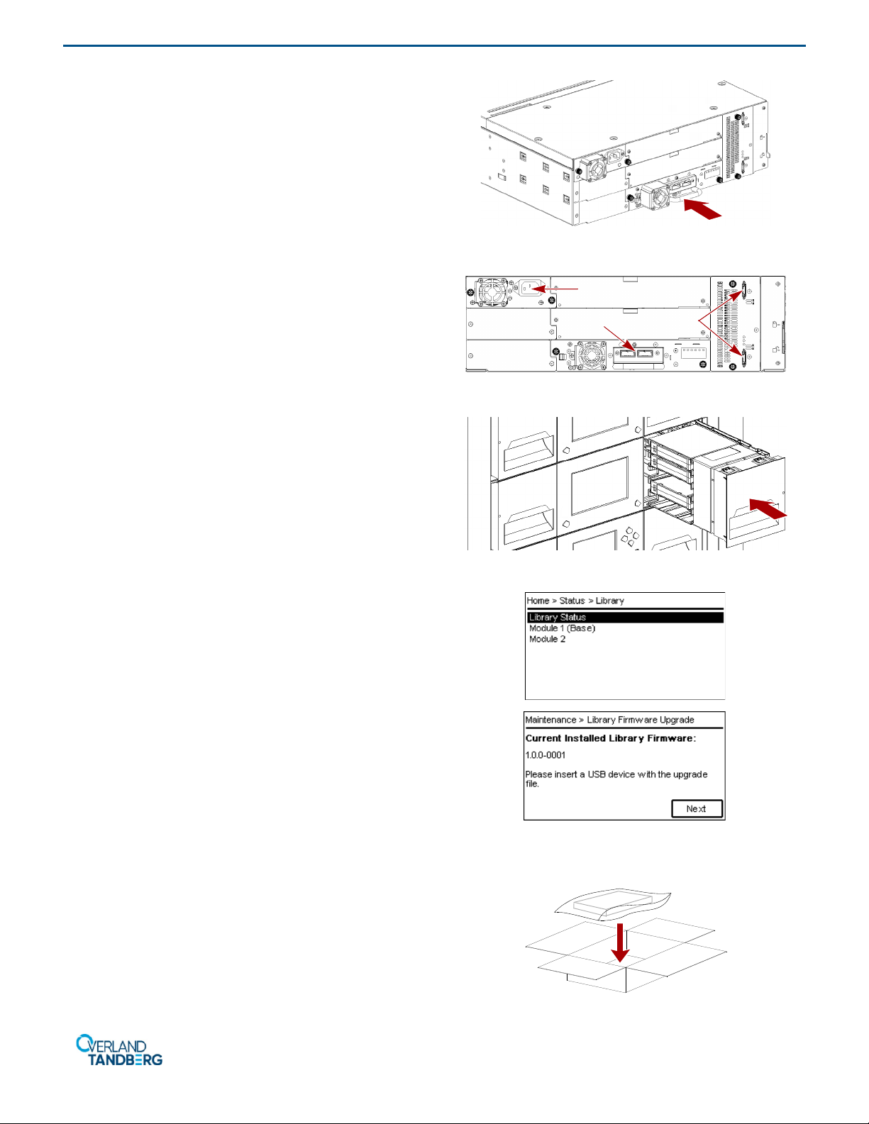
5. Reinstall tape magazines and drives into the new module.
6. Reconnect the cables and verify the installation.
You will need a small flat head or Torx screwdriver and a #2
Phillips screwdriver.
Prepare the Library
Remove Tape Magazines
Make sure all activities are completed and all backup software
services are stopped. Remove the tape magazines from the
Expansion Module being replaced.
NOTE: If a magazine needs to be removed when the power to the
device is off, refer to the Manual Release Process below.
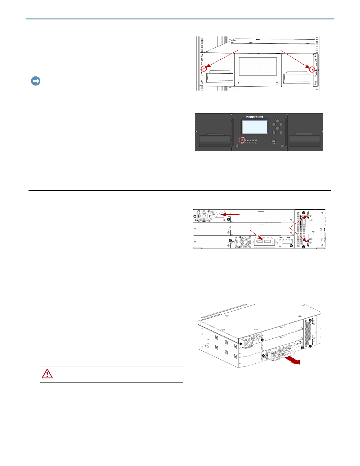
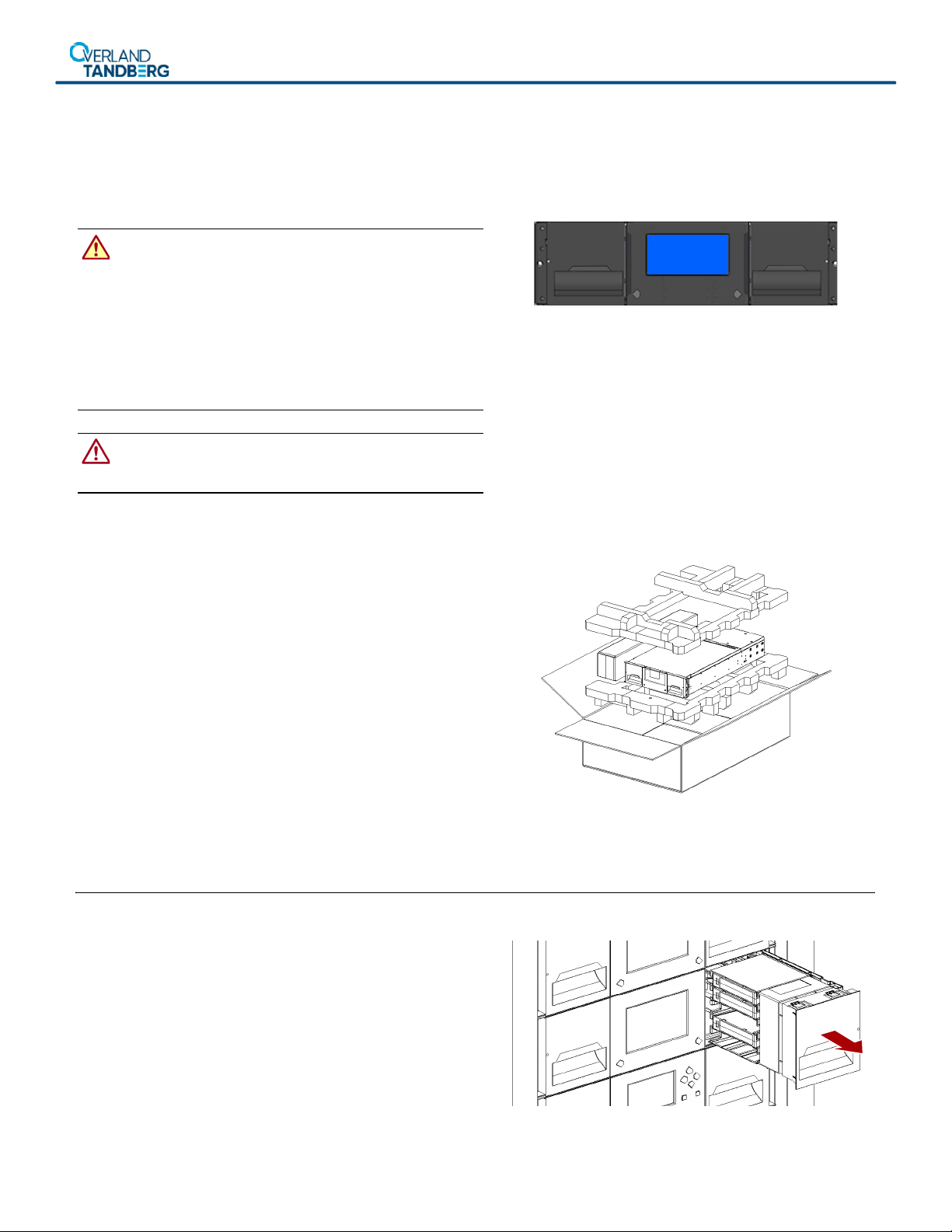
1. From the OCP or RMI, first select the right magazine and
then select
Open Magazine
.
2. Using the right magazine access handle and supporting
it underneath, pull the magazine out of the library.
3. Place the magazine on a secure surface.
4. Repeat Steps 1–2 for the left magazine.
NEO Spare Expansion Module Instructions
10400849-001 ©2018 Overland Storage, Inc. Page 2 of 6
Manual Release Process
If power is not available on the Expansion Module, the
magazines can be released using the manual release hole on
the side of the magazine. Insert a small flat head screwdriver
or Torx driver into the appropriate magazine release hole and
gently push the tab in.
IMPORTANT: Do not continue to exert force once you
encounter resistance. Doing so can damage the device.
Power Off Library
If still running, power off the library from the Base Module
front panel by pressing and holding down the power button for
three (3) seconds.
NOTE: If the library does not perform a soft shutdown, press and
hold the power button for 10 seconds.
Verify that the Robotic Assembly is in its parked position and
that all host processes are idle.
Remove Old Expansion Module
Remove Cables
Disconnect all cables and cords, noting where they connect.
1. If power supplies exist, unplug any AC power cords (1).
2. Remove the expansion interconnect cables (2) from
the Expansion Module and any modules to which it is
connected.
NOTE: Completely removing the expansion interconnect cables
from the modules prevents damaging the cables during module
removal and replacement.
3. If the Expansion Module has drives, label and remove all
the SAS/FC cables (3) from them.
Remove Tape Drives
NOTE: Because the library tracks the drive locations and issues
events if the drives aren't in the expected locations, label the drives
so they can be reinstalled in the same drive bays.
1. Use your fingers to loosen the blue thumbscrews on the
tape drive.
2. While supporting the bottom of the drive, pull straight
back on the tape drive handle to remove it from the
module.
CAUTION: Support the bottom of the tape drive when
removing it to avoid damaging any internal connections.
3. Place the drive on a secure ESD surface.
4. Repeat Steps 1–3 for any additional drives.
Manual Release Holes
1
32
NEO Spare Expansion Module Instructions
10400849-001 ©2018 Overland Storage, Inc. Page 3 of 6
Remove Expansion Module from Rack
WARNING: To avoid injury, it is recommended that a
mechanical lifter (or at least two people) be used for rack
installation or removal. Use care during rack installation or
removal to avoid accidentally tilting or tipping the rack, causing
damage or personal injury.
WARNUNG: Um Verletzungen zu vermeiden, empfehlen wir zur
Rack-Installation oder -Deinstallation die Nutzung einer
mechanischen Hebehilfe (oder mindestens zwei Personen).
Seien Sie vorsichtig bei der Rack-Installation oder -Entnahme,
um ein versehentliches Kippen des Racks zu vermeiden und
das Rack nicht zu beschädigen bzw. sich selbst zu verletzen.
AVERTISSEMENT: Afin d’éviter des blessures pendant
l’installation, il est recommande d’utiliser un monte-charge (ou
au moins deux personnes) pour élever ou aligner l’module.
Faites attention lorsque vous insérez ou retirez l’module d’un
support, pour empêcher le déversement accidentel de la
crémaillère causant des dommages et des blessures.
1. From the front, use a #2 Phillips screwdriver to loosen the
recessed screws two full turns on the Expansion Module
and the adjacent modules.
2. From the back of the library, unlock the alignment
mechanisms connecting the Expansion Module with the
adjacent modules.
3. Carefully slide the module out onto a mechanical lifter.
4. Place the module on a secure ESD surface.
5. Unpack the new Expansion Module and place in on the
surface next to the old module.
6. Remove the tape magazines from the new unit using the
Manual Release Process.
Move Covers
IMPORTANT: When replacing an Expansion Module in either
the top or bottom position, you must move the cover from the
old Expansion Module to the new one.
To move a top cover:
1. At the old Expansion Module, unlock the top cover by
pushing two small screwdrivers down and inward in
both slots.
2. Lift the top cover front edge by about 4.75 in. (12cm) and
pull the cover gently forward to disengage from the pivot
point at the module center.
3. At the new Expansion Module, with the cover at the same
angle, reengage the rear of the cover at the pivot point.
4. Lower the front of the top cover until the latches engage
on both sides.
Recessed Screws
NEO Spare Expansion Module Instructions
10400849-001 ©2018 Overland Storage, Inc. Page 4 of 6
To move a bottom cover:
1. Place both Expansion Modules upside-down.
2. At the old Expansion Module, insert a small flathead or
Torx screwdriver into the release hole and slide it about
1/4 in. (4mm) sidewards to unlock the spring loaded lock.
3. Raise the cover front end by about 4 in. (10cm) and
gently pull it forward to disengage from the pivot point at
module center and remove.
4. At the new Expansion Module, with the cover at the same
angle, reengage the rear of the cover at the pivot point.
5. Lower the front of the cover until the latch engages.
Move Power Supplies
NOTE: If any power supplies are installed, they need to be moved
to the new Expansion Module.
1. At the new Expansion Module, remove the appropriate
power supply covers.
2. At the old Expansion Module, loosen the two blue
captive thumbscrews with your fingers on the power
supply.
3. While supporting the bottom, pull the power supply
straight back to remove it from the module.
4. At the new Expansion Module, position the power supply
onto the alignment rails.
5. Slide the power supply into the module until it is flush
with the back panel of the module.
6. Tighten the thumbscrews with your fingers to secure it.
7. If necessary, repeat these steps for a redundant power
supply.
8. Install the removed power supply covers on the old
Expansion Module.
Move Controller
1. At the old Expansion Module, loosen the two blue
captive thumbscrews on the controller and slowly
remove it from the Expansion Module, setting it aside.
2. If a drive power board is installed, also move it:
a. Push down the drive power board latch to release it.
b. Slowly slide the drive power board out of the module.
c. At the new Expansion Module, position the drive power
board onto the alignment rails.
d. Slide the drive power board in until seated firmly.
e. Push the board latch up until it snaps into place.
3. At the new Expansion Module, position the controller on
the alignment rails and slide it in until it is flush with the
back panel of the module.
4. Tighten the thumbscrews with your fingers to secure it
to the module.
NEO Spare Expansion Module Instructions
10400849-001 ©2018 Overland Storage, Inc. Page 5 of 6
Move Drive Bay Covers
NOTE: If any drive bays on the old Expansion Module have covers
installed, they need to be moved to the new Expansion Module.
Remove the drive bay covers from the old Expansion Module
and install them in the same bays on the new Expansion
Module.
Install New Expansion Module
Insert the Module in Rack
WARNING: To avoid injury, it is recommended that a
mechanical lifter (or at least two people) be used for rack
installation or removal.
WARNUNG: Um Verletzungen zu vermeiden, empfehlen wir zur
Rack-Installation oder -Deinstallation die Nutzung einer
mechanischen Hebehilfe (oder mindestens zwei Personen).
AVERTISSEMENT: Afin d’éviter des blessures pendant
l’installation, il est recommande d’utiliser un monte-charge (ou
au moins deux personnes) pour élever ou aligner l’module.
1. Using the mechanical lifter, position the module in front,
aligned with the rack rails.
2. Slide the module onto the rail flanges and into the rack.
3. Tighten the recessed screws only one turn to hold it.
Aligning and Connecting the Module
Aligning the Expansion Module with the library ensures that
the robot can move freely between the modules.
NOTE: The library will not operate unless the alignment
mechanism is in the locked position (except the bottom module).
1. At the back of the library, using the alignment lock
lever, align and lock the new Expansion Module to the
modules to which it connects.
If you encounter resistance, adjust the upper module so
that the alignment mechanism pin moves into the mating
hole in the lower module.
2. Verify that, for the lowest module in the library, its
alignment mechanism is in the unlocked position.
3. From the front of the library, tighten the Phillips screws
on both the Expansion Module and the adjacent modules
to secure them all to the rack.
Recessed Screws
Alignment Locks
http://support.overlandstorage.com
You can get additional technical support on the Internet at the Overland Storage Support web page, or by contacting Overland Storage using
the information found on the Contact Us page on our web site.
NEO Spare Expansion Module Instructions
10400849-001 ©2018 Overland Storage, Inc. Page 6 of 6
Reinstall Tape Drives
If any tape drives were in the old Expansion Module:
1. Holding a tape drive by the handle and supporting it
from the bottom, position it on the alignment rails.
2. Slowly slide the tape drive into the drive bay until it is
flush with the back of the library.
3. Finger-tighten the blue captive thumbscrews to secure.
4. Repeat Steps 1–3 for any additional tape drives.
Reattach Cables and Cords
1. Reconnect the expansion interconnect cables (2) from
the Expansion Module to the adjacent modules.
2. If the Expansion Module has drives, reconnect all the
tape drive cables to the same ports (3) on the same
drives.
3. If power supplies exist, replug the AC power cords (1) in.
Reinstall Tape Magazines
Reinstall the previously removed tape magazines into the new
Expansion Module.
1. Using the magazine access handle and supporting it
underneath, position the magazine on the alignment rails.
2. Slide the magazine into the module.
3. Repeat Steps 1–2 for the other magazine.
4. Install the empty tape magazines in the old unit.
Verifying the Installation and Configuration
Power on the library and check the following:
•Verify that the library powers on and initializes correctly,
and that the status is Ready.
•From the OCP or RMI, verify that the new Expansion
Module is visible.
•Check the library configuration settings related to the
additional storage slots, mailslots, and tape drives.
Update if necessary.
The Expansion Module operates using the existing library
firmware. It is recommended that you always update the
library to the latest firmware version. You can update
firmware from the RMI or the OCP
Maintenance > Library
Firmware Upgrade
screen.
Return Replaced Part to Overland
For warranty replacements:
1. Place the old Expansion Module in the box that the new
replacement Expansion Module came in.
2. Use the existing packing material to secure it in the box.
3. Use an RMA to return the part to Overland Storage.
For return shipping details and RMA number, go to:
http://docs.overlandstorage.com/return-instructions.
1
32

Other manuals for NEOxl 40

12

Other Overland Tandberg Control Unit manuals

Overland Tandberg NEOxl 40 User manual

Overland Tandberg

Overland Tandberg NEOxl 40 User manual

Overland Tandberg NEOxl 40 User manual

Overland Tandberg

Overland Tandberg NEOxl 40 User manual

Overland Tandberg NEOxl 40 User manual

Overland Tandberg

Overland Tandberg NEOxl 40 User manual

Overland Tandberg NEOxl 40 User manual

Overland Tandberg

Overland Tandberg NEOxl 40 User manual

Popular Control Unit manuals by other brands

BETAFPV Micro TX user manual

BETAFPV

BETAFPV Micro TX user manual

Bosch Rexroth M4-12 Repair manual

Bosch

Bosch Rexroth M4-12 Repair manual

EMME Core user guide

EMME

EMME Core user guide

Worx WA0863 manual

Worx

Worx WA0863 manual

GEA Aseptomag GD Operating	 instruction

GEA

GEA Aseptomag GD Operating instruction

Honeywell 4219 Installation and setup guide

Honeywell

Honeywell 4219 Installation and setup guide

TECSYSTEM NT538 WS instruction manual

TECSYSTEM

TECSYSTEM NT538 WS instruction manual

Aventics AS1 operating instructions

Aventics

Aventics AS1 operating instructions

Move Gateway Pro instruction manual

Move

Move Gateway Pro instruction manual

Phoenix Contact ILB BT ADIO MUX-OMNI datasheet

Phoenix Contact

Phoenix Contact ILB BT ADIO MUX-OMNI datasheet

Allen-Bradley 1732ES-IB16 user manual

Allen-Bradley

Allen-Bradley 1732ES-IB16 user manual

Siemens LOK16 Series manual

Siemens

Siemens LOK16 Series manual

Vortice NA 100 Instruction booklet

Vortice

Vortice NA 100 Instruction booklet

Agilent Technologies 83400 Series user guide

Agilent Technologies

Agilent Technologies 83400 Series user guide

Danfoss 088U0200 instructions

Danfoss

Danfoss 088U0200 instructions

Highcross ECM-RS2D Quick reference guide

Highcross

Highcross ECM-RS2D Quick reference guide

Siemens SIMATIC ET 200SP manual

Siemens

Siemens SIMATIC ET 200SP manual

Stalgast 430400 instruction manual

Stalgast

Stalgast 430400 instruction manual

manuals.online logo
manuals.online logoBrands
  • About & Mission
  • Contact us
  • Privacy Policy
  • Terms and Conditions

Copyright 2025 Manuals.Online. All Rights Reserved.