NEOxl 40 3U Expansion Module Quick Start Guide
10400896 ©2019 Overland-Tandberg Page 2 of 5
You will need a small flat head or Torx screwdriver and a #2
Phillips screwdriver.
Step 3
Power Off Library
If still running, power off the library from the Base Module
front panel by pressing and holding down the power button
for three (3) seconds.
NOTE: If the library does not perform a soft shutdown, press
and hold the power button for 10 seconds.
Verify that the Robotic Assembly is in its parked position
and that all host processes are idle.
Determine Installation Location
If library expansion was planned for, there should be space
for up to three Expansion Modules above and three
Expansion Modules below the Base Module.
When Expansion Modules are already in place, to eliminate
the steps needed to move covers, install the new rack rails in
the space above or below a current Expansion Module. Then
move the existing Expansion Module onto the new rails and
install the new Expansion Module onto the old rails.
See Chapter 1, “Supported Configurations,” in the NEOxl 40
Tape Library Administrator’s Guide for additional details.
Prepare the Modules
Depending on the new Expansion Module’s location, transfer
either the top or bottom module cover from the last module
in that location to the new Expansion Module.
NOTE: Installing the Expansion Module between modules does
not require moving a cover.
•If you are installing the Expansion Module below the
module stack, move the bottom module’s cover to the
Expansion Module.
•If you are installing the Expansion Module above the
module stack, move the top module’s cover to the
Expansion Module.
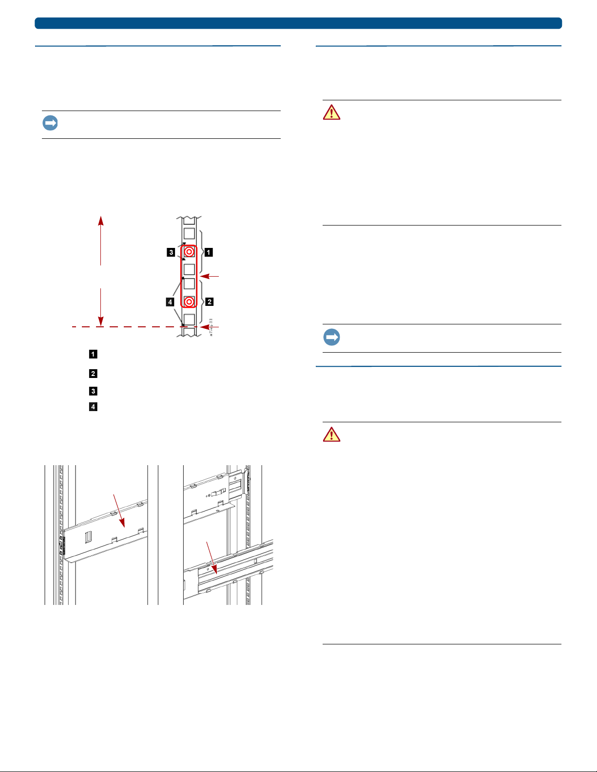
Install New
Move Up
New Rail
Old Rail
New Rail
Old Rail
Unit Here
IMPORTANT: A NEOxl tape library modular system can
support up to six Expansion Modules, three above and
three below. If you have not yet determined the architecture of
your configuration, refer to Chapter 1, “Supported
Configurations,” in the NEOxl 40 Tape Library Administrator’s
Guide for details.
1. Using the mechanical lifter, remove the existing
module from which you are removing the cover plate.
2. Place the removed module on a secure work table.
If you are removing the bottom cover, gently turn the
module over so you can access the bottom.
3. Place the new Expansion Module on the work table
next to the module you removed.
If you are adding the bottom cover, gently turn the
Expansion Module over so you can access the bottom.
4. Use a a small flathead or Torx screwdriver to unlock
the spring-loaded locks and release the cover.
•Top cover – Push two screwdrivers down and
inward about 1/4 in. (4mm) simultaneously in both
release slots.
• Bottom cover – Push a screwdriver down and
inward about 1/4 in. (4mm) in the release slot.
5. Raise the cover front end by about 4-5 in. (10-12cm),
gently pull it forward to disengage from the pivot point
at module center, and remove.
6. At the Expansion Module, install the cover.
Insert the rear of the cover into the center pivot point,
and then push the cover down until the spring locks
engage.
7. If the modules are upside down, gently turn them both
back over.
8. Using the mechanical lifter, reinstall the existing
module back into the rack in its same location.
Releases
Release
Top Cover
Bottom Cover