PI L-738 Series User manual

PI miCos GmbH, Freiburger Strasse 30, 79427 Eschbach, Germany
Phone +49 7634 5057-0, Fax +49 7634 5057-99, Email info@pimicos.com, www.pi.ws
MP183E
L
-738 / V-738 Precision XY Stage
User Manual
Version: 1.1.2
Date: 17-July-2019
This document describes the following precision
XY stage
s with 102 mm x 102 mm travel range:
L-738.051100:
With stepper motor, without encoder
L-738.051111:
With stepper motor and linear encoder,
sin/cos signal transmission
L-738.051112:
With stepper motor and linear encoder,
A/B quadrature signal transmission
L-738.053111:
With DC motor and linear encoder,
sin/cos signal transmission
L-738.053112:
With DC motor and linear encoder,
A/B quadrature signal transmission
L-738.053132:
With DC motor and rotary encoder,
A/B quadrature signal transmission
V-738.056111:
With linear motor and linear encoder,
sin/cos signal transmission

The following company names and brands are registered trademarks of
Physik Instrumente (PI) GmbH & Co. KG:
PI®, NanoCube®, PICMA®, PIFOC®, PILine®, NEXLINE®, PiezoWalk®, PicoCube®, PiezoMove®, PIMikroMove®,
NEXACT®, Picoactuator®, PInano®, NEXSHIFT®, PITOUCH®, PIMag®, PIHera, Q-Motion®
© 2019 Physik Instrumente (PI) GmbH & Co. KG, Karlsruhe, Germany. The text, photographs, and drawings in
this manual are protected by copyright. With regard thereto, Physik Instrumente (PI) GmbH & Co. KG reserves
all rights. The use of any text, images and drawings is permitted only in part and only when indicating the
source.
Original instructions
First printing: 17-July-2019
Document number: MP183E, MMa, Version 1.1.2
Subject to change without notice. This manual is superseded by any new release. The latest release is
available for download from our website (p. 5).

1About this Document 3
1.1 Objective and Target Group of this User Manual ...................................................... 3
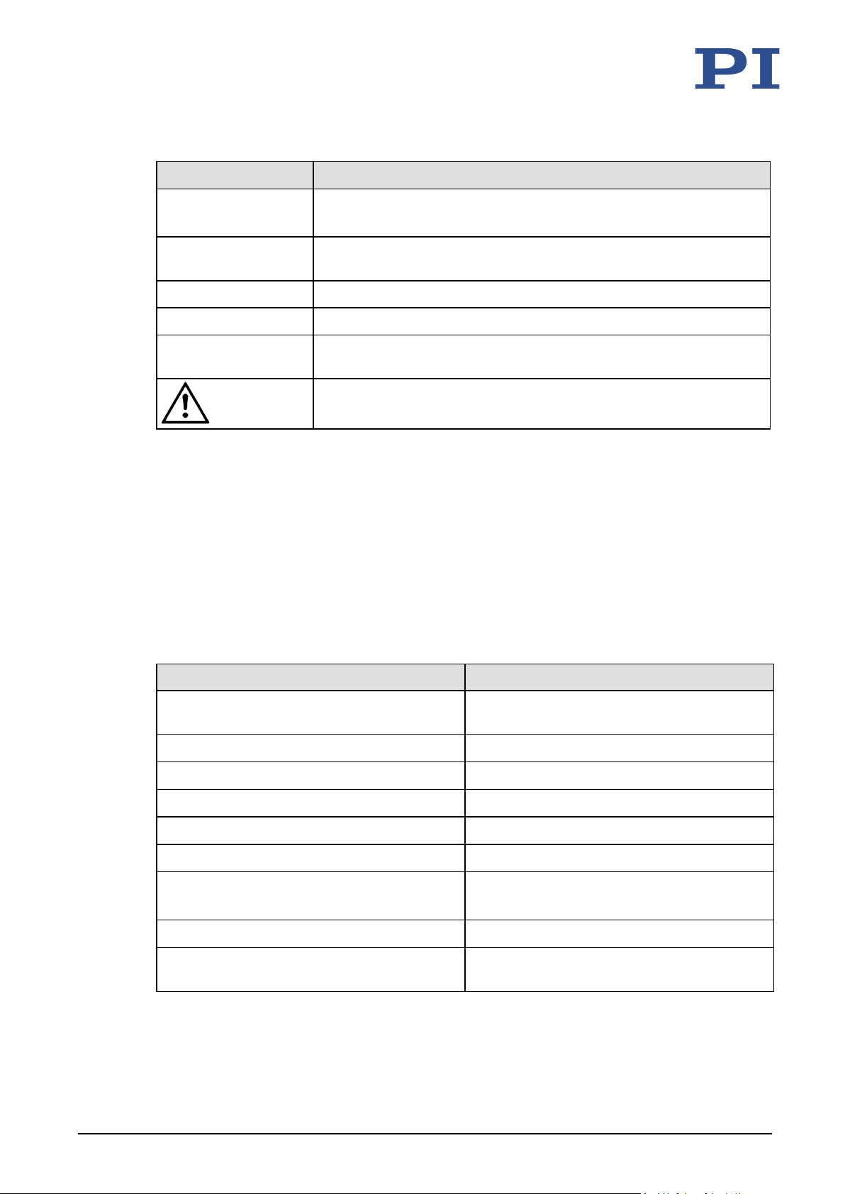
1.2 Symbols and Typographic Conventions...................................................................... 3
1.3 Pictures....................................................................................................................... 4
1.4 Other Applicable Documents ..................................................................................... 4
2Safety 5
2.1 Intended Use .............................................................................................................. 5
2.2 General Safety Instructions ........................................................................................ 5
2.3 Organizational Measures............................................................................................ 5
3Product Description 7
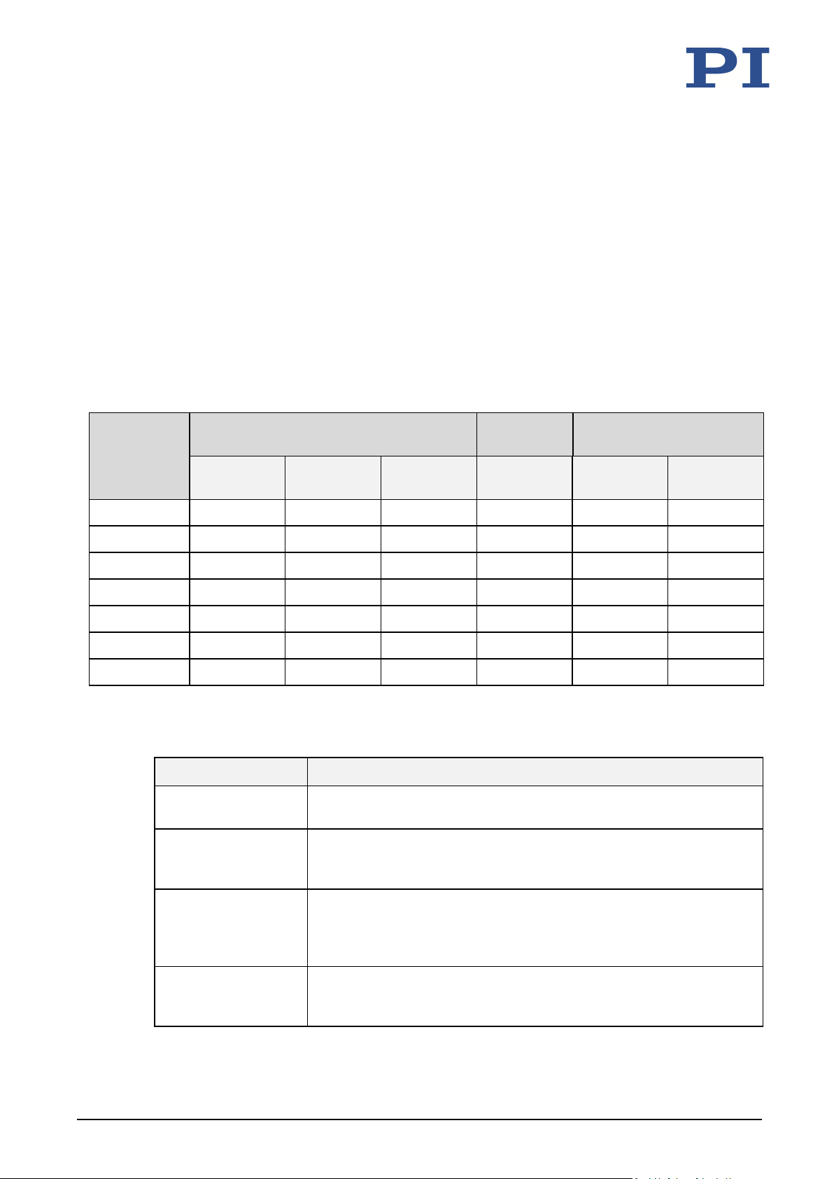
3.1 Model Overview ......................................................................................................... 7
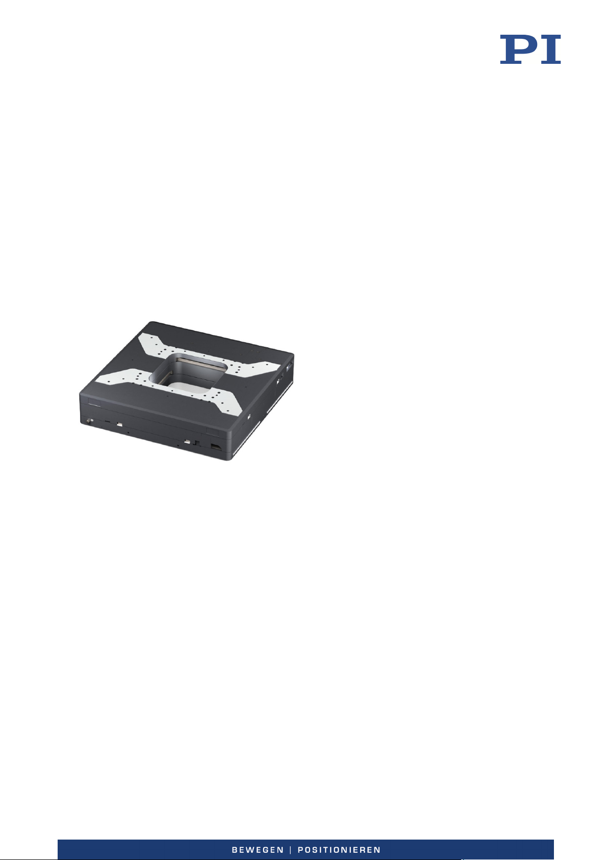
3.2 Product View .............................................................................................................. 8
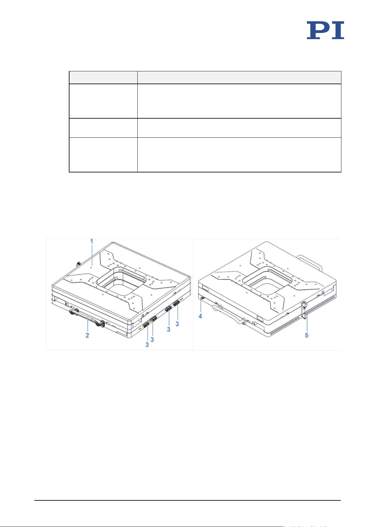
3.2.1 Important Components ................................................................................. 8
3.2.2 Electrical Connections ................................................................................... 9
3.3 Directions of Motion ................................................................................................ 10
3.4 Product Labeling....................................................................................................... 10
3.5 Scope of Delivery...................................................................................................... 11
3.6 Suitable Controllers .................................................................................................. 12
3.7 Technical Features.................................................................................................... 13
3.7.1 Encoder........................................................................................................ 13
3.7.2 Limit Switches.............................................................................................. 13
3.7.3 Reference Point Switch................................................................................ 13
4Unpacking 15
5Installation 17
5.1 General Notes on Installation................................................................................... 17
5.2 Attaching the L-738 / V-738 to a Surface ................................................................. 19
5.3 Connecting the L-738 / V-738 to the Protective Earth Conductor........................... 22
5.4 Affixing the Load to the L-738 / V-738 ..................................................................... 24
5.5 Connecting the L-738 / V-738 to a Controller .......................................................... 25
6Start-Up 27
6.1 General Notes on Start-Up....................................................................................... 27
6.2 Starting Up the Stage................................................................................................ 29
6.2.1 L-738 / V-738 Entries in the Stage Database of PI....................................... 29
Contents

7Maintenance 31
7.1 General Notes on Maintenance ............................................................................... 31
7.2 Performing a Maintenance Run (L-738 Models) ...................................................... 31
7.3 Cleaning the L-738 / V-738 ....................................................................................... 31
8Troubleshooting 33
8.1 Possible Causes and Remedies................................................................................. 33
8.2 Manually Moving the Platform ................................................................................ 34
9Customer Service 35
10 Technical Data 37
10.1 Specifications............................................................................................................ 37
10.1.1 Data Table.................................................................................................... 37
10.1.2 Maximum Ratings........................................................................................ 42
10.1.3 Ambient Conditions and Classifications ...................................................... 42
10.1.4 Limit Switch Specifications .......................................................................... 43
10.1.5 Reference Point Switch Specifications ........................................................ 43
10.2 Dimensions ............................................................................................................... 44
10.3 Pin Assignment ......................................................................................................... 46
10.3.1 HD D-Sub 26 (Male) ..................................................................................... 46
10.3.2 D-Sub 15 (Female) ....................................................................................... 49
10.4 Tightening Torque for Screws, ISO 4762 - A2........................................................... 49
11 Old Equipment Disposal 51
12 EU Declaration of Conformity 53

1 About this Document
L-738 / V-738 Precision XY Stage MP183E Version: 1.1.2 3
1.1 Objective and Target Group of this User Manual
This user manual contains the necessary information on the intended use of the L-738 / V-738.
Basic knowledge of closed-loop systems, motion control concepts, and applicable safety
measures is assumed.
The latest versions of the user manuals are available for download on our website (p. 5).
1.2 Symbols and Typographic Conventions
The following symbols and typographic conventions are used in this user manual:
CAUTION
Dangerous situation
If not avoided, the dangerous situation will result in minor injury.
Actions to take to avoid the risk.
NOTICE
Dangerous situation
If not avoided, the dangerous situation will result in damage to equipment.
Actions to take to avoid the risk.
INFORMATION
Information for easier handling, tricks, tips, etc.
1
About this Document

1 About this Document
4 Version: 1.1.2 MP183E L-738 / V-738 Precision XY Stage
Symbol / Label Meaning
1.
2.
Action consisting of several steps whose sequential order must be
observed
Action consisting of one or several steps whose sequential order is
irrelevant
Lists
p. 5 Cross-reference to page 5
RS-232 Labeling of an operating element on the product (example: socket of
the RS-232 interface)
Warning sign affixed to the product that refers to detailed information
in this manual.
1.3 Pictures
For better understandability, the colors, proportions and degree of detail in illustrations can
deviate from the actual circumstances. Photographic illustrations may also differ and must not
be seen as guaranteed properties.
1.4 Other Applicable Documents
The devices and software tools from PI that are mentioned in this documentation are described
in separate manuals.
Product Document
Positioners with electric motors MP146EK Short instructions for positioners
with electric motors
SMC Hydra motion controller Hardware manual (SMC-Hydra CM TT.doc)
C-663.12 Stepper motor controller MS241E User manual
C-863.11 DC motor controller MS205E User manual
C-863 DC motor controller MS249E User manual
C-884 DC motor controller MS243E User manual
ACS SPiiPlusEC ACS SpiiPlusEC Installation guide
ACS SpiiPlusEC IMPU Only Installation guide
C-891 PIMag® motor controller MS251E User manual
C-885/C-891.11C885 C885T0002 User manual
C891T0005 User manual

2 Safety
L-738 / V-738 Precision XY Stage MP183E Version: 1.1.2 5
2.1 Intended Use
The L-738 / V-738 is a laboratory device as defined by DIN EN 61010. It is intended for indoor
use and use in an environment which is free of dirt, oil, and lubricants.
In accordance with its design, the L-738 / V-738 is intended for positioning, adjusting and
shifting of loads on two axes at various velocities. The L-738 / V-738 is not intended for
applications in areas, in which a failure would present severe risks to human beings or the
environment.
The intended use of the L-738 / V-738 is only possible when completely mounted and
connected and in a horizontal position.
The L-738 / V-738 must be operated with a suitable controller (p. 12). The controller is not
included in the scope of delivery of the V-738.
2.2 General Safety Instructions
The L-738 / V-738 is built according to state-of-the-art technology and recognized safety
standards. Improper use of the L-738 / V-738 may result in personal injury and/or damage to
the V-738.
Only use the L-738 / V-738 for its intended purpose, and only use it if it is in good
working order.
Read the user manual.
Immediately eliminate any faults and malfunctions that are likely to affect safety
(p. 33).
The operator is responsible for the correct installation and operation of the V-738.
2.3 Organizational Measures
User Manual
Always keep this user manual available when using the V-738.
The latest versions of the user manuals are available on our website (p. 5) for
download.
Add all information from the manufacturer such as supplements or technical notes to
the user manual.
2
Safety

2 Safety
6 Version: 1.1.2 MP183E L-738 / V-738 Precision XY Stage
If you give the L-738 / V-738 to other users, also include this user manual as well as all
other relevant information provided by the manufacturer.
Only use the device on the basis of the complete user manual. Missing information due
to an incomplete user manual can result in damage to equipment.
Only install and operate the L-738 / V-738 after you have read and understood this user
manual.
Personnel Qualification
The L-738 / V-738 may only be installed, started up, operated, maintained, and cleaned by
authorized and appropriately qualified personnel.

3 Product Description
L-738 / V-738 Precision XY Stage MP183E Version: 1.1.2 7
3.1 Model Overview
Classification of the stages
All models are precision XY stages with crossed roller bearings. They differ with respect to the
drive type and encoder equipment.
L-738 / V-738 Drive type Rotary
encoder
Linear encoder
Stepper
motor
DC motor Linear motor A/B
quadrature
sin/cos* A/B
quadrature
L-738.051100 +
L-738.051111 + +
L-738.051112 + +
L-738.053111 + +
L-738.053112 + +
L-738.053132 + +
V-738.056111 + +
* Separate sensor connection
Detailed model overview
Order number Product description
L-738.051100 Precision XY stage, 380 mm × 380 mm width, 102 × 102 mm travel
range, 150 × 150 mm clear aperture, stepper motor
L-738.051111 Precision XY stage, 380 mm × 380 mm width, 102 × 102 mm travel
range, 150 × 150 mm clear aperture, stepper motor, incremental linear
encoder with sin/cos signal transmission, 20 µm sensor signal period
L-738.051112 Precision XY stage, 380 mm × 380 mm width, 102 × 102 mm travel
range, 150 × 150 mm clear aperture, stepper motor, incremental linear
encoder with A/B quadrature signal transmission, 10 nm sensor
resolution
L-738.053111 Precision XY stage, 380 mm × 380 mm width, 102 × 102 mm travel
range, 150 × 150 mm clear aperture, DC motor, incremental linear
encoder with sin/cos signal transmission, 20 µm sensor signal period
3
Product Description

3 Product Description
8 Version: 1.1.2 MP183E L-738 / V-738 Precision XY Stage
Order number Product description
L-738.053112 Precision XY stage, 380 mm × 380 mm width, 102 × 102 mm travel
range, 150 × 150 mm clear aperture, DC motor, incremental linear
encoder with A/B quadrature signal transmission, 10 nm sensor
resolution
L-738.053132 Precision XY stage, 380 mm × 380 mm width, 102 × 102 mm travel
range, 150 × 150 mm clear aperture, DC motor, rotary encoder
V-738.056111 PIMag® precision XY stage, 380 mm × 380 mm width, 102 × 102 mm
travel range, 150 × 150 mm clear aperture, ironless 3-phase linear
motor, 48 V, incremental linear encoder with sin/cos signal
transmission, 20 µm sensor signal period
3.2 Product View
3.2.1 Important Components
Figure 1: Important components
1Platform
2Handle
3ESD protection caps / controller connectors
4Protective earth connection
5Transport lock

3 Product Description
L-738 / V-738 Precision XY Stage MP183E Version: 1.1.2 9
3.2.2 Electrical Connections
Connection type and assignments depend on the model (for pin assignment, see p. 46).
L-738.051111
L-738.053111
V-738.056111
L-738.051100
L-738.051112
L-738.053112
L-738.053132
Pos. Connection L-738.051111
L-738.053111
V-731.056111
L-738.051100
L-738.051112
L-738.053112
L-738.053132
1 Sensor connection, X axis (D-Sub 15 panel plug) +
2 Sensor connection, Y axis (D-Sub 15 panel plug) +
3 Motor connection, X axis (HD D-Sub 26 panel plug) + +
4 Motor connection, Y axis (HD D-Sub 26 panel plug) + +
5 Protective earth connection (screw ISO 7045 M4x8) + +

3 Product Description
10 Version: 1.1.2 MP183E L-738 / V-738 Precision XY Stage
3.3 Directions of Motion
Figure 2: Direction of the motion of the platform
X, Y (arrow direction:) Direction of motion on positive command
3.4 Product Labeling
Figure 3: Product labeling (see following table)
Position Labeling Description
1
Warning sign "Electrostatic sensitive devices"
2 Sensor X Encoder connection, X axis
3 Sensor Y Encoder connection, Y axis

3 Product Description
L-738 / V-738 Precision XY Stage MP183E Version: 1.1.2 11
Position Labeling Description
4
Warning sign "Observe manual!"
4
Old equipment disposal
4 Country of origin: Germany Country of origin
4 WWW.PI.WS Manufacturer's address (website)
4 V-738. 056111 Complete product code (example)
4 CE conformity mark
4 415002159 Serial number (example), individual for each V-738
Meaning of the places (counting from left):
1 = internal information,
2 and 3 = year of manufacture,
4 to 9 = consecutive numbers
5 X Motor connection, X axis
6 Y Motor connection, Y axis
7, 4
Manufacturer's logo
8
Protective earth conductor connection (p. 22)
9, 4 L-738
V-738
Product series
3.5 Scope of Delivery
Item number Component
V-738 Stage according to order (p. 7)
Motor cables and sensor cables according to the controller and stage ordered
MP146EK Short instructions for stages with electric motors
6303500012 Mounting accessories:
•8 socket head screw, ISO 4762* M6x25
•2 dowel pins, ISO 8734** - 4 m6 x 16
* Corresponds to DIN 912
** Corresponds to DIN 6325

3 Product Description
12 Version: 1.1.2 MP183E L-738 / V-738 Precision XY Stage
3.6 Suitable Controllers
The L-738 / V-738 must be connected to a suitable controller. The following controllers from PI
are suitable for the operation of the L-738 / V-738:
Models Controller Axes per
controller (max.)
PC interface Multiple
controllers on
the same PC
L-738.051100
C-663.12* 1 USB, RS-232,
daisy chain
network
Yes
C-885 with
C-663.12C885
20 USB, LAN Yes
SMC Hydra 2 RS-232, LAN Yes
L-738.051111 SMC Hydra 2 RS-232, LAN Yes
L-738.051112 C-663.12* 1 USB, RS-232,
daisy chain
network
Yes
C-885 with
C-663.12C885
20 USB, LAN Yes
L-738.053111 C-885 with
C-891.11C885
20 USB, LAN Yes
C-891* 1 RS-232, USB Yes
SMC Hydra 2 RS-232, LAN Yes
L-738.053112
L-738.053132
C-863* 1 USB, RS-232, LAN Yes
C-884 4 RS-232, LAN Yes
C-885 with
C-863.20C885
40 USB, LAN Yes
V-738.056111 C-891* 1 RS-232, USB Yes
C-885 with
C-891.11C885
20 USB, LAN Yes
SMC Hydra 2 RS-232, LAN Yes
* 2 controllers are required for operation.
PC software is included in the scope of delivery of the controllers from PI. The operation of the
controllers is described in the corresponding user manuals.

3 Product Description
L-738 / V-738 Precision XY Stage MP183E Version: 1.1.2 13
3.7 Technical Features
3.7.1 Encoder
The L-738.051111, L-738.051112, L-738.053111, L-738.053112, and V-738.056111 models are
equipped with an optical linear encoder. Optical linear encoders measure the actual position
directly (direct metrology). Errors occurring in the drive, such as nonlinearity, backlash or elastic
deformations cannot influence the measurement of the position.
Model L-738.053132 is equipped with an optical rotary encoder. A rotary encoder is
implemented at a rotating point in the drivetrain, e.g., the motor shaft.
Refer to the table in the "Specifications" section for the encoder resolution (p. 37).
Model L-738.051100 does not have an encoder.
3.7.2 Limit Switches
The stage is equipped with optical limit switches.
Each limit switch sends its signal to the controller on a dedicated line. The controller then stops
the motion. If the controller does not stop the motion in time, the stage runs into the hard stop.
See "Limit Switch Specifications" for more information (p. 43).
3.7.3 Reference Point Switch
The stage is equipped with a direction-sensing reference point switch (see "Reference Point
Switch Specifications" (p. 43)).
The commands that use the reference signal are described in the user manual of the controller
and/or in the corresponding software manuals.


4 Unpacking
L-738 / V-738 Precision XY Stage MP158D Version: 1.1.2 15
1. Unpack the L-738 / V-738 with care.
2. Compare the contents with the items listed in the contract and the packing list.
3. Inspect the contents for signs of damage. If there is any sign of damage or missing parts,
contact PI immediately.
4. Keep all packaging materials in case the product needs to be returned.
4
Unpacking


5 Installation
L-738 / V-738 Precision XY Stage MP183E Version: 1.1.2 17
5.1 General Notes on Installation
DANGER
For V-738 models: Magnetic fields!
Magnetic fields may damage or interfere with sensitive devices and objects (e. g. cardiac
pacemakers, EC-cards, magnetic data carriers). The fields are also effective when the
positioner is not connected to the controller/electric power.
Loose magnetizable objects (e.g. made of iron, steel) may be attracted and cause damages. The
corresponding pull might not be manually compensated.
If applicable, note the usual precautions for applying pacemakers.
Remove loose magnetizable objects and sensitive devices from the installation site.
Ensure that hazardous areas are marked correspondingly and that the usual precautions
are applied.
Keep sufficient distance from the positioner.
Apply corresponding precautions also for storage and transport of the positioner.
NOTICE
Cable break!
A cable break leads to failure of the stage.
Install the stage so that the cable is not bent too strongly or crushed.
NOTICE
Heating up of the L-738 / V-738 during operation!
The heat produced during operation of the L-738 / V-738 can affect your application.
Install the L-738 / V-738 so that the application is not impaired by the dissipated heat.
NOTICE
Damage due to removed caps or screws!
Removing caps and screws can lead to contamination and failure of the V-738.
Do not loosen screws on the stage, except when removing the transport lock (p. 20).
Do not remove any caps other than the ESD protection.
Remove the ESD protection only when connecting to the controller.
5
Installation

5 Installation
18 Version: 1.1.2 MP183E L-738 / V-738 Precision XY Stage
INFORMATION
For optimal repeatability, all components must be connected firmly together.
If possible, simulate the stage motions with a mounted load or make suitable
calculations to detect collisions or unfavorable center of gravity constellations.
If necessary, take suitable constructive measures to avoid collisions and instability in
the overall system.
Avoid or mark danger zones that result from the installation of the stage and the
application, in accordance with the legal regulations.
This manual suits for next models
8
Table of contents
Other PI Laboratory Equipment manuals
Popular Laboratory Equipment manuals by other brands

Hanna Instruments
Hanna Instruments HI6221 instruction manual

WHITESTAR
WHITESTAR SIGNATURE Owners and operation manual

Newport
Newport Oriel MS260i Series user manual

Mopec
Mopec Maestro Technical manual

Thermo Electron
Thermo Electron HAAKE Phoenix II P1 instruction manual

VITACOM
VITACOM LAMP-UV-PR02 instruction manual