OWL Fiber OWL 7+ User manual

OWL-INC.COM
Revision 1.0d
Optical Wavelength Laboratories (OWL)
N9623 West US Hwy 12
Whitewater, WI 53190
Phone: 262-473-0643
Internet: OWL-INC.COM
Optical Wavelength Laboratories
OPERATIONS GUIDE
FIBER OWL 7+
FIBER OPTIC LINK CERTIFIERS

This device contains expensive,
This device is to from – avoid dropping this device.
extremely fragile optical fibers, lasers, and photodiodes.
highly susceptible damage impact
WARNING!!!
HANDLE WITH EXTREME CARE!
DO NOT OPEN THIS UNIT!
SENSITIVE POINTS
CRITICAL DAMAGE POINT
Fiber coupling to laser and photodiode
CRITICAL DAMAGE POINT
Fiber crush point near
enclosure's edge.
NOTE: This is an issue for
ALL SIDES of the enclosure
when re-sealing the unit

INTRODUCTION
TABLE OF CONTENTS
Introduction
Before You Begin 6
About This Manual 6
Fiber OWL 7+ Certification Power Meter General Features 7
Fiber OWL 7+ Certification Power Meter Specifications 7
WaveSource Pro Fiber Optic Light Source General Features 8
WaveSource Pro Fiber Optic Light Source Specifications 8
Description 9
Applications
Transmitter Power Measurement 9
Checking Patch Cables 10
OTDR Measurement 10
Visual Fault Location 10
Attenuation (Optical Loss) Measurements 11
Fiber Optic Link Certification 11
TIER 2 Certification 11
Precautions 12
Product Label 12
What Do You Want To Do? 13
OPM MODE
Overview 14
Accessing OPM MODE 15
Transmitter Output Power Measurement 16
Receiver Sensitivity Measurement 17
Patch Cable Verification 18
Optical Loss Measurement 19
OTDR MODE
Overview 23
Description 24
Performance Expectations and Limitations 24
OTDR Display 25
Key OTDR Trace Parameters 26
Setting Test Parameters 27
Starting an OTDR trace 28
Cursor Navigation 28
Trace Analysis 29
Events 29
Fiber Length Measurement/Link Loss 30
Fiber Attenuation Measurement 30
Reflectance Measurement 31
Trace Events Menu 31
Stored Readings 32
Saving a Trace 32
Loading a Previously Stored Trace 33
OTDR-Related Menu Options 34
OTDR Setup 34
Events Setup 35
Set Backscatter Coefficient 35
Live Mode Operation 36
Manually Setting End of Fiber (EOF) Marker 37

LINK WIZARD
Overview 38
Step 1: Gather Link Information 39
Link Planning Worksheet 40
Step 2: Gather Accessories 41
Step 3: Enter Link Information 42
Step 4: Setting the Reference 47
LOSS MODE
Overview 52
Verify Reference Levels 53
Take Readings 54
CERT MODE
Overview 55
Take Units to Their Assigned Locations 56
Enter the Link Length 57
Take Readings and Store Test Results 58
FULL MODE
Overview 59
Process Flow 60
Take Units to Their Assigned Locations 61
OTDR Measurements 62
Take Readings and Store Test Results 64
CREATING A TRI-REPORT
Overview 65
Gathering Test Data 66
Using OWLView Software
Install OWLView Software 67
Download Test Results 67
Summary View 68
Detail View 69
Import Endface Images 70
Analyze Endface Images 71
Printing a Report 73
OPERATION/MAINTENANCE
Startup Menu 74
Certification Menu 74
Working with Stored Links 75
Stored Runs List 75
View Run Details 75
Stored Traces List 76
View Trace Details 76
Delete Stored Runs 76
Setup Menu 77
Configure Options 77
User Information 77
Display Options 78
Power Options 78
INTRODUCTION
TABLE OF CONTENTS

INTRODUCTION
TABLE OF CONTENTS
OPERATION/MAINTENANCE, cont.
Utilities Menu 79
Set System Clock 79
Set APD Bias 79
Format Data Flash 80
Factory Reset 80
OTDR Menu 81
OTDR Setup 81
Events Setup 82
Set Backscatter Coefficient 82
Custom Standard 83
Universal Port 84
Cleaning the Detector Port 85
Cleaning the OTDR/VFL Port 86
APPENDICES
Warranty Information 87
Contact Information 87
Supported Cabling Standards 88
10-Gigabit Ethernet Standard 88
Updating Firmware 89
Re-charging the Device Battery 89

INTRODUCTION
BEFORE YOU BEGIN
All personnel testing optical fibers should be adequately trained in the field of fiber optics before using any fiber optic test equipment.
If the user is not completely familiar with testing fiber optics, they should seek competent training. Such training can be acquired from
a variety of sources, such as local hands-on training classes.
Valuable information about fiber optic testing can also be gathered from reading printed literature carefully or by thoroughly reading
supplied operations manuals.
Fiber optic testers vary from other types of test equipment due to issues such as:
1) standards-based testing
2) proper fiber optic test procedures (FOTPs)
3) "zeroing" or referencing of power levels
4) determining the correct link budget to pass or fail by
Complete understanding of each of these issues is critical for performing proper fiber optic tests.
Throughout this manual you will find various symbols that assist with understanding the procedures outlined in this manual. Below is
a list of these symbols and a short description of their purpose:
Shows a helpful tip that will make a procedure go more smoothly
Tells the user some useful information about the successful completion of a procedure
Warns the operator of a potentially dangerous condition
ABOUT THIS MANUAL

FIBER OWL 7+ SERIES
CERTIFICATION POWER METER
(MODEL #s: FO7+M; FO7+S)
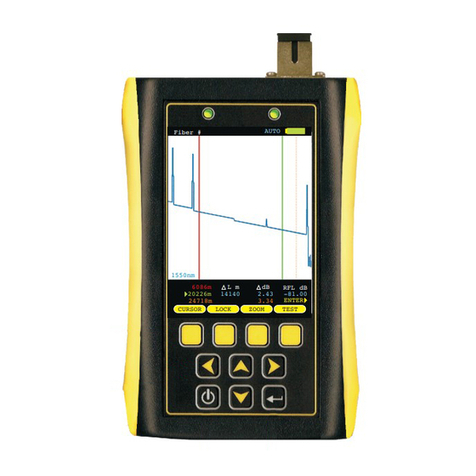
OTDR - optical time domain reflectometer: options include multimode only or singlemode only.
Connector port accepts LC connectors.
OPM - optical power meter; connector port accepts any 2.5mm ferrule connectors (such as SC,
ST, and FC), and 1.25mm ferrule connectors (such as LC).
USB - downloads stored data to a PC using the supplied USB download cable. Also used for
charging the Lithium polymer batteries.
VFL - visual fault locator; Connector port accepts LC connectors.
High-resolution Color LCD Display
- Function keys - activate corresponding menu options shown at the bottom of the Fiber
OWL7+ LCD display
- Arrow keys
- Enter key
- Power key - powers the device on and off; some screens use this key to display context-
sensitive help
GENERAL FEATURES
GENERAL
Display Type
Battery Type
Battery Life
Auto-shutdown
Operating Temperature
Storage Temperature
Dimensions
Weight
2.8” Color LCD
Lithium Polymer
up to 50 hours
Yes
-10 to 55° C
-30 to 70° C
2.87” x 4.42” x 1.25”
10 ounces (284 g)
VFL
VFL Output Wavelength
VFL Output Power
VFL Operating Modes
Connector
VISUAL FAULT LOCATOR
650 nm Laser
1 mW
CW, Modulated
LC
SPECIFICATIONS
OPTICAL POWER METER
Detector Type
Wavelengths
Measurement Range
Accuracy (Uncertainty)
Display Resolution
Measurement Units
Connector Type
Data Storage Points
Download Port Connection
Software
Modes of Operation
InGaAs
850, 980, 1300, 1310, 1490, 1550, 1625 nm
+5 to -70 dBm
±0.15 dB
0.01 dB
dBm, dB
2.5mm / 1.25mm universal
<10,000
USB
OWLView
PAIR, BIDI, CERT, LOSS, OPM
OPTICAL POWER METER (OPM)
1: Using
2: Width measured 1.5dB down on each side of a reflective event using 1 meter pulse width
3: Distance from event beginning to within 0.5dB where backscatter resumes using 1 meter pulse width
4: Out to furthest reflective event
maximum pulse width
Model #:
Fiber Type:
Output Wavelength:
1
Dynamic Range (SNR=1) :
4
Distance Range :
2
Event Dead Zone :
3
Attenuation Dead Zone :
Maximum Data Points:
Data Point Spacing:
Pulse Width:
Index of Refraction:
Distance Accuracy:
Number of Stored Traces:
Model #:
OPTICAL TIME DOMAIN REFELCTOMETER (OTDR)
Singlemode
1550nm
23 dB
x
x
2 meters (typical)
5 meters (typical)
64000
1.4000 to 1.6000
Up to 64km: 1 + (distance in meters/10000) / Over 64km: 2 + (distance in meters/10000)
Maximum trace distance: up to 200 / Minimum trace distance: 3000+
Singlemode
80 miles (128 kilometers)
< 64 km: 1 meter / > 64 km: 2 meters
1, 2, 5, 10, 20, 50, 100, 200, 500, 1k meters
FO7+SFO7+M
Multimode
12 miles (20 kilometers)
1 meter
1, 2, 5, 10, 20, 50, 100 meters
1550 nm
27 dB
1310 nm
28 dB
1300 nm
29 dB
850 nm
27 dB
TEST ZERO UNITS SAVE
CERT
FIBER#1
ACME CORP / HQ WEST
M=COMPUTER ROOM I=NETWORK HUB 3
Length: 12m WAVE:1310nm
EIA/TIA 568C.3 CON: 2
INDOOR SM SPL: 2
-0.24
1310nm
PASS by dB1.86
dB
-0.23
1550nm
PASS by dB1.87
dB
OTDR
CLASS 1M OTDR LASER
CLASS 2 VISIBLE LASER

GENERAL FEATURES
WAVESOURCE PRO SERIES
FIBER OPTIC LIGHT SOURCE
(MODEL #s: WPMX; WPSX; WPMS)
SPECIFICATIONS
Light Source Port (left) - WPMX and WPMS (multimode 850/1300); WPSX (singlemode
1310/1550); port accepts SC connectors
USB - downloads stored data to a PC using the supplied USB download cable. Also used for
charging re-chargeable batteries (not included).
Light Source Port (right) - WPMX (blank); WPSX and WPMS (singlemode 1310/1550); port
accepts SC connectors
Light Source Port Selection LED (left) - lit when the left-hand port is active
Power/Battery Charter LED - lit when unit is powered on
Battery/charging status
battery fully charged
battery charging
problem with battery and/or charger
Light Source Port Selection LED (right) - lit when the right-hand port is active
Wavelength Display LED - displays current output wavelength when lit; LED turns off after 3
seconds; press to show wavelength
- CW / MOD button
Press: toggle source between CW (continuous wave) and MOD (modulated) mode.
- Power button
Hold: power ON and OFF
Press: display wavelength
- 8/AUTO button
Press: toggle between wavelengths in the selected port
Hold: set AUTO mode; source alternates wavelengths within the active port for
automatic dual-wavelength testing
- PORT button
Press: toggle between light source ports
GREEN
ORANGE
RED
GENERAL
Display Type
Battery Type
Battery Life
Auto-shutdown
Operating Temperature
Storage Temperature
Dimensions
Weight
2.8” Color LCD
Lithium Polymer
up to 50 hours
Yes
-10 to 55° C
-30 to 70° C
2.87” x 4.42” x 1.25”
10 ounces (284 g)
Model #:
Source Type:
Calibrated Wavelengths
Output Power (CW)
Accuracy
Light Source Drift (1hr.)
Spectral Width (FWHM)
Modulation Frequencies
Fiber Type:
FIBER OPTIC LIGHT SOURCE
Laser
-10 dBm
±0.10 dB @ 25°C
Singlemode
LED
-20 dBm
±0.10 dB @ 25°C
Multimode
1550 nm
±0.04 dB
3nm
1310 nm
±0.05 dB
2nm
1300 nm
±0.05 dB
180nm
850 nm
±0.05 dB
50nm
M
300 Hz / 600 Hz / 1 kHz / 2 kHz
Optical Source
WaveSource Pro
1 3 1 0. . .

INTRODUCTION
Fiber OWL7+ certification test kits include a Tier 2 certification meter and light source that enable fiber optic professionals to perform a
wide range of tests, from basic optical power/loss measurement all the way up to full-featured Tier 2 certification (PASS/FAIL and
OTDR trace results) for their clients.
Models are available that can test multimode only, singlemode only, or both multimode and singlemode. Optional accessories such
as OTDR fiber rings and video inspection microscopes are also available to take full advantage of Tier 2 certification capability.
Fiber OWL 7+ certification power meter. Test readings and graphical help screens can be easily viewed on the color LCD, and an
intuitive 10-key keypad allows for easy data entry.
The intuitive built-in Link Wizard prompts the user to enter key information used to calculate standards-based link budgets for fiber
optic certification testing, and helpful diagrams guide the user through the setup and testing procedure.
Thousands of data points tored information can be
selectively viewed, re-tested, or deleted from the device.
WaveSource Pro fiber optic light source. An intuitive 4-button keypad controls key functions such as port and wavelength
selection, and a 7-segment LED displays the currently selected wavelength.
Both the meter and source are enclosed in attractive hand-held cases made from high impact plastic and protected by a protective
rubber boot, and are powered by re-chargeable lithium polymer batteries which are re-charged through a USB port via a supplied
battery charger and cable.
Following is a short description for each of the functions that can be performed with these devices, which will be covered in more detail
later in this manual.
with descriptive link and fiber run labels can be stored in internal memory. S
DESCRIPTION
APPLICATIONS
Transmitter Power Measurement (OPM MODE). The Fiber OWL 7+ meter can be used as a basic power meter (OPM) to measure
the output power of active equipment transmitters, which is useful for two different purposes:
The output power of the transmitter can be measured by connecting the meter directly to the transmitter port; and
The transmitter power can also be measured through the link, which is helpful for determining if the received power of the
equipment at the far end is within the equipment’s receiver sensitivity range.
OPTICAL POWER
MEASUREMENT
Measure
receiver
sensitivity
Measure
transmitter
power
TEST SAVE
OPM
FIBER#1
ACME CORP / HQ WEST
M=COMPUTER ROOM I=NETWORK HUB 3
Length:xxx100m WAVE: 1310
EIA/TIA 568C.3 CON:X2
INDOOR SM SPL:X2 ENTER
-10.24
1310n m
PASS by 1.8 6dB
dBm
TEST SAVE
OPM
FIBER#1
ACME CORP / HQ WEST
M=COMPUTER ROOM I=NETWORK HUB 3
Length:xxx100m WAVE: 1310
EIA/TIA 568C.3 CON:X2
INDOOR SM SPL:X2 ENTER
-10.24
1310n m
PASS by 1.8 6dB
dBm

INTRODUCTION
APPLICATIONS, cont.
Checking patch cables (OPM MODE). As an optical power meter (OPM), the Fiber OWL 7+ is also useful for performing a quick
check of patch cables, to ensure that the patch cables are okay to use for testing (when connected to the output of the NIST calibrated
light source).
And, assuming the patch cable is good, users can periodically monitor the NIST calibration levels of the light source outputs and
power meter detector to make sure they are within the device specifications.
OTDR Measurement. Using the OTDR in Fiber OWL 7+ fiber certifiers, users can acquire a trace of events for the purpose of
characterizing the network or troubleshooting for problems, as well as determine the end to end length of the fiber link.
Visual Fault Location. The Fiber OWL 7+ contains a visual fault locator port used for quick troubleshooting of optical faults close to
the near-end of the optical fiber under test, or for visually identifying fibers (up to 5km in typical fiber links).
The 2.5mm universal VFLport is located on the left-hand side on the top of the OTDR.
OTDR
– Characterize the network (i.e. get a “road-map” of the fiber)
– Troubleshoot for problems such as breaks or other types of optical faults
– Measure end-to-end length
06086m
20226m
24718m
RFL dBx
-81.00x
14140
dB
2.43x
3.34x
L mx
Fiber #x
TESTMENULOCKCURSOR
ENTER
1550nm
AUTO H
VISUAL
FAULT
LOCATOR
– Quickly troubleshoot faults in the near-end of the fiber under test
– Identify fibers visually (typically up to 5 km)
06086m
20226m
24718m
RFL dBx
-81.00x
14140
dB
2.43x
3.34x
L mx
Fiber #x
TESTMENULOCKCURSOR
ENTER
1550nm
AUTO H
CHECK
PATCH
CABLES
TEST SAVE
OPM
FIBER#1
ACME CORP / HQ WEST
M=COMPUTER ROOM I=NETWORK HUB 3
Length:xxx100m WAVE: 1310
EIA/TIA 568C.3 CON:X2
INDOOR SM SPL:X2 ENTER
-10.24
1310n m
PASS by 1.8 6dB
dBm
Optical Source
WaveSource Pro
AUTO
PORT
MOD
CW

INTRODUCTION
APPLICATIONS, cont.
Attenuation (Optical Loss) Measurements (LOSS MODE). After a fiber cable has been installed and terminated, optical loss
measurements can be used to determine if the fiber is installed according to standards and specifications. Acomparison between the
actual power measurement and the reference value determines how much optical power is lost through the link.
Fiber Optic Link Certification (CERT MODE). Certify individual optical fibers at up to two wavelengths simultaneously. The Link
Wizard in the Fiber OWL 7+ uses attenuation parameters from popular cabling standards to certify fiber links, and shows a link’s
PASS/FAILstatus right in the field.
TIER 2 Certification (FULL MODE). Tier 2 certification is defined in the TIA-568 cabling standard as a way to give end users a more
comprehensive set of test results. Tier 2 certification combines traditional certification test results (i.e. Tier 1) with OTDR test results.
The Fiber OWL 7+ includes a test mode called FULL mode that guides the user through the Tier 2 certification process – first, all fibers
are tested with the OTDR, then certification results are added once all the OTDR traces have been taken.
OWLView software enables users to download FULL MODE test results into one convenient project file, and both sets of results
conveniently appear on printed test reports and PDFs.
OPTICAL
LOSS
MEASUREMENT
Using a meter and a source, technicians can
measure the optical loss of optical fiber links.
Optical Source
WaveSource Pro
AUTO
PORT
MOD
CW
TEST SAVE
LOSS
FIBER#1
ACME CORP / HQ WEST
M=COMPUTER ROOM I=NETWORK HUB 3
Length: 100m WAVE:
EIA/TIA 568C.3 CON: 2
INDOOR SM SPL: 2
xxx
X
X
1310
ENTER
-0.24
1310n m REL
Ref: -10.48dBm
dB
-0.23
1550n m REL
Ref: -10.52dBm
dB
FIBER OPTIC
LINK CERTIFICATION
(aka TIER 1 certification)
Using a meter and a source,
each individual fiber is certified separately.
Optical Source
WaveSource Pro
AUTO
PORT
MOD
CW
TEST SAVE
CERT
FIBER#1
ACME CORP / HQ WEST
M=COMPUTER ROOM I=NETWORK HUB 3
Length: 100m WAVE:
EIA/TIA 568C.3 CON: 2
INDOOR SM SPL: 2
xxx
X
X
1310
ENTER
-0.24
1310n m
PASS 1.86by dB
dB
-0.23
1550n m
PASS 1.86by dB
dB

INTRODUCTION
PRECAUTIONS
Safety - Exercise caution when working with any optical equipment. High-intensity fiber optic laser sources output potentially
dangerous high energy invisible light, and could cause serious, irreparable damage to the eye. Thus, it is recommended to
look into the connector port of a light source or the end of a fiber.
Operational - It is important to keep connector ferrules and optical connector ports clean. If dirt, dust, and oil are allowed to build up
inside connector ports, irreparable damage may occur to the optics inside the port. For best results, replace dust caps after each use.
Light Source Connector - Do NOT insert APC (Angled Physical Contact) connectors into any light source or OTDR port on your
Fiber OWL7+ or WaveSource Pro as this may damage the angled ferrule on theAPC connector.
NEVER
On the back of each unit included with Fiber OWL 7+ series fiber link certifiers are labels similar to the one shown below containing
model number, serial number, power requirements, and special cautionary information.
PRODUCT LABEL
WARNING
MADE IN USA
MODEL#: F7MX
SERIAL#: F7MX99999
POWER: 6V DC, 1A
This product complies with the
following EU Directives:
EN 61326-1:2006
EN 61010-1:2001
Singlemode
1310nm: 0.1 mW
FP Laser
IEC 60825-1

INTRODUCTION
WHAT DO YOU WANT TO DO?
Below is a list of the available operations in the Fiber OWL7+, and the test mode to use for those operations:
Operation Section
Measure the output of active equipment transmitters OPM MODE
Measure the output power at active equipment receiver OPM MODE
Check patch cables OPM MODE
Verify NIST calibration levels OPM MODE
Basic optical loss measurement without storing test results OPM MODE
Measure length of fiber cables OTDR MODE
Characterize the network OTDR MODE
Troubleshoot problems in the fiber OTDR MODE
Basic optical loss measurement and store test results LOSS MODE
Certify fiber links only (Tier 1 testing only; no OTDR results) CERTMODE
OTDR testing only OTDR MODE
Tier 2 testing –Tier 1 certification + OTDR results FULLMODE
Visual fault location VFL
Visual fiber identification VFL

OPM MODE
OVERVIEW
TEST PROCEDURES
OPM MODE
Optical power is an absolute measurement of the amount of light intensity; i.e. “brightness”, and is one of the
most basic tests performed by an optical power meter (OPM). The Fiber OWL 7+ contains a basic OPM MODE
for this purpose.
APPLICATIONS
OPM MODE enables users to perform the following basic tests:
Transmitter power measurement
Receiver sensitivity measurement
Checking patch cables
Verification of NIST calibration levels
Basic optical loss measurement
OPM MODE is indicated at the top of the display.
Since OPM MODE is designed for basic power and loss
measurements only, data storage functions are not
available.
FUNCTION KEY OPTIONS
Several OPM-related functions are available via the yellow function
button menu located at the bottom of the display.
toggle between menu lists
change currently selected wavelength (when source is NOT set toAUTO)
set an optical reference
change measurement units between dBm (ABS) and dB (REL)
resume testing for a previously stored project
switch to SIMPLE OTDR mode (see OTDR section)
return to STARTUP MENU
WAVE
ZERO
UNITS
LOAD
OTDR
MENU
TEST ZERO WAVE SAVE
OPM
FIBER#1
ACME CORP / HQ WEST
M=COMPUTER ROOM I=NETWORK HUB 3
Length: 12m
EIA/TIA 568C.3 CON: 2
INDOOR SM SPL: 2
WAVE:1310nm
-10.24
1310nm ABS
Ref: -10.24dBm
dBm
-10.23
1550nm ABS
Ref: -10.23dBm
dBm

ACCESSING OPM MODE
TEST PROCEDURES
Power on the Fiber OWL 7+.
Or, if meter is already powered on, press
MENU.
Press to POWER METER, then to
continue.
The meter will immediately begin to display optical power (dBm; ABS) or loss (dB; REL) readings.
OPM MODE
LEN WAVE SAVE
OPM
FIBER#1
ACME CORP / HQ WEST
M=COMPUTER ROOM I=NETWORK HUB 3
Length:xxx100m
EIA/TIA 568C.3 CON:X2
INDOOR SM SPL:X2
WAVE:
1310
ENTER
LOW
1310nm ABS
PASS by 1.86dB
dBm
LOW
1550nm
PASS by 1.87dB
dBm
AVAILABLE FUNCTIONS
Select next wavelength
Set optical reference
Toggle display units between dBm (optical power) and dB (optical loss)
Load a previously stored link (make sure that references are re-set before taking further
measurement)
Switch to SIMPLE OTDR mode (see OTDR section)
Return to STARTUP MENU
DISPLAYED RESULT
LOW No measurable amount of incoming optical power
HIGH Incoming optical power is too bright to be measured
(black) Normal optical power/loss measurement
(blue) INVALID OPERATING MARGIN (indicates invalid
“negative loss” or “gain” test condition;
recommended to re-set the reference using the ZERO
function)
WAVE
ZERO
UNITS
LOAD
OTDR
MENU
Possible causes for “LOW”:
– Test cable not connected to OPM port
– Light source not powered on
– Light source set to incorrect port
– Too much link loss
– Transmitter power too low
– No continuity
STARTUP MENU
CERTIFICATION MENU
POWER METER
SIMPLE OTDR
SETUP MENU
HELP TOPICS
SELECT EXIT
BACK
Optical power meter without
storage mode

TRANSMITTER OUTPUT POWER MEASUREMENT
TEST PROCEDURES
Connect the Fiber OWL 7+ to the transmitter (TX)
port of the transmission equipment (e.g. switch,
router, hub, GBIC, light source, etc.) and make
sure the equipment is powered on.
example: network switch
Press WAVE until the meter is set to the same
wavelength as the network equipment.
Press UNITS until the meter is set to display
optical power in dBm.
example: network switch
View the displayed optical power.
NOTE: if the transmitter is sending out digital data, the displayed power
level will fluctuate based on average power of data bits received during
the sampling period.
example: network switch
Measure the output power directly from network transmission equipment to determine if the equipment is
transmitting within manufacturer output power specifications.
OPM MODE
LEN WAVE SAVE
OPM
FIBER#1
ACME CORP / HQ WEST
M=COMPUTER ROOM I=NETWORK HUB 3
Length:xxx100m
EIA/TIA 568C.3 CON:X2
INDOOR SM SPL:X2
WAVE:
1310
ENTER
-4.72
1310nm ABS
PASS by 1.86dB
dBm
LOW
1550nm
PASS by 1.87dB
dBm
LEN WAVE SAVE
OPM
FIBER#1
ACME CORP / HQ WEST
M=COMPUTER ROOM I=NETWORK HUB 3
Length:xxx100m
EIA/TIA 568C.3 CON:X2
INDOOR SM SPL:X2
WAVE:
1310
ENTER
LOW
1310nm ABS
PASS by 1.86dB
dBm
LOW
1550nm
PASS by 1.87dB
dBm
LEN WAVE SAVE
OPM
FIBER#1
ACME CORP / HQ WEST
M=COMPUTER ROOM I=NETWORK HUB 3
Length:xxx100m
EIA/TIA 568C.3 CON:X2
INDOOR SM SPL:X2
WAVE:
1310
ENTER
LOW
1310nm ABS
PASS by 1.86dB
dBm
LOW
1550nm
PASS by 1.87dB
dBm

TEST PROCEDURES
RECEIVER SENSITIVITY MEASUREMENT
Output power measured from a transmitter through a link at the far-end receiver will determine if the
received power is within manufacturer receiver sensitivity specifications.
OPM MODE
Remove the patch cable from the
receiver (RX) port.
TX RX TX RX
Connect the patch cable to the OPM port on the
Fiber OWL 7+. Set the meter to dBm mode, and
also the same wavelength as the transmitter.
TX RX TX RX
LEN WAVE SAVE
OPM
FIBER#1
ACME CORP / HQ WEST
M=COMPUTER ROOM I=NETWORK HUB 3
Length:xxx100m
EIA/TIA 568C.3 CON:X2
INDOOR SM SPL:X2
WAVE:
1310
ENTER
LOW
1310nm ABS
PASS by 1.86dB
dBm
LOW
1550nm
PASS by 1.87dB
dBm
View displayed receiver sensitivity power level.
NOTE: if the transmitter is sending out digital data, the displayed power
level will fluctuate based on average power of data bits received during
the sampling period.
TX RX TX RX
LEN WAVE SAVE
OPM
FIBER#1
ACME CORP / HQ WEST
M=COMPUTER ROOM I=NETWORK HUB 3
Length:xxx100m
EIA/TIA 568C.3 CON:X2
INDOOR SM SPL:X2
WAVE:
1310
ENTER
-14.72
1310nm ABS
PASS by 1.86dB
dBm
LOW
1550nm
PASS by 1.87dB
dBm

TEST PROCEDURES
PATCH CABLE VERIFICATION
OPM MODE
Check patch cables before testing to determine if they are okay to use.
If patch cable measurements are within specifications, the user has verified that: 1) the patch cable is good;
and 2) the units are measuring within their calibration levels.
Connect the patch cable to be tested between the OPM port on the Fiber OWL 7+, and the appropriate
source port on the WaveSource Pro.
Hold – set the WaveSource Pro to AUTO mode
– set measurement units to dBm
Both available wavelengths should appear on
the Fiber OWL 7+ display.
Light source calibration levels ( ):
Singlemode: -10.00 dBm
62.5/125 multimode: -20.00 dBm
50/125 multimode: -23.00 dBm
actual measurements values may be slightly above or below
light source calibration levels, but should be close
AUTO
UNITS
Optical Source
WaveSource Pro
AUTO
PORT
MOD
CW
LEN WAVE SAVE
OPM
FIBER#1
ACME CORP / HQ WEST
M=COMPUTER ROOM I=NETWORK HUB 3
Length:xxx100m
EIA/TIA 568C.3 CON:X2
INDOOR SM SPL:X2
WAVE:
1310
ENTER
-10.00
1310nm ABS
PASS by 1.86dB
dBm
-10.00
1550nm ABS
PASS by 1.87dB
dBm

TEST PROCEDURES
OPTICAL LOSS MEASUREMENT
Measure the attenuation, or loss, of optical fiber links.
OPM MODE
Power ON the Fiber OWL 7+.
Optical Source
WaveSource Pro
AUTO
PORT
MOD
CW
STARTUP MENU
CERTIFICATION MENU
POWER METER
SIMPLE OTDR
SETUP MENU
HELP TOPICS
SELECT EXIT
BACK
Optical power meter without
storage mode
– Power ON the
Fiber OWL 7+
– Select
POWER METER
option from the
STARTUP MENU
Start the Set Optical Reference procedure.
Optical Source
WaveSource Pro
AUTO
PORT
MOD
CW
– toggle function
menu
– begin set
reference procedure
ZERO
OPM
FIBER#1
ACME CORP / HQ WEST
M=COMPUTER ROOM I=NETWORK HUB 3
Length:xxx100m
EIA/TIA 568C.3 CON:X2
INDOOR SM SPL:X2
WAVE:
850nm
ENTER
LOW
1850nm REL
Ref: -10.17dBm
dB
-10.28
1550nm ABS
Ref: -10.28dBm
dBm
LEN WAVE SAVE
ZERO UNITS LOAD

TEST PROCEDURES
OPTICAL LOSS MEASUREMENT, cont.
OPM MODE
Connect the appropriate reference cables between the Fiber OWL 7+ and WaveSource Pro.
Press any key to
proceed.
Optical Source
WaveSource Pro
AUTO
PORT
MOD
CW
Using your test reference
cables, please connect the meter
and source as shown and
press any key to proceed.
Review the “Setting a reference” screen.
– continue
YES
Optical Source
WaveSource Pro
AUTO
PORT
MOD
CW
Setting a reference
(aka “zeroing”)
Sets a baseline optical power
level between a power meter
and light source prior to
taking measurements.
The difference between this
reference level and the
link power measurement
is called optical loss.
You must set a zero reference
before testing. Do you wish
to do it now?
YES NO
Table of contents
Other OWL Measuring Instrument manuals
OWL
OWL OWLTrek WTO-S15 User manual

OWL
OWL OWLTrek WTO-M85 User manual

OWL
OWL F7BMS MM User manual

OWL
OWL Micro OWL 2 Series User manual

OWL
OWL ZOOM 2 Series Manual

OWL
OWL CM119 User manual

OWL
OWL KIT-FO4B-WSMDst User manual

OWL
OWL WaveTester Series User manual

OWL
OWL KIT-Z2-L2 Series User manual

OWL
OWL WT-1 User manual

OWL
OWL OWL+USB Installation guide

OWL
OWL VOLT-1 User manual

OWL
OWL Laser Hoots User manual

OWL
OWL FO-4V User manual
OWL
OWL ZOOM 2 Series User manual

OWL
OWL 4 BOLT Series User manual

OWL
OWL OWLTrek II WTO2-S13 User manual

OWL
OWL WaveSource Series User manual

OWL
OWL MPO Series User manual
OWL
OWL ZOOM 2 ZO2 User manual