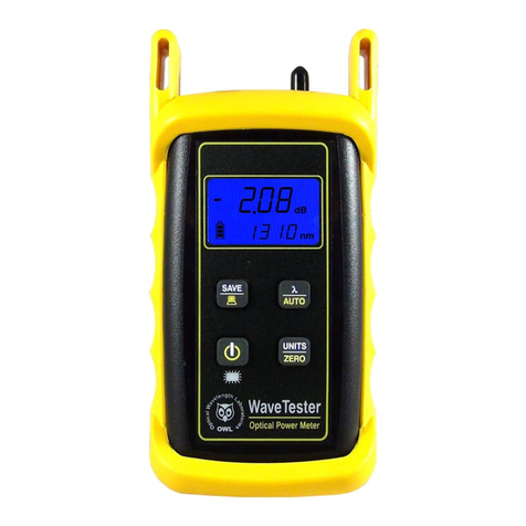
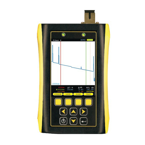
OWL WT-1 User manual

OWL-INC.COM
Revision 2.0
April 18, 2019 Optical Wavelength Laboratories (OWL)
N9623 West US Hwy 12
Whitewater, WI 53190
Phone: 262-473-0643
Internet: OWL-INC.COM
Optical Wavelength Laboratories
OPERATIONS GUIDE
WAVETESTER OPTICAL POWER METER
Model Numbers:
WT-1
WT-1V

i
INTRODUCTION
TABLE OF CONTENTS
Introduction
Before You Begin 1
About This Manual 1
Applications 2
Description 2
Precautions 3
Product Label 3
General Features 4
Test Procedures
Active Equipment Power Measurement 5
Fiber Continuity 6
Patch Cable Testing 7
Check MM Reference Cables - Dual OWL MM Sources 8
Check MM Reference Cables - WaveSource MM Sources 9
Check SM Reference Cables - Laser OWL SM Sources 10
Check SM Reference Cables - WaveSource SM Sources 11
Quick Reference Guides
WaveTester/Dual OWL MM Test Kits 12
WaveTester/WaveSource MM Test Kits 17
WaveTester/Laser OWL SM Test Kits 21
WaveTester/WaveSource SM Test Kits 24
OWL Reporter
Installing OWL Reporter 27
Installing the OWL USB Driver 29
Downloading Data to a PC 31
Interpreting OWL Reporter Screens and Reports 38
Operation/Maintenance
WaveTester Data Storage Error Codes 44
Clearing Data from WaveTester Memory 44
PC-Based Meter Control 45
Optional VFL Port 46
Visual Fault Location 47
Visual Fiber Identification 48
Universal Port 49
Use of SC Connectors with 2.5mm Universal Port 49
Cleaning the Detector Port 50
Cleaning the Optional VFL Port 51
Appendices
Specifications 52
Maintenance and Calibration Information 52
Contact Information 52
Optional Upgrade Information 52
Supported Cabling Standards 53
10-Gigabit Ethernet Standard 53
Link Budget Calculation Worksheet

1
INTRODUCTION
BEFORE YOU BEGIN
All personnel testing optical fibers should be adequately trained in the field of fiber optics before using any fiber optic test
equipment.
If the user is not completely familiar with testing fiber optics, they should seek competent training. Such training can be acquired
from a variety of sources, such as local hands-on training classes.
Valuable information about fiber optic testing can also be gathered from reading printed literature carefully or by thoroughly
reading supplied operations manuals.
Fiber optic testers vary from other types of test equipment due to issues such as:
1) standards-based testing
2) proper fiber optic test procedures (FOTPs)
3) "zeroing" or referencing of power levels
4) determining the correct link budget to pass or fail by
Complete understanding of each of these issues is critical for performing proper fiber optic tests.
Throughout this manual you will find various symbols that assist with understanding the procedures outlined in this manual.
Below is a list of these symbols and a short description of their purpose:
Shows a helpful tip that will make a procedure go more smoothly
Tells the user some useful information about the successful completion of a procedure
Warns the operator of a potentially dangerous condition
ABOUT THIS MANUAL

2
INTRODUCTION
APPLICATIONS
Below is a list of test and measurement applications that can be performed using the WaveTester optical power meter. The
procedure for each one of these applications is covered in detail in this manual.
Active Equipment Optical Power Measurements. Active equipment should be measured periodically for correct power levels.
The transmitters in this equipment have a known power value. The WaveTester can be directly attached to this equipment via a
patch cord to check whether the transmitter is within the manufacturer’s specified power range.
Fiber Continuity Testing. Continuity can be measured with the WaveTester by placing a calibrated light source on one end of
the fiber and the WaveTester on the other end. This is also a simple way to measure the attenuation of the fiber.
Patch Cord Testing. Fiber links that are producing incorrect results may have bad patch cords. The WaveTester can be used to
test the attenuation of a patch cord to see if it is usable, or should be replaced.
Attenuation (Optical Loss) Measurements. After a fiber cable has been installed and terminated, it must be tested to
determine if the fiber is installed according to standards and specifications. A comparison of the actual power measurement and
the reference value determines if the installation will pass or fail. Up to 200 fiber measurements may be stored for later download
into OWL Reporter software.
This manual describes the operation of the WaveTester optical power meter. The WaveTester is a very economical option for
measuring the optical power of both multimode and singlemode fibers. The WaveTester is NIST traceable, and is calibrated 850,
1300, 1310, and 1550nm, as well as 1490nm, one of the key wavelengths used in FTTx PON networks. Reference values used
for optical loss readings are stored for each of these wavelengths.
The WaveTester has a user-friendly interface which includes four push-buttons, and also includes a 2.5mm universal connector,
which is compatible with many popular fiber connectors, such as ST, SC, and FC, and a 1.25mm universal connector adapter that
allows for connection to LC, MU, and other SFF connectors.
The WaveTester is ideal for fiber optic professionals who need to quickly measure the loss in their fiber optic links, as well as
simple data storage and auto-testing fiber link certification.
For an additional charge, the WaveTester can include a precision-coupled visual fault locator optimized for fiber optics. An
optical ball lens placed near the laser output focuses the light for optimum input into fiber optic cables, and special current-limiting
electronics prevents laser burnout (a common problem with pen-style laser pointers), increasing the life of the VFL.
DESCRIPTION

3
INTRODUCTION
PRECAUTIONS
Safety - Exercise caution when working with any optical equipment. High-intensity fiber optic laser sources output potentially
dangerous high energy invisible light, and could cause serious, irreparable damage to the eye. Thus, it is recommended to
look into the connector port of a light source or the end of a fiber.
Operational - It is important to keep connector ferrules and optical connector ports clean. If dirt, dust, and oil are allowed to build
up inside connector ports, irreparable damage may occur to the optics inside the port. For best results, replace dust caps after
each use.
Connector - if you have the optional Visual Fault Locator installed, do NOT insert APC (Angled Physical Contact) connectors into
the VFL port on your WaveTester as this may damage the angled ferrule on the APC connector.
NEVER
On the back of each WaveTester series optical power meter is a label similar to the one shown below containing model number,
serial number, power requirements, and special cautionary information. If the unit is enclosed in its protective boot, the boot must
be removed to view this label.
PRODUCT LABEL
Optical Wavelength Laboratories
Whitewater, WI 53190 (262) 473-0643
MODEL# WT-1
SERIAL# WT11019
POWER: 5V DC
MADE IN USA
Conforms to the Harmonized European
Standards EN 61326-1 and EN 61010-1.
Visible Optical Radiation When
VFL Is Set To The ON
Position -- Avoid Eye
Exposure To Direct Radiation
IEC 60825-1
Red Laser: 650 nm ~ 0 dBm
CAUTION: If optional VFL is installed:
Optical Wavelength Laboratories
Whitewater, WI 53190 (262) 473-0643
MODEL# WT-1V
SERIAL# WT81019
POWER: 9V DC
MADE IN USA
Conforms to the Harmonized European
Standards EN 61326-1 and EN 61010-1.
Visible Optical Radiation When
VFL Is Set To The ON
Position -- Avoid Eye
Exposure To Direct Radiation
IEC 60825-1
Red Laser: 650 nm ~ 0 dBm
CAUTION: If optional VFL is installed:

GENERAL FEATURES
4
INTRODUCTION
Optional VFL Port -
installed in this port.
USB Download/Battery Charger Port - downloads stored data to a PC, or
charges the internal battery, using the supplied USB download cable.
Universal Detector Port - 2.5mm adapter cap accepts 2.5mm ferrule
connectors, including ST, SC, and FC; 1.25mm universal adapter cap
accepts 1.25mm ferrule connectors (LC, MU, and other SFF connectors).
LCD Display - shows optical power/loss levels, power units, wavelength,
and battery status.
As an option, a Visual Fault Locator (VFL) can be
- PRESS: saves the current measurements; HOLD: download data to
terminal program such as Hyperterminal.
- While powered off: PRESS: power on.
While powered on:
PRESS: backlight on/off; if optional VFLis installed, also:
PRESS: VFL on continuous (backlight turns off);
PRESS: VFL flashes;
PRESS: VFL OFF
HOLD: power off
- PRESS: changes the measurement wavelength; HOLD: enable
AUTO mode (for auto-wavelength switching when used with an OWL
WaveSource series light source).
- PRESS: toggle measurement units between dBm, dB, and :W;
HOLD: set optical reference (also known as “zeroing”; if AUTO mode is
enabled, sets reference for both available wavelengths).
SAVE
AUTO
UNITS
ZERO
3
2
4
5
6
7
8
DETECTOR
USB
13
2
Model #:
WT-1V
Model #:
WT-1
dBm
. . .20.00
-
850
nm
4
57
68

Required Accessories
(1 or 2) one-meter patch cable(s) – (ensure proper connector type and fiber type)
Direct Transmitter Output Power Measurement
To measure the output power from a transmitter, use the following steps:
Connect the WaveTester to the transmitter port on the active equipment
under test, as shown at right.
Press to power on the WaveTester optical power meter, if necessary.
Determine the output wavelength of the active equipment, then press
until the wavelength on the WaveTester matches.
Power on the transmitter port according to manufacturer instructions, if
necessary.
Monitor the reading on the screen for a few seconds. This reading may fluctuate if the output signal is made up of digital
zeroes (0) and ones (1). In this case, estimate the average power level. To calculate maximum output power, add 3 dB
to the average power level.
Some transmitters have a diagnostic mode where the output is continuously at its maximum power. This
eliminates the need to compensate 3dB for digital data transmission. Consult the active equipment
manufacturer’s operations guide for more information.
Receive Power Measurement
The WaveTester may also be used to measure optical power levels from a
transmitter through an installed link to ensure that the Receive power at the far
end is within manufacturer specifications.
Follow the same steps as above, except the WaveTester must be connected to
the active equipment under test through the installed link as shown at right.
AUTO
5
TEST PROCEDURES
ACTIVE EQUIPMENT POWER MEASUREMENT
Active Equipment
Transmitter Power
Measurement
Receive Power
Measurement
12345678910 11 12 12345678910 11 12

Required Accessories
(2) one-meter patch cables – (ensure proper connector type and fiber type)
Checking for Fiber Continuity
The WaveTester can be used to verify continuity of a fiber link, or can be used to
trace an optical fiber if the fibers are not properly labeled. Use the following
procedure to test either multimode and singlemode cables.
Connect a fiber optic light source to the network port under test as shown
at right. Power on the light source according to manufacturer
instructions.
Press to power on the WaveTester optical power meter, if
necessary.
Press until the wavelength on the WaveTester matches the output
wavelength of the light source.
Take the WaveTester optical power meter to the opposite end of the link under test, and connect into the first port. If the
WaveTester does not detect any optical power, the display will read “LO”. Continue connecting to subsequent optical
ports until the WaveTester display shows an optical power reading.
If none of the ports display an optical power reading, then it is likely that there is a major connectivity problem with the link,
and further troubleshooting is necessary to determine the nature of the problem.
AUTO
6
TEST PROCEDURES
FIBER CONTINUITY
MEASUREMENT
12345678910 11 12 12345678910 11 12
FIBER CONTINUITY

Required Accessories
(3) one-meter patch cables – (ensure proper connector type and fiber type)
(2) fiber optic adapters/couplers – (ensure proper connector type)
Patch Cable Insertion Loss
Patch cables should be tested periodically to ensure that they are okay to use for
testing. Use the following procedure to test both multimode and singlemode
patch cables.
If testing at more than one wavelength, this procedure must
be performed for each wavelength separately.
Connect the WaveTester to a fiber optic light source using the 3-jumper
reference method as shown at right. Power on the light source according
to manufacturer instructions.
Press to power on the WaveTester optical power meter, if necessary.
Press until the wavelength on the WaveTester matches the output
wavelength of the light source.
Press and hold for approximately 2 seconds to set the reference.
The WaveTester will change to show loss in ‘dB’, and the loss value
should be very close to 0.00 dB.
Setting a reference is commonly referred to as “zeroing”.
Remove the center cable as shown at right.
Insert a patch cable under test between the two fiber optic
adapters/couplers, then record the loss value in ‘dB’.
Repeat steps and for each patch cable being tested.
AUTO
UNITS
ZERO
7
TEST PROCEDURES
3-jumper Reference
Method Setup
PATCH CABLE TESTING
Insertion Loss Test

8
TEST PROCEDURES
LIGHT SOURCE MODEL NUMBERS:
DO2xx
DO2-85xx
DO2-13xx
Checking Series Optical Power Meters
For Proper Operation
USING OWL DUAL OWL SERIES MULTIMODE SOURCES
WaveTester
Checking WaveTester Series Optical Power
Meters for Proper Operation
USING A DUAL OWL MULTIMODE LIGHT SOURCE
STEP 1 - Connect WaveTester and Dual OWL
Connect the WaveTester and Dual OWL together with an orange
multimode patch cable as shown below.
STEP 2 - Power ON the WaveTester
Press to power on the
WaveTester.
After a few seconds, the
WaveTester display should read
‘LO’, and will appear similar to
the diagram shown at right.
NOTE: the wavelength and measurement units may be different
from the display at right.
STEP 3 - Set the WaveTester to ‘dBm’
Press on the WaveTester
until the measurement units
read ‘dBm’ as shown at right.
You may need to press the
button several times.
NOTE: it is recommended to thoroughly clean and inspect all
patch cord connectors before making any connection.
OF F
ON
U NIT S
Z E R O
dBm
.8. . .8lo
-
i850
nm
dBm
.8. . .8lo
-
i850
nm
STEP 4 - Set WaveTester to 850nm
Press on the WaveTester
until the wavelength display
shows ‘850nm’ as shown at
right. You may need to press
the button several times.
STEP 5 - Power ON the Dual OWL
Press to power on the
Dual OWL.
The 850nm indicator LED
should now be lit as shown at
right.
STEP 6 - Check optical power
The power reading that appears
on the WaveTester display will
depend upon cable type.
Consult the table below for a list
of acceptable power readings.
STEP 7 - Replace the patch cable
The easiest way to troubleshoot low power levels is to try another
patch cable. Over time, patch cables can wear out or become
damaged the more they are used for optical loss testing.
Replacing the patch cable usually fixes the problem.
STEP 8 - Clean patch cables and optical ports
If the problem still exists after patch cable replacement, there
may be some debris, such as dust, dirt, or finger oil, that has
collected on the connector endface or in the equipment optical
ports.
Thoroughly clean and inspect the optical ports of the
WaveTester and the Dual OWL, as well as the fiber connector
endfaces, according to the brochures that have been included
with this kit. Several cleaning cycles may be required.
If the power level is still too low, even after a thorough cleaning
and inspection and patch cable replacement, contact OWL
technical support at 262-473-0643 for more information.
NOTE: the following steps are only required if the optical power
reading on the WaveTester is too low.
AU T O
dBm
.8. . .8lo
-
850
nm
dBm
.20.00
-
850
nm
Core Size
62.5/125 µM
50/125 µM
Replace at
-21.00 dBm
-24.00 dBm
Acceptable Power Level
-19.0 to -21.0 dBm
-22.0 to -24.0 dBm
DUAL OWL
connected to
850nm port
SC connectors shown here;
connector style may vary
LIGHT SOURCE
CONNECTOR PORTS
Do NOT insert APC connector
into either light source port

9
TEST PROCEDURES
LIGHT SOURCE MODEL NUMBERS:
WS-MDxx
WS-MDVxx
WS-MDSDxx
Checking Series Optical Power Meters
For Proper Operation
USING OWL WAVESOURCE SERIES MULTIMODE SOURCES
WaveTester
STEP 4 - Set WaveTester to 850nm
Press on the WaveTester
until the wavelength display
shows ‘850nm’ as shown at
right. You may need to press
the button several times.
STEP 5 - Power ON the WaveSource
Press to power on the
WaveSource.
The 850nm indicator LED
should now be lit as shown at
right.
STEP 6 - Check optical
power
The power reading that appears
on the WaveTester display will
depend upon cable type.
Consult the table below for a list
of acceptable power readings.
STEP 7 - Replace the patch cable
The easiest way to troubleshoot low power levels is to try another
patch cable. Over time, patch cables can wear out or become
damaged the more they are used for optical loss testing.
Replacing the patch cable usually fixes the problem.
STEP 8 - Clean patch cables and optical ports
If the problem still exists after patch cable replacement, there
may be some debris, such as dust, dirt, or finger oil, that has
collected on the connector endface or in the equipment optical
ports.
Thoroughly clean and inspect the optical ports of the
WaveTester and the WaveSource, as well as the fiber connector
endfaces, according to the brochures that have been included
with this kit. Several cleaning cycles may be required.
If the power level is still too low, even after a thorough cleaning
NOTE: the following steps are only required if the optical power
reading on the WaveTester is too low.
AU T O
dBm
.8. . .8lo
-
850
nm
dBm
.20.00
-
850
nm
Checking WaveTester Series Optical Power
Meters for Proper Operation
USING A WAVESOURCE MULTIMODE LIGHT SOURCE
STEP 1 - Connect WaveTester and WaveSource
Connect the WaveTester and WaveSource together with an
orange multimode patch cable as shown below.
STEP 2 - Power ON the WaveTester
Press to power on the
WaveTester.
After a few seconds, the
WaveTester display should read
‘LO’, and will appear similar to
the diagram shown at right.
NOTE: the wavelength and measurement units may be different
from the display at right.
STEP 3 - Set the WaveTester to ‘dBm’
Press on the WaveTester
until the measurement units
read ‘dBm’ as shown at right.
You may need to press the
button several times.
NOTE: thoroughly clean and inspect all patch cord connectors
before making any connection.
OF F
ON
U NIT S
Z E R O
dBm
.8. . .8lo
-
i850
nm
dBm
.8. . .8lo
-
i850
nm
Core Size
62.5/125 µM
50/125 µM
Replace at
-21.00 dBm
-24.00 dBm
Acceptable Power Level
-19.0 to -21.0 dBm
-22.0 to -24.0 dBm
SC connectors shown here;
connector style may vary
LIGHT SOURCE
CONNECTOR PORTS
Do NOT insert APC connector
into either light source port
WaveSource
connected to
MM port

10
TEST PROCEDURES
Checking Series Optical Power Meters
For Proper Operation
USING OWL LASER OWL SERIES SINGLEMODE SOURCES
WaveTester
LIGHT SOURCE MODEL NUMBERS:
LO2xx
LO2-13xx
LO2-15xx
Checking WaveTester Series Optical Power
Meters for Proper Operation
USING A LASER OWL SINGLEMODE LASER SOURCE
STEP 1 - Connect WaveTester and Laser OWL
Connect the WaveTester and Laser OWL together with a yellow
singlemode patch cable as shown below.
STEP 2 - Power ON the WaveTester
Press to power on the
WaveTester.
After a few seconds, the
WaveTester display should read
‘LO’, and will appear similar to
the diagram shown at right.
NOTE: the wavelength and measurement units may be different
from the display at right.
STEP 3 - Set the WaveTester to ‘dBm’
Press on the WaveTester
until the measurement units
read ‘dBm’ as shown at right.
You may need to press the
button several times.
NOTE: it is recommended to thoroughly clean and inspect all
patch cord connectors before making any connection.
OF F
ON
U NIT S
Z E R O
dBm
.8. . .8lo
-
i850
nm
dBm
.8. . .8lo
-
i850
nm
STEP 4 - Set WaveTester to 1310nm
Press on the WaveTester
until the wavelength display
shows ‘1310nm’ as shown at
right. You may need to press the
button several times.
STEP 5 - Power ON the
Laser OWL
Press to power on the
Laser OWL.
The 1310nm indicator LED
should now be lit as shown at
right.
STEP 6 - Check optical
power
The power reading displayed on
the WaveTester will probably not
be exactly -10.00 dBm as shown
at right, but should be fairly
close.
Repeat this procedure for each additional patch cable that needs
testing.
STEP 7 - Replace the patch cable
The easiest way to troubleshoot low power levels is to try another
patch cable. Over time, patch cables can wear out or become
damaged the more they are used for optical loss testing.
Replacing the patch cable usually fixes the problem.
STEP 8 - Clean patch cables and optical ports
If the problem still exists after patch cable replacement, there
may be some debris, such as dust, dirt, or finger oil, that has
collected on the connector endface or in the equipment optical
ports.
Thoroughly clean and inspect the optical ports of the
WaveTester and the Laser OWL, as well as the fiber connector
endfaces, according to the brochures that have been included
with this kit. Several cleaning cycles may be required.
If the power level is still below -11.00 dBm, even after a thorough
NOTE: the following steps are only required if the optical power
reading on the WaveTester is -11.00 dBm or below.
AU T O
dBm
.8. . .8lo
-
i3 0i
nm
dBm
.. .10.o0
-
i3 0i
nm
SC connectors shown here;
connector style may vary
LIGHT SOURCE
CONNECTOR PORTS
Do NOT insert APC connector
into either light source port
LASER OWL
connected to
1310nm port

11
TEST PROCEDURES
LIGHT SOURCE MODEL NUMBERS:
WS-SDxx
WS-VSDxx
WS-MDSDxx
Checking WaveTester Series Optical Power Meters
For Proper Operation
USING OWL WAVESOURCE SERIES SINGLEMODE SOURCES
Checking WaveTester Series Optical Power
Meters for Proper Operation
USING A WAVESOURCE SINGLEMODE LASER SOURCE
STEP 1 - Connect WaveTester and WaveSource
Connect the WaveTester and WaveSource together with a
yellow singlemode patch cable as shown below.
STEP 2 - Power ON the WaveTester
Press to power on the
WaveTester.
After a few seconds, the
WaveTester display should read
‘LO’, and will appear similar to
the diagram shown at right.
NOTE: the wavelength and measurement units may be different
from the display at right.
STEP 3 - Set the WaveTester to ‘dBm’
Press on the WaveTester
until the measurement units
read ‘dBm’ as shown at right.
You may need to press the
button several times.
NOTE: thoroughly clean and inspect all patch cord connectors
before making any connection.
OF F
ON
U NIT S
Z E R O
dBm
.8. . .8lo
-
i850
nm
dBm
.8. . .8lo
-
i850
nm
STEP 4 - Set WaveTester to 1310nm
Press on the WaveTester
until the wavelength display
shows ‘1310nm’ as shown at
right. You may need to press the
button several times.
STEP 5 - Power ON the
WaveSource
Press to power on the
WaveSource.
The 1310nm indicator LED
should now be lit as shown at right.
STEP 6 - Check optical
power
The power reading displayed on
the WaveTester will probably not
be exactly -10.00 dBm as shown
at right, but should be fairly
close.
Repeat this procedure for each additional patch cable that needs
testing.
STEP 7 - Replace the patch cable
The easiest way to troubleshoot low power levels is to try another
patch cable. Over time, patch cables can wear out or become
damaged the more they are used for optical loss testing.
Replacing the patch cable usually fixes the problem.
STEP 8 - Clean patch cables and optical ports
If the problem still exists after patch cable replacement, there
may be some debris, such as dust, dirt, or finger oil, that has
collected on the connector endface or in the equipment optical
ports.
Thoroughly clean and inspect the optical ports of the
WaveTester and the WaveSource, as well as the fiber connector
endfaces, according to the brochures that have been included
with this kit. Several cleaning cycles may be required.
If the power level is still below -11.00 dBm, even after a thorough
NOTE: the following steps are only required if the optical power
reading on the WaveTester is -11.00 dBm or below.
AU T O
dBm
.8. . .8lo
-
i3 0i
nm
dBm
.. .10.o0
-
i3 0i
nm
WaveSource
connected to
SM port
SC connectors shown here;
connector style may vary
LIGHT SOURCE
CONNECTOR PORTS
Do NOT insert APC connector
into either light source port

12
QUICK REFERENCE GUIDES
Required Accessories
(2-3) one-meter patch cables – ensure proper connector type and fiber type
(1) fiber optic mandrel – used for setting references with multimode cables only; see table below for mandrel sizes
multimode reference cables must be wrapped and secured around a mandrel as required by national
and international Fiber Optic Test Procedures (FOTPs). See Figure 1 above for a diagram of a mandrel
wrap.
if you are testing at both 850nm and 1300nm, each light source wavelength will require its own mandrel-
wrapped patch cable.
Equipment Ports
Figure 2 shows the ports used during this procedure. These ports may vary depending upon the model of equipment.
Optical Power Meter: WAVETESTER
Fiber Optic Light Source: DUAL OWL Series Multimode Sources PAGE 1 OF 5
50/125 µm 62.5/125 µm
Diameter
Wraps
0.9 in. 0.7 in.
5 5
Figure 1
Mandrel Wrap
Detector
WaveTester optical power meter
850 nm
1300 nm
FIGURE 2
Test Equipment Ports
Dual OWL multimode
light source
SC connectors shown here;
connector style may vary
LIGHT SOURCE
CONNECTOR PORTS
Do NOT insert angled physical
contact (APC) connectors

QUICK REFERENCE GUIDES
Verify Proper Operation of the Equipment
Connect the power meter and light source together with the first patch cable as shown in Figure 3.
Press to power on the Dual OWL multimode light source. The 850nm port powers on first by default.
Press to power on the WaveTester optical power meter.
Press several times on the WaveTester until the wavelength is set to 850nm.
Compare the reading on the WaveTester to Table 1 for acceptable power levels for non-mandrel wrapped reference
cables. The patch cable should be replaced if it is below the acceptable power level.
Once proper operation has been verified, remove the first patch cable from both units and set it aside.
Connect the power meter and light source together with the second patch cable as shown in Figure 3.
Compare the reading on the WaveTester to Table 1 for acceptable power levels. The patch cable should be replaced if it
is below the acceptable power level.
Once proper operation has been verified, remove the second patch cable from both units and set it aside.
AUTO
13
Optical Power Meter: WAVETESTER
Fiber Optic Light Source: DUAL OWL Series Multimode Sources PAGE 2 OF 5
FIGURE 3
Verify
Patch
Cable
SC connectors shown here;
connector style may vary
LIGHT SOURCE
CONNECTOR PORTS
Do NOT insert angled physical
contact (APC) connectors
62.5/125 µM
50/125 µM
Replace at
-21.00 dBm
-24.00 dBm
-19.0 to -21.0 dBm
-22.0 to -24.0 dBm
TABLE 1
Core Size Acceptable Power Level

Verify Proper Operation of the Equipment, cont.
Connect the power meter and light source together with the mandrel-wrapped patch cable as shown in Figure 4 below.
Compare the reading on the WaveTester to Table 2 for acceptable power levels. The patch cable should be replaced if it
is below the acceptable power level.
Once proper operation has been verified, continue on to the next step.
Set Reference
Setting a reference is commonly referred to as “zeroing”.
With the power meter and light source still connected as shown in Figure 4, press and hold on the WaveTester to set
the reference for 850nm.
The WaveTester display should change to show readings in ‘dB’, and the power reading should be approximately 0.00
dB. This means that the meter and light source have been successfully “zeroed” at 850nm.
If testing at 1300nm is also required, connect a mandrel-wrapped patch cable to the 1300nm port, then
UNITS
ZERO
QUICK REFERENCE GUIDES
14
Optical Power Meter: WAVETESTER
Fiber Optic Light Source: DUAL OWL Series Multimode Sources PAGE 3 OF 5
FIGURE 4
Set
Optical
Reference
SC connectors shown here;
connector style may vary
LIGHT SOURCE
CONNECTOR PORTS
Do NOT insert angled physical
contact (APC) connectors
dBm
. . .20.00
-
850
nm
62.5/125 µM
50/125 µM
Replace at
-21.00 dBm
-24.00 dBm
-19.0 to -21.0 dBm
-22.0 to -24.0 dBm
TABLE 2
Core Size Acceptable Power Level

QUICK REFERENCE GUIDES
Verify Proper Operation of the Equipment, cont.
Connect the 1300nm mandrel-wrapped patch cable to the detector port on the WaveTester.
Press several times until the WaveTester is set to 1300nm.
Press and hold on the WaveTester to set the reference for 1300nm. The WaveTester display should show a power
reading of approximately 0.00 dB. This means that the meter and light source have been successfully “zeroed” at
1300nm.
Take Readings
Remove the patch cable from the detector port on the WaveTester, and bring both units to the opposite ends of the link
under test.
Connect the WaveTester and Dual OWL to the link under test as shown in Figure 5 below.
Press several times until the WaveTester is set to 850nm.
Press on the Dual OWL to set the Dual OWL to 850nm, if necessary.
Press to store the optical power measurement in the WaveTester. The stored fiber number will increment by ‘1’.
Disconnect the patch cables from both ends of the patch panel and move to the next port on the patch panel.
Repeat and for each fiber in the cable under test until all fibers have been tested at 850nm.
For testing 1300nm, again connect to the first fiber under test, except this time use the mandrel-wrapped patch cable
connected to the 1300nm port.
AUTO
UNITS
ZERO
AUTO
PORT
SAVE
15
Optical Power Meter: WAVETESTER
Fiber Optic Light Source: DUAL OWL Series Multimode Sources PAGE 4 OF 5
12345678910 11 12 12345678910 11 12
FIGURE 5
Taking
Readings SC connectors shown here;
connector style may vary
LIGHT SOURCE
CONNECTOR PORTS
Do NOT insert angled physical
contact (APC) connectors
dBm
.2. .2.00
-
850
nm

QUICK REFERENCE GUIDES
Take Readings, cont.
Press several times until the WaveTester is set to 1300nm.
Press to store the optical power measurement in the WaveTester.
The fiber number on the WaveTester will increment by 1.
Disconnect the patch cables from both ends of the patch panel and move to the next port on the patch panel.
Repeat and for each fiber in the cable under test until all fibers have been tested at 1300nm.
(end of procedure)
AUTO
SAVE
16
Optical Power Meter: WAVETESTER
Fiber Optic Light Source: DUAL OWL Series Multimode Sources PAGE 5 OF 5

QUICK REFERENCE GUIDES
17
Required Accessories
(2) one-meter patch cables – ensure proper connector type and fiber type
(1) fiber optic mandrel – used for setting references with multimode cables only; see table below for mandrel sizes
multimode reference cables must be wrapped and secured around a mandrel as required by national
and international Fiber Optic Test Procedures (FOTPs). See Figure 1 above for a diagram of a mandrel
wrap.
Equipment Ports
Figure 2 shows the ports used during this procedure. These ports may vary depending upon the model of equipment.
(continued on next page)
Optical Power Meter: WAVETESTER
Fiber Optic Light Source: WAVESOURCE Series Multimode Sources PAGE 1 OF 4
50/125 µm 62.5/125 µm
Diameter
Wraps
0.9 in. 0.7 in.
5 5
Detector
WaveTester power meter
FIGURE 2
Test Equipment Ports
(connector port on
light source may vary)
Figure 1
Mandrel Wrap
WaveSource multimode
light source
850/1300 nm
SC connectors shown here;
connector style may vary
LIGHT SOURCE
CONNECTOR PORTS
Do NOT insert angled physical
contact (APC) connectors

Verify Proper Operation of the Equipment
Connect the power meter and light source together with the first patch cable as shown in Figure 3.
Press to power on the light source. The red LED on the left-hand side (850nm) will be lit by default.
Press to power on the WaveTester.
If necessary, press on the WaveTester several times until the wavelength is set to 850nm.
Compare the reading on the WaveTester to Table 1 for acceptable power levels. The patch cable should be replaced if it
is below the acceptable power level.
Once proper operation has been verified, remove the first patch cable from both units and set it aside.
AUTO
QUICK REFERENCE GUIDES
18
Core Size
62.5/125 µM
50/125 µM
Replace at
-21.00 dBm
-24.00 dBm
Acceptable Power Level
-19.0 to -21.0 dBm
-22.0 to -24.0 dBm
TABLE 1
Optical Power Meter: WAVETESTER
Fiber Optic Light Source: WAVESOURCE Series Multimode Sources PAGE 2 OF 4
FIGURE 3
Verify
Patch
Cable
SC connectors shown here;
connector style may vary
LIGHT SOURCE
CONNECTOR PORTS
Do NOT insert angled physical
contact (APC) connectors
dBm
. . .20.00
-
850
nm
This manual suits for next models
1
Table of contents
Other OWL Measuring Instrument manuals

OWL
OWL KIT-Z2-L2 Series User manual

OWL
OWL HOOTS HO-850 User manual

OWL
OWL KIT-WT-D2stKIT-WT-D2sc User manual

OWL
OWL +USB Installation guide

OWL
OWL OWL+USB Installation guide

OWL
OWL Silicon ZOOM 2 User manual

OWL
OWL F7BMS MM User manual

OWL
OWL VOLT-1 User manual

OWL
OWL 4 BOLT Series User manual

OWL
OWL FO-4V User manual

OWL
OWL OCM-C User manual

OWL
OWL Fiber OWL 7+ User manual

OWL
OWL +USB User manual

OWL
OWL ZOOM 2 Series User manual

OWL
OWL Fiber OWL IIC+ User manual
OWL
OWL WaveSource Series User manual
OWL
OWL Intuition-lc User manual

OWL
OWL OWLTrek II WTO2-S13 User manual

OWL
OWL OWLTrek WTO-S15 User manual

OWL
OWL ZOOM 2 ZO2 User manual