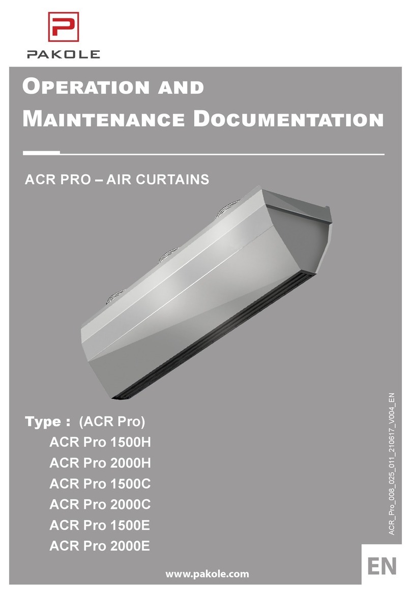
Pakole ACR 1000W Installation guide

EN
www.pakole.com
ACR_008_039_011_221021_V004_en
ACR 1000W ACR 1000E ACR 1000C
ACR 1500W ACR 1500E ACR 1500C
ACR 2000W ACR 2000E ACR 2000C
AIR CURTAINS

ACR air curtains Contents
Contents
1. GENERAL AND SAFETY PRINCIPLES ����������������������������������������������������������3
2. PURPOSE OF THE DEVICE ����������������������������������������������������������������������������3
3. BASIC TECHNICAL PARAMETERS ���������������������������������������������������������������4
4. HEAT OUTPUT RANGES���������������������������������������������������������������������������������4
5. ����������������������������������������������������������������������������������������������������6
6. CONTROL PANEL ��������������������������������������������������������������������������������������������������������������10
7. ACR DOOR SWITCH����������������������������������������������������������������������������������������������������������10
8. DIAGRAMS OF ELECTRICAL CONNECTIONS���������������������������������������������������������������� 11
9. DIMENSIONS OF THE ACR 1000-1500-2000 W, E, C CURTAINS���������������16
10. OPERATION AND MAINTENANCE���������������������������������������������������������������17
11. TROUBLESHOOTING AND TECHNICAL PROBLEMS��������������������������������17

3
ACR air curtains Operation and Maintenance Documentation
1. GENERAL AND SAFETY PRINCIPLES
The ACR air curtains are manufactured in compliance with the rules and standards concerning quality, ecology, utility and work
comfort . Before starting the device be sure to read the Manual carefully.
The ACR air curtains are delivered ready-to-use in a cardboard package that is to protect from any mechanical damages. The
package consists of: the device, the Manual (Operation and Maintenance Documentation) and the Guarantee. If the optional
automatic control ordered, it shall be delivered in a separate package. Make sure all the aforementioned elements are in the
package immediately after the delivery. In the absence of any element, please ll in the suitable carrier document.
• Do not use the curtain in rooms containing any ammable and/or combustible substances, biological substances or in environments
with corrosive air components.
• Do not use the curtain in rooms with relative humidity above 80%
• Do not leave the curtain ON unattended for long periods
• Do not use the curtain without proper grounding
• Do not turn the curtain on without protective cover in place
• Before conducting any maintenance or cleaning work or during the break in operation for an extended period of time, make sure you
unplug the power cable
• To connect the air curtain, use a supply cable with a fork that protects against unintended disconnecting from the power
• When the air curtain is connected directly to the cable, please make sure there is a splitter protecting against any undesired discon-
necting
• Pay special attention while transporting the device not to damage the casing
• When the device is being operated, ensure the safety rules in accordance with the labor standards relating to the operation of any
electrical devices
• Do not place any objects on the curtain or reduce the airow in order to ensure the re safety and if sparks or a damaged supply
cable noticed, discontinue the operation immediately
• Electricity network, to which the curtain is connected, should be protected against overloading and short circuit
• To avoid serious danger of electric shock, installation must be performed by a qualied electrician
• To avoid the serious danger to electric shock disconnect the power supply prior to conducting any repair or maintenance work
• Any leakage repairs of the heating medium in the device, of which pipes are under pressure, is strictly prohibited
• Cut-o/stop valve must be used to supply a heating medium
• It is prohibited to connect grounding-type plug to water pipe, gas tubes, lightning conductors, telephone or antenna network
• Wait for at least 3 hours before connecting the device from the power supply if the temperature while transporting is below zero
NOTICE!
CAUTION!
2. PURPOSE OF THE DEVICE
The air curtain is intended to be used in regions with a moderate and cold climate, in spaces where temperature ranges from -10 to
+40°C, in conditions free from external factors such as pollens and hydrometeor (horizontal precipitation).
In winter, air curtains protect against heat loss in rooms by directing an airstream across the entrance way and preventing cold air
from entering the heated space.. In summer, the curtains may be used as cooling devices preventing the entry of hot air and
pollutants from outside.
The ACR air curtains are designed to protect against heat losses in buildings of medium and high capacity and with a required
mounting height is of 4 m such as:
• supermarkets, large retail space,
• car showrooms and service stations,
• sports and show halls,
• exhibition surfaces

ACR air curtains Contents
3. BASIC TECHNICAL PARAMETERS
4. HEAT OUTPUT RANGES
ACR 1000-1500-2000 W Air curtains with water heater
* Heat output for water agent 90/70 and inlet air temperature 0°C.
** Temperature increase for 18°C ambient air.
*** Power consumption for ambient air temperature 18°C and cable length 10m.
Energy consumption [A] goes higher in relation to decrease of air inlet temperature or extension of supply cables length.
Noise level measured in distance of 3 m in open space building.
Parameters Curtain with water heater Curtain with electric heater
ACR 1000W ACR 1500W ACR 2000W ACR 1000E ACR 1500E ACR 2000E
Length of unit m 1 1.5 2 1 1.5 2
Max� installation height m 4 4 4 4 4 4
Max� air output m3/h 1200 / 1550 / 2000 2200 / 3000 / 3600 2900 / 4000 / 4800 1200 / 1550 / 2000 2200 / 3000 / 3600 2900 / 4000 / 4800
Heat output * kW 10–16 20–29 25–40 4–7 6.5–11 8.5–14
Temperature increase** Δt - - - 12 13 14
Max� working pressure MPa 1.6 1.6 1.6 - - -
Connection nozzles Ø Inch 1/2” 1/2” 1/2” - - -
Motor power consumption V/Hz A 230/50 1.4A 230/50 1.8A 230/50 2.4A 230/50 1.4A 230/50 1.8A 230/50 2.4A
Motor power W37 / 80 / 160 51 / 106 / 220 75 / 162 / 320 37 / 80 / 160 51 / 106 / 220 75 / 162 / 320
Electric heater consumption*** V/Hz A - - - 400/50 12.6A 400/50 19.1A 400/50 25.1A
Weight with water / without water kg 18.0 / 16.5 22.6 / 20.5 31.0 / 28.0 17 21.5 29
Sound level dB (A) 44 / 49 / 59 45 / 49 / 61 46 / 49 / 61 44 / 49 / 59 45 / 49 / 61 46 / 49 / 61
Protection Class IP IP21 IP21 IP21 IP21 IP21 IP21
Parameters Curtain without heater
ACR 1000C ACR 1500C ACR 2000C
Length of unit m 1 1.5 2
Max� installation height m 4 4 4
Max� air output m3/h 1250 / 1600 / 2100 2250 / 3100 / 3700 3000 / 4200 / 5000
Heat output * kW - - -
Temperature increase** Δt - - -
Max� working pressure MPa - - -
Connection nozzles Ø Inch - - -
Motor power consumption V/Hz A 230/50 1.4A 230/50 1.8A 230/50 2.4A
Motor power W37 / 80 / 160 51 / 106 / 220 75 / 162 / 320
Electric heater consumption*** V/Hz A - - -
Weight with water / without water kg 15 18.5 25
Sound level dB (A) 45 / 50 / 60 46 / 50 / 61 47 / 50 / 61
Protection Class IP IP21 IP21 IP21
ACR 1000W
Inlet/outlet water temperature 50/30 60/40 70/50 80/60 90/70
Inlet air temperature 0 5 10 15 20 0 5 10 15 20 0 5 10 15 20 0 5 10 15 20 0 5 10 15 20
III. max. air flow – 2000 m3/h
Heat output [kW] 6,6 5,6 4,6 3,6 2,6 9,0 7,9 6,9 5,8 4,8 11,3 10,3 9,2 8,1 7,1 13,7 12,6 11,5 10,5 9,4 16,0 14,9 13,9 12,8 11,7
Outlet air temperature [°C] 11,4 14,9 18,3 21,9 25,4 14,9 18,3 21,8 25,2 28,7 18,4 21,8 25,2 28,7 32,1 21,9 25,3 28,7 32,1 35,5 25,4 28,8 32,2 35,6 39,0
Water flow [m3/h] 0,2 0,2 0,2 0,1 0,1 0,4 0,3 0,3 0,2 0,2 0,5 0,4 0,4 0,3 0,3 0,6 0,5 0,5 0,4 0,4 0,7 0,6 0,6 0,5 0,5
Pressure drop [kPa] 1,0 1,0 0,6 0,6 0,3 2,0 2,0 1,0 1,0 1,0 4,0 3,0 2,0 2,0 1,0 5,0 5,0 4,0 3,0 2,0 7,0 6,0 5,0 5,0 4,0
II. max. air flow – 1550 m3/h
Heat output [kW] 5,9 5,0 4,2 3,3 2,4 7,9 7,0 6,1 5,3 4,4 10,0 9,1 8,2 7,2 6,3 12,0 11,1 10,2 9,2 8,3 14,0 13,1 12,2 11,2 10,3
Outlet air temperature [°C] 12,5 15,8 19,1 22,4 25,8 16,4 19,6 22,9 26,2 29,5 20,3 23,5 26,8 30,0 33,3 24,2 27,4 30,6 33,9 37,1 28,0 31,3 34,5 37,7 40,9
Water flow [m3/h] 0,2 0,2 0,1 0,1 0,1 0,3 0,3 0,2 0,2 0,2 0,4 0,4 0,3 0,3 0,2 0,5 0,4 0,4 0,4 0,3 0,6 0,5 0,5 0,5 0,4
Pressure drop [kPa] 1,0 1,0 0,5 0,5 0,2 2,0 2,0 1,0 1,0 1,0 3,0 2,0 2,0 1,0 1,0 4,0 3,0 3,0 2,0 2,0 6,0 5,0 4,0 4,0 3,0
I. max. air flow – 1200 m3/h
Heat output [kW] 5,3 4,5 3,8 3,0 2,3 7,0 6,3 5,5 4,7 3,9 8,8 8,0 7,2 6,4 5,6 10,5 9,7 8,9 8,1 7,3 12,2 11,4 10,6 9,8 9,0
Outlet air temperature [°C] 13,7 16,8 19,9 23,0 26,2 18,0 21,1 24,4 27,2 30,3 22,3 25,3 28,4 31,5 34,5 26,6 29,6 32,7 35,7 38,8 30,9 33,9 36,9 40,0 43,0
Water flow [m3/h] 0,2 0,2 0,1 0,1 0,1 0,3 0,2 0,2 0,2 0,1 0,3 0,3 0,3 0,2 0,2 0,4 0,4 0,4 0,3 0,3 0,5 0,5 0,4 0,4 0,4
Pressure drop [kPa] 1,0 0,8 0,5 0,5 0,2 1,0 1,0 1,0 0,7 0,6 2,0 2,0 1,0 1,0 1,0 3,0 3,0 2,0 2,0 1,0 4,0 4,0 3,0 3,0 2,0

5
ACR air curtains Operation and Maintenance Documentation
ACR 1000-1500-2000 E Air curtains with electric heater
• Lack of voltage on surface of electric coil
• Signicantly lower coil temperature in comparison to old type of electric heaters (e.g. heat-
ing wires, spirals)
• Large heat exchange surface (surface of contact of the heat exchanger with heated air)
• Fully automatic heat control depending on air ow
• Complete elimination of the risk of system overheating due to self regulating heating mod-
ules (heat capacity automatically reduces when air ow goes down)
• Low energy consumption
ACR E series (with electric heater) are based on a new type of PTC electric coils J It is a modern and safe solution, additional advan-
tages of PTC heaters
ACR 1500W
Inlet/outlet water temperature 50/30 60/40 70/50 80/60 90/70
Inlet air temperature 0 5 10 15 20 0 5 10 15 20 0 5 10 15 20 0 5 10 15 20 0 5 10 15 20
III. max. air flow – 3600 m3/h
Heat output [kW] 13,5 11,7 10,0 8,2 6,4 17,4 15,6 13,8 12,1 10,3 21,3 19,5 17,7 15,9 14,1 25,1 23,3 21,6 19,7 18,0 29,0 27,2 25,4 23,6 21,8
Outlet air temperature [°C] 11,9 15,4 18,9 22,5 26,0 15,1 18,6 22,1 25,7 29,2 18,3 21,8 25,3 28,9 32,4 21,5 25,0 28,6 32,0 35,6 24,7 28,2 31,7 35,2 38,7
Water flow [m3/h] 0,5 0,4 0,3 0,2 0,2 0,6 0,6 0,5 0,4 0,3 0,8 0,7 0,7 0,6 0,5 1,0 0,9 0,8 0,7 0,7 1,2 1,1 1,0 0,9 0,8
Pressure drop [kPa] 4,0 3,0 2,0 1,0 1,0 8,0 6,0 4,0 3,0 2,0 12,0 10,0 8,0 6,0 5,0 17,0 14,0 12,0 10,0 8,0 22,0 19,0 17,0 14,0 12,0
II. max. air flow – 3000 m3/h
Heat output [kW] 12,5 10,9 9,3 7,8 6,1 16,1 14,4 12,8 11,2 9,6 19,6 17,9 16,3 14,7 13,1 23,1 21,4 19,8 18,2 16,6 26,5 24,9 23,3 21,6 20,0
Outlet air temperature [°C] 12,7 16,1 19,5 22,9 26,3 16,2 19,6 23,0 26,4 29,8 19,7 23,1 26,5 29,9 33,2 23,2 26,5 29,9 33,3 36,7 26,6 30,0 33,4 36,7 40,1
Water flow [m3/h] 0,4 0,4 0,3 0,2 0,2 0,6 0,5 0,4 0,4 0,3 0,7 0,7 0,6 0,5 0,5 0,9 0,8 0,8 0,7 0,7 1,1 1,0 0,9 0,8 0,8
Pressure drop [kPa] 4,0 3,0 2,0 1,0 0,6 6,0 5,0 4,0 3,0 2,0 10,0 8,0 6,0 5,0 4,0 14,0 12,0 10,0 8,0 7,0 18,0 16,0 14,0 12,0 10,0
I. max. air flow – 2200 m3/h
Heat output [kW] 11,0 9,7 8,4 7,0 5,7 14,0 12,6 11,3 9,9 8,6 16,9 15,5 14,2 12,9 11,5 19,8 18,4 17,1 15,7 14,4 22,7 21,3 20,0 18,6 17,3
Outlet air temperature [°C] 14,2 17,4 20,6 23,7 26,9 18,2 21,3 24,5 27,7 30,9 22,1 25,3 28,5 31,6 34,8 26,1 29,2 32,4 35,6 38,7 30,0 33,1 36,3 39,5 42,6
Water flow [m3/h] 0,4 0,3 0,2 0,2 0,1 0,5 0,4 0,4 0,3 0,3 0,6 0,6 0,5 0,4 0,4 0,8 0,7 0,6 0,6 0,5 0,9 0,8 0,8 0,7 0,6
Pressure drop [kPa] 3,0 2,0 1,0 1,0 0,6 5,0 4,0 3,0 2,0 1,0 7,0 6,0 5,0 4,0 3,0 10,0 8,0 7,0 6,0 5,0 12,0 11,0 10,0 8,0 7,0
ACR 2000W
Inlet/outlet water temperature 50/30 60/40 70/50 80/60 90/70
Inlet air temperature 0 5 10 15 20 0 5 10 15 20 0 5 10 15 20 0 5 10 15 20 0 5 10 15 20
III. max. air flow – 4800 m3/h
Heat output [kW] 19,5 17,2 14,8 12,4 9,9 24,7 22,3 19,9 17,5 15,1 29,8 27,4 25,0 22,6 20,2 34,9 32,5 30,1 27,7 25,3 40,0 37,6 35,2 32,8 30,4
Outlet air temperature [°C] 12,5 16,0 19,5 23,0 26,5 15,7 19,2 22,7 26,2 29,7 18,9 22,4 25,9 29,4 32,9 22,1 25,6 29,1 32,6 36,1 25,2 28,7 32,2 35,7 39,2
Water flow [m3/h] 0,7 0,6 0,5 0,4 0,2 0,9 0,8 0,7 0,6 0,5 1,1 1,0 0,9 0,8 0,7 1,4 1,2 1,1 1,0 0,9 1,6 1,5 1,4 1,3 1,2
Pressure drop [kPa] 9,0 6,0 4,0 3,0 1,0 15,0 12,0 9,0 7,0 5,0 22,0 19,0 15,0 12,0 9,0 32,0 27,0 23,0 19,0 15,0 42,0 37,0 32,0 27,0 23,0
II. max. air flow – 4000 m3/h
Heat output [kW] 18,2 16,0 13,8 11,7 9,4 22,8 20,7 18,5 16,3 14,1 27,5 25,3 23,1 20,9 18,8 32,1 29,9 27,7 25,5 23,4 36,6 34,5 32,3 30,1 27,9
Outlet air temperature [°C] 13,3 16,7 20,1 23,5 26,8 16,8 20,2 23,6 27,0 30,3 20,3 23,7 27,0 30,4 33,8 23,7 27,1 30,5 33,8 37,2 27,1 30,5 33,9 37,3 40,6
Water flow [m3/h] 0,6 0,5 0,4 0,3 0,2 0,8 0,7 0,6 0,5 0,4 1,0 0,9 0,8 0,7 0,6 1,2 1,1 1,0 0,9 0,8 1,4 1,3 1,2 1,1 1,0
Pressure drop [kPa] 7,0 5,0 4,0 2,0 1,0 12,0 10,0 7,0 5,0 4,0 19,0 16,0 13,0 10,0 8,0 26,0 22,0 19,0 16,0 13,0 35,0 30,0 26,0 22,0 19,0
I. max. air flow – 2900 m3/h
Heat output [kW] 15,9 14,1 12,3 10,5 8,7 18,8 18,0 16,2 14,4 12,6 23,6 21,8 20,0 18,2 16,4 27,4 25,6 23,8 22,0 20,2 31,2 29,4 27,6 25,8 24,0
Outlet air temperature [°C] 15,0 18,1 21,3 24,4 27,5 18,9 22,1 25,2 28,4 31,5 22,9 26,0 29,2 32,3 35,5 26,8 29,9 33,1 36,2 39,4 30,7 33,8 37,0 40,1 43,3
Water flow [m3/h] 0,5 0,4 0,4 0,3 0,2 0,7 0,6 0,5 0,4 0,4 0,8 0,8 0,7 0,6 0,5 1,0 0,9 0,9 0,8 0,7 1,2 1,1 1,0 1,0 0,9
Pressure drop [kPa] 5,0 4,0 3,0 2,0 1,0 9,0 7,0 5,0 4,0 3,0 13,0 11,0 9,0 7,0 5,0 18,0 16,0 13,0 11,0 9,0 24,0 21,0 18,0 16,0 13,0
ACR 1000E ACR 1500E ACR 2000E
Inlet air temperature [°C] 0 5 10 15 20 0 5 10 15 20 0 5 10 15 20
Heat output [kW] 7,0 7,0 7,0 7,0 7,0 11,0 11,0 11,0 11,0 11,0 14,0 14,0 14,0 14,0 14,0
Outlet air temperature [°C] 12 18 22 27 32 13 18 23 28 33 14 19 24 29 34
6
ACR air curtains Operation and Maintenance Documentation
5. INSTALLATION
When deciding on the air curtain position you should take into account such factors as:
• Ease of access for servicing,
• Access to water and electricity supplies
It is recommended to install the air curtain in position above the entrance opening, on the wall or under the ceiling, on support pins
or horizontal mounting brackets. It is also possible to mount it vertically to a wall or other structure using vertical mounting brackets.
It’s important to make sure that the unit is properly levelled. In case of positioning in a dierent way than horizontal or vertical, during
installation, damage to the fan may occur and in consequence malfunction of the unit.
Inlets and outlets cannot be blocked by any objects. When installing the curtains, keep in mind that you will have free access to the
control panel. With larger door openings, it is possible to mount more curtains of the same type, one by one, to create an
uninterrupted air ow. The curtain is permanently mounted in either a horizontal or vertical position (on the left/right side of the
entrance).
Curtain connection should be done in a serviceable manner, manual shut-o valves should be installed on both nozzles to enable
disconnection. In case of a solenoid valve (option - automatics), it must be connected at the water outlet of the device, otherwise it
may be damaged. When tightening the pipeline to the exchanger, the heater connection must be protected against torque (which
may cause leakage in the exchanger).
Horizontal installation under the ceiling using mounting pins
Installation under the ceiling is done by using 4 M8 pins. In order to hang the device on the pins, drill holes Ø 8-9mm in the EPP
housing directly in front of the existing holes in the steel inlet grille. The exact location is indicated by special tags on the EPP
housing. The pins should be screwed into the nippers at a depth of 10-14mm.

7
ACR air curtains Operation and Maintenance Documentation
It is important to note that the minimum distance between the device and the ceiling is not less than 150 mm� This will
Wall installation by means of a horizontal brackets
The curtain can be mounted to the wall in a horizontal position using 2 mounting
brackets to the horizontal system. In the brackets there are Ø9mm holes for M8
screws. In the EPP housing, drill holes Ø 12-13mm in front of existing holes in the
steel intake grille. The exact location is indicated by the special tags on the EPP
housing and the gure below. Then insert the spacer sleeves into the holes and x
the brackets. Screw the remaining screws into the nuts under the steel intake grille
so that both grips are in one plane. Locknuts under the handles are used to secure
the screws from unscrewing.

8
ACR air curtains Operation and Maintenance Documentation
It is also possible to install the unit vertically with the engine downwards and upwards. Two vertical mounts are used for this purpose. In
the brackets there are Ø9mm holes for M8 screws. In the EPP housing, drill holes Ø 12-13mm in front of existing holes in the steel in-
take grille. The exact location is indicated by special tags on the EPP housing and the gure below. Then insert the spacer sleeves into
the holes and x the brackets. Screw the remaining screws into the nuts under the steel intake grille so that both grips are in one plane.
Locknuts under the handles are used to secure the screws from unscrewing.
Installation using brackets for vertical mounting

9
ACR air curtains Operation and Maintenance Documentation
It is important to note that the minimum distance between the unit and the oor for installation with engine at the bottom is not less than
100mm. This allows access to the electrical terminal strip and to the water exchanger vent.
The connection of the heating medium to the heat curtain, using G 1/2” threaded connections, should be made on the basis of a design
by an authorized designer. If the air curtain is connected to a district heating network without a mixing unit, a water lter is required.
In case of horizontal and vertical mounting with nozzles at the top, the exchanger is vented through the nozzles. If the device is mount-
ed vertically with nozzles at the bottom, to vent the exchanger, use a vent which is located on the exchanger collector on the engine
side.
To connect the power supply, control and / or bleed the Exchange move out the right lid, which is fastened with the lock to the lower
steel housing and the main housing EPP. The lid is disassembled in the direction shown by the arrows in the gure below. The lid
should be grasped in the following places indicated in the drawing and should be gradually “released” from the locks for several milli-
metres. Cable entries for power and control cables are located on the inlet grille.
Connection of heating medium
Connecting the power supply and control system of the curtain

10
ACR air curtains Operation and Maintenance Documentation
6. CONTROL PANEL
The curtain control is done by using the COMFORT control panel, which allows to adjust the ow and air temperature. The control
panel should be located outside the curtain airow zone. Up to 2 ACR curtains can be connected to one COMFORT panel.
Description of the COMFORT control panel switches
ON/OFF – switching on/o of the machine
I-II-III – fan gear switches, COMFORT terminal strip clamps
clamp 8 - high speed III
clamp 7 - middle speed II
clamp 6 - low speed I
HEAT - when the room temperature is lower than the set value, the thermostat switches on the
fan (ACR W, E, C), the electric heater (ACR E) and the valve actuator (ACR W); When the set
temperature is reached, the fan is switched o, the valve closes the water ow or the electric
heater switches o
FAN / COOL – not supported function, in this settings the device does not work
To install the control panel, unscrew the screw, remove the front cover and panel board, x the panel to the wall, and replace the panel
and cover (installation instructions and xing kit are included in the package).
7. ACR DOOR SWITCH
The ACR (DC) door switch is an additional element for switching the curtain on/o, depending on the opening of the door. It is designed
for indoor installation. It includes:
• Relay cabinet - reed relay switchboard
• Reed relay - Reinforcement for door-tting, hermetic magnetic switch, consisting of a movable and xed element
Scheme of the relay cabinet – reed relay interface
Parameters of relay reed switchboard
• Power supply 230V/50Hz
• Inductive load relay contact 5(A)
• NC magnetic sensor circuit NC
• IP66
Dimensions of reed relay
When installing the ACR door switch, remove the factory-made jumper:
NC-1 for curtain ACR W (curtain with a water heater) / ACR C (curtain without a water heater)
NC-COM for curtain ACR E (curtain with an electric heater)

11
ACR air curtains Operation and Maintenance Documentation
8. DIAGRAMS OF ELECTRICAL CONNECTIONS
The electrical network to which the curtain will be connected should provide protection against overheating and short circuiting. It is
necessary to protect the air curtain by grounding. Electrical installation and connection to the air curtain must be in accordance with
applicable building codes and regulations, electrical connection should be carried out by a qualied person familiar with the above in-
struction. The fan motor has standard internal thermal protection to protect the motor from overheating.
The set does not include: power cord, or main switch.
Diagram of connecting one ACR 1000-1500-2000 W (water heater) and C
(without heater) to the COMFORT panel
• Power supply 230V / 50Hz; Security system B4; Cross section of power supply cables min. 3 x 1mm
• Control Panel COMFORT - 3-speed fan control with thermostat, (OMY 5x 1.0mm)
• Actuator valve - control 230V/50Hz (OMY 2 x 0.75mm - TS Lite),
Diagram of connecting two ACR 1000-1500-2000 W (water heater) and C
(without heater) to one COMFORT panel
• In the MASTER curtain between the L-NC terminals, replace the factory-made fuse (C 3.15) with C 6.3.
• Power supply 230V/50Hz; protection of the C10 system; cross section of power supply cables min. 3 x 1.5 mm
• COMFORT control panel - 3-speed fan control with thermostat (OMY 5x 1.0mm)
• Actuator valve - control 230V / 50Hz (OMY 2 x 0.75mm - TS Lite),

12
ACR air curtains Operation and Maintenance Documentation
Diagram of connection of one ACR 1000-1500-2000 E curtain (electric heater)
to the COMFORT panel
• 400V/50Hz power supply; wire cross section; current protection circuit
• min. 5 x 2,5 mm˛ for G100E ; (B16)
• min. 5 x 2,5 mm˛ for G150E; (B20)
• min. 5 x 4 mm˛ for G200E; (B25)
• Control Panel COMFORT - 3-speed fan control with thermostat, (OMY 5x 1.0mm˛)
• In the MASTER curtain between the L1-NC terminal, replace the factory-made fuse (C 3.15) with C 6.3 400V / 50Hz
power supply; wire cross section; current protection of the system - should be selected according to the parameters
of the individual versions of the curtains
• COMFORT control panel - 3-speed fan control with thermostat (OMY 5x 1.0mm˛)
Diagram of connection of two ACR 1000-1500-2000 E curtain (electric heater)
to one COMFORT panel

13
ACR air curtains Operation and Maintenance Documentation
Diagram of connection of one ACR 1000-1500-2000 E curtain (electric heater)
to the COMFORT panel
In the summer time, it is possible to switch o the electric heater and use the ACR E curtain as a cold curtain (i.e., fan only, electric
heater does not work). In this case, a simple power cut-o installation (shown in the dashed diagram below) must be made.
The installation consist in inserting any on/o switch (labelled as “G”) into the control circuit between terminal 3 on Comfort Panel and
Terminal 2 in the ACR curtain. The on/o switch itself should be installed in a place suitable for the curtain user.
Warning! The Comfort Panel thermostat must be set to max. The on/o switch and the wires to the switch are not included in the
scope of delivery
Connection of ACR curtains based on BMS communication module
• The BMS module for ACR curtains allows to monitoring the operation of the curtain (EMERGENCY/FAILURE signal) and switches
the curtain on/o from the master BMS system.
• With the use of digital signals 0/1 (potential free contact), the BMS can work with any BMS master protocol without need to convert
the signal

14
ACR air curtains Operation and Maintenance Documentation
Connection diagram of ACR 1000-1500-2000 W and C with BMS module
SIGNALS FROM BMS
PZ „READY FOR OPERATION”
• Digital signal “1” from the master BMS (potential-free contact) - Curtain ready for operation
• Digital signal “0” from the master BMS system (potential-free contact open) - Curtain disabled
SIGNALS TO BMS - MONITORING THE CURTAIN WORK (NOTE - ON/OFF switch on the COMFORT panel in ON position,
“READY FOR OPERATION” signal activated):
PP „OPERATION”
• Digital signal “1” (potential-free contact closed) - information about the operation of the curtain- reed relay on - door opened
• Digital signal “0” (potential-free contact opened) – Reed relay o - door closed
• If the contactor is not used - after the “OPERATION” signal is applied, the curtain operates continuously in the thermostat
• mode - digital signal “1” (potential-free contact closed)
• When the curtain is switched o via the thermostat - digital signal “0” (potential-free contact open)
PA „FAILURE”
• With proper operation of the curtain - digital signal “0” (potential-free contact opened)
• After triggering the fuse C3,15 - digital signal “1” - curtain failure (potential-free contact closed)

15
ACR air curtains Operation and Maintenance Documentation
Diagram of connection of ACR 1000-1500-2000 E curtain with BMS module
-
SIGNALS FROM BMS
PZ „READY FOR OPERATION”
• Digital signal “1” from the master BMS (potential-free contact closed) - Curtain ready for operation
• Digital signal “0” from the master BMS system (potential-free contact opened) - Curtain disabled
SIGNALS TO BMS - MONITORING THE CURTAIN WORK (NOTE - ON/OFF switch on the COMFORT panel in ON position,
“READY FOR OPERATION” 1 signal activated):
PP „OPERATION”
• Digital signal “1” (potential-free contact closed) - information about the operation of the curtain- reed relay on - door opened
• Digital signal “0” (potential-free contact opened) - Reed relay o - door closed
• If the contact is not used - after the “WORKING” signal is applied, the curtain operates continuously in the thermostat
• mode - digital signal “1” (potential-free contact closed)
• When the curtain is switched o via the thermostat “0” digital signal (potential-free contact opened)
PA „FAILURE”
• With proper operation of the curtain - digital signal “0” (potential-free contact opened)
• After triggering the fuse C3,15 - digital signal “1” - curtain failure (potential-free contact closed)

16
ACR air curtains Operation and Maintenance Documentation
9. DIMENSIONS OF THE ACR 1000-1500-2000 W, E, C CURTAINS

17
ACR air curtains Operation and Maintenance Documentation
10. OPERATION AND MAINTENANCE
The engine and fan of the ACR air curtains are maintenance-free devices but regular check-ups are advised, especially motor and
bearing (fan’s rotor should rotate freely, free from any axial and radial throws/run-outs and undesired knocks/rattles.
The heat exchanger requires systematic cleaning of all dirts /impurities o. Before the start of the heating period, the heat exchanger is
advised to be cleaned with compressed air directed to the air outlets; there is no need for dismantling of the device.
Pay special attention when cleaning the exchanger’s n due to high possibility of damaging them. If the n is bent use a special tool. If
the device has not been used for a longer period of time, unplug it before the next use.
The heat exchanger is not equipped with any re protection device. The heat exchanger may be damaged if the room temperature
goes below 0°C; anti-freeze liquid must be added to the water circulation/system. Anti-freeze liquid must be appropriate for the material
the exchanger is made of (copper) as well as other elements of the hydraulic system/circulation. The liquid must be diluted with water
accordingly to the manufacturer’s recommendation.
11. TROUBLESHOOTING AND TECHNICAL PROBLEMS
Possible problems and solutions are shown below. To eliminate a problem encountered contact the authorized service.
Fault, symptoms Potential causes Solutions
No heating, fan not operating
No power supply
Check the power switch Check the
power supply Check the power cable – if it is dam-
aged - replace the cable
Damage to the fan Replace the motor
Damage to the switches on control panel Check the switches – if are damaged – replace
Heating medium leakage
• leakage on joints with hot water supply system
• leakage in collector
Loss of tightness Sealing supply system; repairing the heat exchanger
Heat output drop
Temperature of the heating medium diers
from the required one Contaminated heat
exchanger’s surface
Restore the temperature of the heating medium
Clean the surface of the heat exchanger

18
ACR air curtains Operation and Maintenance Documentation
PRESERVE THIS WARRANTY
Type:
Serial no.:
Date of purchasing:
LIMITED GUARANTEE *
The manufacturer guarantee the costumer that the product and its parts are free from materi-
al and production failures. During normal use the warranty is 2 years. This warranty concerns
the first retail customer.
The guarantee concerns the costs of laboratory investigations and the parts, which are need-
ed for proper operation. The delivery and unforeseeable costs belong also to the mending
costs and do not contain compensation costs.
Guarantee mending can only be realized by authorized retailer or service centre.
The guarantee does not concerns the following failures, which are caused by: improper using,
damaging, neglect, accident, lack of maintenance, normal attrition, transformation, modifica-
tion and operation influenceable factor,contaminated fuel, installation of non-suitable part and
mending which is done by not authorized retailer or service station.
The regular maintenance is the owner’s responsibility.
The manufacturer does not assume the responsibility in case of accidentally happened or
directly caused mistake respectively improper using.
*We reserve the right to change of this specification without extra notification� The
guarantee can be applied in accordance with above defined�
Additional guarantee is not accepted�
Guarantee servicing
If your appliance needs guarantee service in that case it can be requested at nearest author-
ized service station giving in the appliance for repairs.
Mending services
Take the appliance to the nearest authorized service station. If the device is not under guar-
antee the service cost will be invoiced to the costumer at defined price. The service centres
are independent from one another and may have different owners. We reserve the right to
change of this specification without extra notification. If you would like to contact us the type
and serial number of device always be at hand. In case of other needed information write to
the distributor.


H-8000 Székesfehérvár, Börgöndi út 8-10.
www.pakole.com
Tel.: +36 22 316 484
www.pakole.com
This manual suits for next models
8
Table of contents
Other Pakole Heater manuals

Pakole
Pakole LH-30 User manual

Pakole
Pakole ACR 100W Installation guide

Pakole
Pakole GTV-E-20A User manual

Pakole
Pakole AIRFUSOR AFR-0 User manual

Pakole
Pakole GTV-E-20A User manual

Pakole
Pakole ZENIT 80+ Series User guide

Pakole
Pakole ZENIT-12 Series User manual

Pakole
Pakole ACR PRO Installation guide

Pakole
Pakole GHI-11 User manual
Popular Heater manuals by other brands

Kampmann
Kampmann Katherm QK Assembly and installation instructions

Nortek
Nortek C8QA Series installation instructions

Toshiba
Toshiba RBC-VNMC-HE1 installation instructions

Remington
Remington HH- 45-KFA User's manual & operating instructions

DeLonghi
DeLonghi DCH5091ER instructions

DeLonghi
DeLonghi HVF3031 Gebruiksaanwijzing